Table of Contents
Advertisement
Advertisement
Table of Contents
Troubleshooting

Related Manuals for horiba APMA-370


Summary of Contents for horiba APMA-370
- Page 1 Ambient CO monitor APMA-370 Operation Manual [eng] CODE:GZ0000051249J...
- Page 2 HORIBA, Ltd. warrants that the Product shall be free from defects in material and workman- ship and agrees to repair or replace free of charge, at option of HORIBA, Ltd., any malfunc- tioned or damaged Product attributable to responsibility of HORIBA, Ltd. for a period of one (1) year from the delivery unless otherwise agreed with a written agreement.
- Page 3 Regulations EU and UK regulations Conformable standards This equipment conforms to the following standards: EMC: EN 61326-1 Class B, Industrial electromagnetic environment Safety: EN 61010-1 RoHS: EN IEC 63000 9. Monitoring and control instruments including industrial monitoring and control instruments EMC: BS EN 61326-1 Class B, Industrial electromagnetic environment...
- Page 4 FCC rules Any changes or modifications not expressly approved by the party responsible for compliance shall void the user's authority to operate the equipment. Warning This equipment has been tested and found to comply with the limits for a Class A digital device, pursuant to part 15 of the FCC Rules.
- Page 5 For Your Safety Hazard classification and warning symbols Warning messages are described in the following manner. Read the messages and follow the instructions carefully. Hazard classification This indicates an imminently hazardous situation which, if not avoided, will result in death or serious injury. This is to be limited to the most extreme situations.
- Page 6 Safety precautions This section provides precautions for using the product safely and correctly and to prevent injury and damage. The terms of DANGER, WARNING, and CAUTION indicate the degree of imminency and hazardous situation. Read the precautions carefully as it contains important safety messages.
- Page 7 This indicates reference information. Documents related to this product The following documents are related to this product. Ambient CO Monitor APMA-370 Instruction Manual (this manual) This volume mainly discusses the operations for daily measurement and daily maintenance work of ambient CO monitor.
-
Page 9: Table Of Contents
Contents OVERVIEW ........Introduction . - Page 10 FUNCTIONALITIES ....... . Data Menu ......... . History Menu .
- Page 11 Troubleshooting ........EXTERNAL INPUT/OUTPUT ......Terminal Block Specifications .
-
Page 13: Overview
Addition of an RS-232C port (optional) will allow you to carry out data communication. System Configuration APMA-370 is a standalone system that allows you to operate it by merely supplying calibration gas. The system can be upgraded by connecting a computer, monitor, recorder, multi-gas calibrator. -
Page 14: Part Names
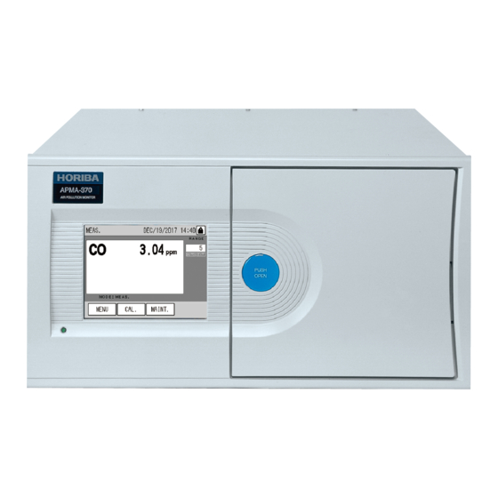
When the front panel door is open Fig. 2 Front panel Name Description When APMA-370 is ON, this LED is illuminated as follows: 1 Power ON LED Green: During normal operation Red: In alarm conditions 2 Touch panel Displays the measured values, alarms, etc. and touch-keys for operation. -
Page 15: Rear Panel
7 Signal connection terminal block For the signals, see “9 EXTERNAL INPUT/OUTPUT” (page 86). Use the supplied power cable. 8 AC Inlet To completely shut off the APMA-370, disconnect the power cable from the AC inlet. 9 TCP/IP connector (optional) Note The measured gas is released from the exhaust outlet at a rate of 1.5 L/min. -
Page 16: Basic Operations
In order to obtain stable, accurate data, perform calibration at the measurement start and regular intervals (see “4 CALIBRATION” (page 11)). If the data logging capability (optional) for the CF is enabled, data logging is automatically executed when the APMA-370 is started again due to the power failure, etc. -
Page 17: Shutdown
2. Ensure that the data logging capability is disabled during data logging (optional). (See the Instruction Manual for APXX-370 Series Compact Flash Memory.) 3. Turn OFF the power of APMA-370. Before a long-term shutdown, it is recommended to replace the filter element (see “7.3... -
Page 18: Basic Operation Flow
2 BASIC OPERATIONS Basic Operation Flow To perform operations, ensure that the installation, wiring, and piping connections have been completed. (Connect the external input/output as necessary.) For the first use Power ON Turn ON the power. “2.1 Start-up (Measurement Start)” (page 4) ↓... -
Page 19: Meas. Screen (Basic Screen)
MEAS. SCREEN (BASIC SCREEN) Note APMA-370 uses a touch screen. Directly press keys displayed on that screen with your finger. When pressing these keys, do not use a ballpoint pen or any other tool with a hard or sharp end. This might cause a malfunction. - Page 20 3 MEAS. SCREEN (BASIC SCREEN) AIC mode: This icon blinks when the AIC sequence is in progress. Fig. 8 AIC mode icon Saving: This icon is illuminated when data is being written to the flash memory or when the data logging capability (optional) is in use. Data is saved when any setting is modified or every 10 minutes during data acquisition.
- Page 21 3 MEAS. SCREEN (BASIC SCREEN) 4: Range display The current range and range mode are displayed. Momentary value range AUTO Fig. 11 Range display Momentary value range: The current momentary value range is displayed. If the displayed unit is different from the factory setting, the range is changed to “RX.”...
- Page 22 3 MEAS. SCREEN (BASIC SCREEN) 6: Active measurement line display The currently selected measurement line is displayed. Active measurement line Fig. 13 Active measurement line display EXT: Displayed when the external input for line switching is used. Active measurement line: The currently selected measurement line is displayed. ZERO: The zero gas line is now being selected.
-
Page 23: Calibration
4 CALIBRATION CALIBRATION In order to acquire stable, accurate data, perform calibration when starting measurement and at regular intervals. There are two types of calibration, the auto calibration (AIC) and the manual calibration. Auto calibration (AIC) The AIC sequence is executed at the specified time intervals or with the externally inputted command to perform the zero calibration and span calibration automatically. -
Page 24: Mode Screen
4 CALIBRATION 2: Span gas concentration value The entered span gas concentration value is displayed. Different values can be entered for the measured gas and span gas lines. Press the displayed span gas concentration value, the SPAN CONC. screen will be displayed (see “4.1.3 Screens for value setting”... -
Page 25: Screens For Value Setting
4 CALIBRATION Press the button for the item to be set. MEAS.: To use the MEAS. line, select this button. SPAN: To use the SPAN line, select this button. ZERO: To use the ZERO line, select this button. EXTERNAL: To use the external contact (optional) for line switching, select this button. The keys allow you to perform the following operations. -
Page 26: Preparation For Calibration
4 CALIBRATION Preparation for Calibration 4.2.1 Entering the span gas concentration value Enter the span gas concentration value to be used for the calibration. 1. Press the displayed MODE setting on the CAL. screen. The MODE screen will be displayed. Fig. - Page 27 4 CALIBRATION Enter a value via the numeric keypad. The keys allow you to perform the following operations. [CANCEL]: Returns to the CAL. screen without changing the settings. [CLEAR]: Deletes the value entered in the edit area. [BACK]: Deletes the just entered figure (1-digit). [SET]: Returns to the CAL.
-
Page 28: Automatic Calibration (Aic)
4 CALIBRATION Automatic Calibration (AIC) Automatic calibration (AIC) is started and performed with the internal clock, according to the AIC sequence and conditions set in advance. The AIC sequence can also be started arbitrarily by pressing the [AIC] key on the CAL screen. 4.3.1 AIC setting 1. - Page 29 4 CALIBRATION Note Only when AIC MODE is set to INTERNAL, the items of START TIME, LIMIT (START-END), and INTERVAL are displayed. These items are not displayed when AIC MODE is set to NONE or EXTERNAL. 4. Press the displayed item to be set. The corresponding setting screen will be displayed.
- Page 30 4 CALIBRATION AIC MODE Specify the method of starting the AIC. Pressing the displayed AIC MODE setting will display the AIC MODE screen. Fig. 21 AIC MODE screen Item Description INTERNAL Selects the mode of using the internal clock to execute AIC at the specified start time and intervals with. Selects the mode of using the external start signal (external contact input) to start AIC.
- Page 31 4 CALIBRATION START TIME Set the time for starting the next AIC sequence. Pressing the displayed START TIME setting will display the START TIME screen. Fig. 22 START TIME screen Item Settable range Year 2000 to 2099 Month 01 to 12 01 to 31 Hour 00 to 23...
- Page 32 4 CALIBRATION LIMIT (START-END) Set the range of time available for starting the AIC sequence. Pressing the displayed LIMIT (START-END) setting will display the LIMIT (START-END) screen. Fig. 23 LIMIT (START-END) screen Item Settable range Start: Hour 00 to 23 Start: Minute 00 to 59 End: Hour 00 to 23...
- Page 33 4 CALIBRATION INTERVAL Set the time interval, which applies if the AIC sequence is started periodically. Pressing the displayed INTERVAL setting will display the INTERVAL screen. Fig. 24 INTERVAL screen Item Settable range 0 to 999 Hour 00 to 23 Minute 00 to 59 Press the value to be changed.
-
Page 34: Precautions In Setting The Aic Sequence
4 CALIBRATION 4.3.2 Precautions in setting the AIC sequence Automatic correction of start time When AIC MODE is set to INTERNAL and an AIC sequence is started, the expected START TIME of the next AIC is calculated using the following equation: Expected START TIME of the next AIC (calculated value) = the current START TIME + INTERVAL If the calculated time is within the settable range of START TIME, the START TIME setting is changed to the calculated time. -
Page 35: Setting The Aic Sequence
4 CALIBRATION 4.3.3 Setting the AIC sequence To set the AIC sequence, go to the AIC SEQUENCE screen. 1. Press the [MENU] key on the MEAS. screen. 2. Press the [] or [] key to display the MENU/SETTING screen. Fig. 27 MENU/SETTING screen 3. - Page 36 4 CALIBRATION CAL. The following CAL. screen for setting will appear. Fig. 30 CAL. screen (for SPAN) 5. Change the setting by entering time on the time setting screen or pressing either [YES] or [NO] button on the CAL. screen, and then press the [SET] key. The setting will be changed and the AIC SEQUENCE screen will be displayed again.
-
Page 37: Starting The Aic Sequence With The [Aic] Key
4 CALIBRATION 4.3.4 Starting the AIC sequence with the [AIC] key 1. Press the [CAL.] key on the MEAS. screen. The CAL. screen will be displayed. Fig. 32 CAL. screen 2. Press the [AIC] key. The AIC start message will appear. Fig. -
Page 38: Manual Calibration
4 CALIBRATION Manual Calibration After preparing for the calibration (see “4.2 Preparation for Calibration” (page 14),) perform the zero calibration and the span calibration in this order. 4.4.1 Operational flow The operational flow for manual calibration is described below: When using the calibration gas line: When using the measured gas line Reference page Gas line connection check... -
Page 39: Zero Calibration
4 CALIBRATION 4.4.2 Zero calibration 1. On the CAL. screen, check that the proper measurement line is selected. If necessary, press the displayed MODE setting on the CAL. screen to display the MODE screen, and then change the setting and press the [SET] key on the MODE screen. -
Page 40: Span Calibration
4 CALIBRATION 4.4.3 Span calibration 1. On the CAL. screen, check that the proper measurement line is selected. If necessary, press the displayed MODE setting on the CAL. screen to display the MODE screen, and then change the setting and press the [SET] key on the MODE screen. -
Page 41: Finishing Calibration
4 CALIBRATION 4.4.4 Finishing calibration 1. When using the calibration gas line, display the MODE screen and change the measurement line to [MEAS.]. When using the measured gas line, supply the sample gas to the measured gas line. 2. Press the [CLOSE] key on the CAL. screen. The MEAS. screen will be displayed again and the measurement will start. -
Page 42: Data Processing
5 DATA PROCESSING DATA PROCESSING Based on the acquired data, average, integration, and rolling average values are calculated. These values can be checked on the screen. To check the data, press the [MENU] key on the MEAS. screen to display the MENU/DATA screen and then press the button of the data to be displayed. - Page 43 5 DATA PROCESSING Screens for data check The common functionalities of the screens for data check are described below: On the MENU/DATA screen, press the button of the data to be displayed. The following screen for data check will be displayed. Alarm icon Fig.
- Page 44 5 DATA PROCESSING Deleting data All the records of the calculated average and integration data can be deleted at a time. As for the rolling average data, the currently calculated one can be deleted. 1. Check that the keys are unlocked (Fig. 10 on page 8). If the keys are locked, unlock them (see “6.8 Key Lock”...
-
Page 45: Average
5 DATA PROCESSING Average An average data is calculated by summing the measured values (momentary values) acquired every 1 second for a specified calculation period, and then dividing the cumulative total by the data counts. There are three AVERAGE data (AVERAGE 1 to AVERAGE 3), calculated using different cal- culation periods. - Page 46 5 DATA PROCESSING Average calculation The timing of average calculation start or end is based on the internal clock. If power shutdown occurs or if the internal clock is put forward: The momentary data during the power shutdown or the put-forwarded time period will be regarded as missing.
-
Page 47: Integration
5 DATA PROCESSING Integration A integration data is calculated by dividing the measured values (momentary values) acquired every 1 second by 3600 and summing these data for a specified calculation period. This calculation result can be checked on the INTEGRATION screen. The calculation period is 1 hour, and the data capacity is 1000 data. - Page 48 5 DATA PROCESSING Integration calculation In the case of the standard specification, the timing of the integration calculation start and end is controlled by sending the ON signal to the integration value reset input (RST input) on the signal connection terminal block (see “6.5.4 Integration reset setting” (page 55)), or by receiving the integration calculation reset command via serial communication (refer to the instruction manual of APXX-370 Series RS-232C).
-
Page 49: Rolling Average
5 DATA PROCESSING Rolling Average The rolling average value between the current time and the 3-hour earlier point is sequentially displayed on the ROLLING AVERAGE screen as time passes. Fig. 46 ROLLING AVERAGE screen For the screen functionalities, see " Screens for data check" (page 31). Rolling average calculation ... -
Page 50: Functionalities
6 FUNCTIONALITIES FUNCTIONALITIES The MEAS. screen allows you to use the following functionalities. By starting with the [MENU] key Displaying average, integration, and rolling average values (see page 30) Displaying history (see page 40) Checking/adjusting analog output (see page 44) ... - Page 51 6 FUNCTIONALITIES MENU screens Pressing the [MENU] key on the MEAS. screen allows you to use functionalities such as data review and settings. Fig. 47 MENU screen (DATA) The following 7 different MENU screens are available DATA (Fig. 39 on page 30) ...
-
Page 52: Data Menu
6 FUNCTIONALITIES Data Menu The DATA menu allows you to display average, integration, and rolling average data. For further information on the MENU/DATA screen, see “5 DATA PROCESSING” (page 30). History Menu The HISTORY menu is used to display the calibration history and alarm history and AIC history (optional). - Page 53 6 FUNCTIONALITIES The keys allow you to perform the following operations. [CLOSE]: Returns to the MENU/HISTORY screen. [DELETE]: Displays the message confirming data deletion (Fig. 50 on page 41). []: Displays the previous page. []: Displays the next page. Note The [DELETE] key is hidden when the keys are locked.
-
Page 54: Calibration History
6 FUNCTIONALITIES 6.2.1 Calibration history Press the [CAL. ADJUSTMENT HISTORY] button on the MENU/HISTORY screen. The latest calibration history will be displayed. Fig. 52 CAL. ADJUSTMENT HISTORY screen For the screen functionalities, see " Operation of the HISTORY screens" (page 40). 6.2.2 Alarm history Press the [ALARM HISTORY] button on the MENU/HISTORY screen. -
Page 55: Aic History (Optional)
6 FUNCTIONALITIES 6.2.3 AIC history (optional) Press the [AIC HISTORY] button on the MENU/HISTORY screen. The latest AIC history will be displayed. Concentration before span calibration Concentration before zero calibration Span gas concentration Data time Alarm icon Fig. 54 AIC HISTORY screen For each measurement component, the concentration value before zero calibration, the concentration value before span calibration, the span gas concentration value, and unit are displayed. -
Page 56: Maintenance Menu
6 FUNCTIONALITIES Maintenance Menu Fig. 55 MENU/MAINTENANCE screen The keys allow you to perform the following operations. [ANALOG OUTPUT]: Displays the ANALOG OUTPUT screen (Fig. 56 on page 44). [ANALOG INPUT]: Displays the ANALOG INPUT screen (Fig. 59 on page 48). [HOUR METER]: Displays the HOUR METER screen (Fig. - Page 57 6 FUNCTIONALITIES The buttons allow you to select and check the output modes (see below). The keys allow you to perform the following operations. [CLOSE]: Returns to the MENU/MAINTENANCE screen. [ZERO]: Displays the DA ADJUST/ZERO screen for zero calibration of analog output (Fig.
- Page 58 6 FUNCTIONALITIES Adjusting the zero output and span output Zero output adjustment 1. Output [0%] on the ANALOG OUTPUT screen and then press the [ZERO] key. The DA ADJUST/ZERO screen will be displayed. Point value Fig. 57 DA ADJUST/ZERO screen The respective output point values of the channels are displayed.
- Page 59 6 FUNCTIONALITIES Span output adjustment 1. Output [100%] on the ANALOG OUTPUT screen and then press the [SPAN] key. The DA ADJUST/SPAN screen will be displayed. Point value Fig. 58 DA ADJUST/SPAN screen The respective output point values of the channels are displayed. The outputs allocated to the channels are as follows: Analog output Terminal...
-
Page 60: Analog Input
Standard value: 1 L/min to 2 L/min Flow rate of calibration gas overflow (optional) OVER FLOW L/min Standard value: 1.2 L/min or more Power supply voltage inside the APMA-370 DC 24V Standard value: 24 V ±0.5 V Power supply voltage inside the APMA-370 DC 5V... -
Page 61: Hour Meter
6 FUNCTIONALITIES 6.3.3 Hour meter Press the [HOUR METER] button on the MENU/MAINTENANCE screen. The HOUR METER screen will be displayed. This screen shows the cumulative operating hours of consumables. If you reset this counts when replacing the corresponding consumables, the displayed count will help you determine the approximate time of the next replacement. -
Page 62: Range Menu
6 FUNCTIONALITIES Range Menu The MENU/RANGE screen is used to change the analog output ranges by changing the full- scale setting. Fig. 62 MENU/RANGE screen The buttons allow you to perform the following operations. [ANALOG OUTPUT1 RANGE]: Displays the ANALOG OUTPUT1 RANGE screen (Fig. 65 on page 52). - Page 63 6 FUNCTIONALITIES The following key allows you to perform the following operations. [CLOSE]: Returns to the MENU/RANGE screen. Automatic range switching operation (for the standard specification) The combinations used for the automatic range switching depends upon the specification. For the standard specification, all of the fixed ranges are used. The analog output range for which the auto range switching is set changes automatically as follows: When the reading exceeds 90% of the current range, the measurement range will be switched to ...
-
Page 64: Analog Output 1 Range (Momentary Value)
6 FUNCTIONALITIES 6.4.1 ANALOG OUTPUT 1 range (momentary value) Press the [ANALOG OUTPUT 1 RANGE] button on the MENU/RANGE screen. The ANALOG OUTPUT1 RANGE screen will be displayed. Fig. 65 ANALOG OUTPUT1 RANGE screen For the screen functionalities, see " ANALOG OUTPUT RANGE screens" (page 50). 6.4.2 ANALOG OUTPUT 2 range (rolling average) Press the [ANALOG OUTPUT 2 RANGE] button on the MENU/RANGE screen. -
Page 65: Setting Menu
6 FUNCTIONALITIES Setting Menu Fig. 67 MENU/SETTING screen The buttons allow you to perform the following operations. [TIME ADJUST]: Displays the TIME ADJUSTMENT screen (Fig. 68 on page 54). [AIC]: Displays the AIC screen (Fig. 20 on page 16). [AIC SEQUENCE]: Displays the AIC SEQUENCE screen (Fig. -
Page 66: Time Adjustment
6 FUNCTIONALITIES 6.5.1 Time adjustment Press the [TIME ADJUST] button on the MENU/SETTING screen. The TIME ADJUST screen will be displayed. This screen allows you to adjust the internal clock. Note Since the adjustment of the internal clock affects the data recording, give precautionary attention (see "... -
Page 67: Integration Reset Setting
6 FUNCTIONALITIES 6.5.4 Integration reset setting Press the [INT. RESET] button on the MENU/SETTING screen. The INT. RESET SETTING screen will be displayed. This screen allows you to select a method for resetting the integration value, specify resetting time, and enable/disable the telemeter alarm. Fig. -
Page 68: Unit Conversion Factor
6 FUNCTIONALITIES 6.5.5 Unit conversion factor Press the [UNIT CONVERSION FACTOR] button on the MENU/SETTING screen. The UNIT CONVERSION FACTOR screen will be displayed. Unit conversion result by using the currently specified unit conversion factor Current concentration Currently specified unit conversion factor Fig. - Page 69 6 FUNCTIONALITIES Changing the unit conversion factor 1. Press the button of the unit conversion factor to be changed. The UNIT CONVERSION FACTOR screen for setting will be displayed. Numeric keypad Edit area Fig. 71 UNIT CONVERSION FACTOR screen for setting The currently select conversion factor is displayed in parentheses below the edit area.
-
Page 70: System Menu
6 FUNCTIONALITIES System Menu Fig. 72 MENU/SYSTEM screen The buttons allow you to perform the following operations. [LCD SETTING]: Displays the LCD SETTING screen (Fig. 73 on page 58). [TOUCH PANEL ADJUSTMENT]: Displays the TOUCH PANEL ADJUSTMENT screen (Fig. 75 on page 60). [PASSWORD SETTING]: Displays the PASSWORD SETTING screen (Fig. - Page 71 6 FUNCTIONALITIES Setting the time for automatic backlight OFF 1. Press the button of the time for automatic backlight OFF. The BACK LIGHT TIME PERIOD screen will be displayed. Fig. 74 BACK LIGHT TIME PERIOD screen The time is set by choosing a button of time setting. The keys allow you to perform the following operations.
-
Page 72: Touch Panel Adjustment
6 FUNCTIONALITIES 6.6.2 Touch panel adjustment Press the [TOUCH PANEL ADJUSTMENT] button on the MENU/SYSTEM screen. The TOUCH PANEL ADJUSTMENT screen will be displayed. If the displayed buttons and keys deviate from their respective touch positions, you can adjust the touch panel by performing the following steps. Note Such deviations on the touch panel can be adjusted within a range of 36 dots. -
Page 73: Password Setting
6 FUNCTIONALITIES 6.6.3 Password setting Note The password is required to change the password. 1. Press the [PASSWORD SETTING] button on the MENU/SYSTEM screen. The PASSWORD SETTING screen will be displayed. Fig. 77 PASSWORD SETTING screen (requiring the current password) Enter a value via the numeric keypad. - Page 74 6 FUNCTIONALITIES Fig. 78 PASSWORD SETTING screen (requiring a new password) Enter a value via the numeric keypad. The function of each key is the same as on the PASSWORD SETTING screen (requiring the current password) (Fig. 77 on page 61). 3.
-
Page 75: Data Saving
Data saving To save data in the memory manually, press the [SAVE] button on the MENU/SYSTEM screen. Before turning OFF the APMA-370, be sure to perform this operation to save the data that has not yet been saved in the memory. -
Page 76: Communication Menu
6 FUNCTIONALITIES Communication Menu TCP/IP SETTING on the second row is only displayed when Ethernet is enabled (optional). Fig. 82 COMMUNICATION menu The buttons allow you to perform the following operations. [MACHINE ID SETTING]: Displays the MACHINE ID SETTING screen (Fig. 83 on page 65). [TCP/IP SETTING]: Displays the TCP/IP SETTING screen (Fig. -
Page 77: Machine Id Setting
6 FUNCTIONALITIES 6.7.1 Machine ID setting When the [MACHINE ID SETTING] button is pressed on the COMMUNICATION menu, the MACHINE ID SETTING screen will be displayed. This screen allows you to set the machine ID that is the machine identification code when RS- 232C and TCP/IP are used. - Page 78 6 FUNCTIONALITIES Changing the machine ID 1. Press the MACHINE ID button. The MACHINE ID screen will be displayed. Fig. 84 MACHINE ID screen The currently set machine ID is displayed in parentheses below the edit box. Use the numeric keypad to enter a value in the following range: [Setting range]: 0 to 255 The keys allow you to perform the following operations.
- Page 79 APMA-370. Press the [CLOSE] button to return to the COMMUNICATION menu. Fig. 86 Message screen prompting the user to restart the APMA-370. 3. Restart the APMA-370 (see “2.1 Start-up (Measurement Start)” (page 4) and “2.2 Shutdown” (page 5)).
-
Page 80: Tcp/Ip Setting
The displayed MAC address is fixed. The keys allow you to perform the following operations. [CLOSE]: Returns to the COMMUNICATION menu without changing the set values. [SET]: Saves the changed values. To reflect the changed values, however, the APMA-370 must be restarted. - Page 81 6 FUNCTIONALITIES Changing the IP address 1. Press the IP ADDRESS button. The IP ADDRESS screen will be displayed. Fig. 88 IP ADDRESS screen The currently set IP address is displayed in parentheses below the edit box. Use the numeric keypad to enter a value in the following range: [Setting range]: 0 to 255 The keys allow you to perform the following operations.
- Page 82 6 FUNCTIONALITIES Changing the subnet mask 1. Press the SUBNET MASK button. The SUBNET MASK screen will be displayed. Fig. 89 SUBNET MASK screen The currently set subnet mask is displayed in parentheses below the edit box. Use the numeric keypad to enter a value in the following range: [Setting range]: 0 to 255 The keys allow you to perform the following operations.
- Page 83 6 FUNCTIONALITIES Changing the default gateway 1. Press the DEFAULT GATEWAY button. The DEFAULT GATEWAY screen will be displayed. Fig. 90 DEFAULT GATEWAY screen The currently set gateway is displayed in parentheses below the edit box. Use the numeric keypad to enter a value in the following range: [Setting range]: 0 to 255 The keys allow you to perform the following operations.
- Page 84 APMA-370. Press the [CLOSE] button to return to the COMMUNICATION menu. Fig. 92 Message screen prompting the user to restart the APMA-370. 3. Restart the APMA-370 (see “2.1 Start-up (Measurement Start)” (page 4) and “2.2 Shutdown” (page 5)).
-
Page 85: Key Lock
6 FUNCTIONALITIES Key Lock When the [KEY LOCK] at the upper right corner of the screen is displayed in a box, pressing the [KEY LOCK] button displays the KEY LOCK screen. This screen allows you to lock/unlock the keys. Note The password is required to unlock the keys and to enter the supervisor mode. - Page 86 6 FUNCTIONALITIES Entering the password 1. Select a button on the KEY LOCK screen. The PASSWORD screen will be displayed. Numeric keypad Edit area Fig. 94 PASSWORD screen Enter a value via the numeric keypad. The keys allow you to perform the following operations. [CANCEL]: Cancels the password entry and returns to the KEY LOCK screen.
-
Page 87: Daily Checks
7 DAILY CHECKS DAILY CHECKS Contact for Maintenance Manufacturer: HORIBA, Ltd. 2 Miyanohigashi, Kisshoin Minami-ku, Kyoto 601-8510 Japan Before Maintenance Prior to maintenance, perform the following steps to turn ON the maintenance switch. When the maintenance switch is ON, the MNT signal is outputted via the signal connection terminal block. -
Page 88: Replacing The Filter Element
7 DAILY CHECKS Replacing the Filter Element The filter element is used to purify the sample gas and protect the analyzer. If the filter element is used over a long period, the flow rate of the sample decreases. Recommended frequency of maintenance Filter element: ... -
Page 89: List Of Consumables And Replacement Parts
7 DAILY CHECKS List of Consumables and Replacement Parts Replacement Name Specification Qty. Part No. period PA-10L 54 mm in diameter 0.5 mm (t) Filter element 3200043947 2 weeks 24 pieces per package O-ring JISB2401 G70 (FKM Teflon-coated) 3200043785 1 year Filter packing 3200044273... -
Page 90: Troubleshooting
8 TROUBLESHOOTING TROUBLESHOOTING Alarm Check Alarm indicator When an error occurs in the analyzer, the [ALARM] key will be displayed on the lower right of the MEAS. screen. In addition, the Power ON LED will change from green to red. [ALARM] key Fig. - Page 91 8 TROUBLESHOOTING Alarm icon: Checking the data alarm status The screen for data check displays an alarm icon to show that data has been acquired during the occurrence of an alarm. Alarm icon Fig. 99 Alarm icon Alarms identified by the alarm icon displayed on the screen for data check are given below. For the possible cause and remedial action for each alarm, see the description in “8.2 Alarm List”...
-
Page 92: Alarm List
8 TROUBLESHOOTING Alarm List POWR: Power ON The power is turned ON. This shows an operating status. No remedial action is required. MNT: Maintenance The maintenance switch is turned ON via the MAINTENANCE screen. Otherwise, the maintenance contact is turned ON with an external signal. This shows an operating status. - Page 93 8 TROUBLESHOOTING AERR: AVAILABILITY error This error occurs when effective data is short during the calculation of mean or cumulative data. (When the number of effective data pieces is no larger than 90% of the total number of data pieces.) This error does not mean any malfunction.
- Page 94 8 TROUBLESHOOTING TS_1: Temperature sensor 1 error The detector temperature sensor or sensor circuit fails. Possible cause Remedial action Reference Sensor failure or circuit board Contact us. failure CAT: Catalyzer temperature CO catalyzer temperature is too low. Possible cause Remedial action Reference The instrument has not warmed...
- Page 95 8 TROUBLESHOOTING FLO2: Flow rate 2 The overflow of the calibration gas is not enough. Overflow rate is less than 1.2 L/min though 20 seconds or more passed after the measurement line changes to the ZERO or the SPAN from the MEAS. Flow rate can be checked on the ANALOG INPUT screen (Fig.
-
Page 96: Troubleshooting
8 TROUBLESHOOTING Troubleshooting This section describes troubleshooting mainly for the part replacement and checks, which are expected to be performed by the customer. If your trouble is not rectified through these efforts, be sure to contact us. Note Prior to taking your action, check the following points again: The power source is connected. - Page 97 8 TROUBLESHOOTING The readings are not stable enough. Possible cause Remedial action Reference Check the filter. If the filter is found contaminated, replace it. page 76 Replacement period of the filter element: Every 2 weeks The flow rate is unstable. Check the pump and diaphragm.
-
Page 98: External Input/Output
9 EXTERNAL INPUT/OUTPUT EXTERNAL INPUT/OUTPUT The details of input/output depends upon the specifications. This chapter describes the case that a standard circuit board, AP-RPL-02, is mounted. Terminal Block Specifications For the details of the terminal block specifications, see the rear panel signal table. All outputs and all inputs are provided at contact points except for analog outputs. -
Page 99: Contact Output
9 EXTERNAL INPUT/OUTPUT 9.1.3 Contact output This output is ON when the AIC sequence is in progress. Maintenance This output is ON during the maintenance mode. 9.1.4 Alarm output This output shows that an alarm as described below is occurring. Calibration error This output is turned ON when the zero calibration error or span calibration error occurs. -
Page 100: Appendix
10.1 Measurement Principle As shown in the diagram below, the APMA-370 uses the modulation effect that occurs with infrared absorption of sample gas itself when sample gas and zero gas are alternately sent to its cell at a certain flow rate using a solenoid valve which is actuated at a frequency of 1 Hz. -
Page 101: Specification
10 APPENDIX 10.2 Specification Model APMA-370 Measurement target Carbon monoxide (CO) in atmospheric air Measuring principle Cross modulation type non-dispersive infrared absorption method Standard 1 0 ppm to 10/20/50/100 ppm Automatic range switching Range Standard 2 0 ppm to 5/10/20/50 ppm... -
Page 102: Unpacking
To install the instrument on a desktop, remove its securing plates located on both sides, which are used for installation on a rack or cut panel. For a rack or panel, use a supporting base for the bottom of the APMA-370. - Page 103 Service space Allow sufficient service space in front of, and behind the instrument. Fig. 102 Mounting the APMA-370 on a 19-inch rack The following figure shows a cut panel and its screw positions. Fig. 103 Mounting the APMA-370 on a panel As illustrated, place a supporting base behind the instrument.
-
Page 104: Preparations (Setting Up The Analyzer)
10 APPENDIX 10.4.4 Preparations (setting up the analyzer) 1. Remove the 8 screws on the cover and then open the cover. Fig. 104 Removing the cover 2. Remove the 2 fixing screws. Fig. 105 Fixing screws 3. Raise the spring holder and then put it over the hanging rack. Fig. -
Page 105: Drawings
10 APPENDIX 10.5 Drawings External dimensions: V3146280A (GZ0000577849A) Flow sheet: V1016119A (GZ9100352117A) Rear panel signal table: V1027816 (GZ9100363253) A list of general errors: V1027821A(GZ9100363258A) - Page 107 2 Miyanohigashi, Kisshoin Minami-ku, Kyoto 601-8510 Japan http://www.horiba.com...
Need help?
Do you have a question about the APMA-370 and is the answer not in the manual?
Questions and answers