
Related Manuals for Circutor CEM-C20


Summary of Contents for Circutor CEM-C20
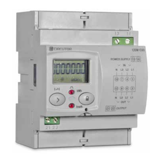
- Page 1 Multifunctional energy meter CEM-C20 CEM-C20 MID INSTRUCTION MANUAL (M016B01-03-17B)
- Page 2 CEM-C20 Instruction Manual...
-
Page 3: Safety Precautions
CIRCUTOR, SA reserves the right to modify features or the product manual without prior notifi cation. DISCLAIMER CIRCUTOR, SA reserves the right to make modifi cations to the device or the unit specifi ca- tions set out in this instruction manual without prior notice. -
Page 4: Table Of Contents
CEM-C20 CONTENTS SAFETY PRECAUTIONS ��������������������������������������������������������������������������������������������������������������������������������������� 3 DISCLAIMER ����������������������������������������������������������������������������������������������������������������������������������������������������������3 CONTENTS �������������������������������������������������������������������������������������������������������������������������������������������������������������4 REVISION LOG �������������������������������������������������������������������������������������������������������������������������������������������������������5 1�- VERIFICATION UPON RECEPTION ����������������������������������������������������������������������������������������������������������������� 6 2�- PRODUCT DESCRIPTION �������������������������������������������������������������������������������������������������������������������������������� 6 3�- UNIT INSTALLATION ���������������������������������������������������������������������������������������������������������������������������������������� 7 3�1�- PRELIMINARY RECOMMENDATIONS ����������������������������������������������������������������������������������������������������� 7 3�2�- INSTALLATION ������������������������������������������������������������������������������������������������������������������������������������������ 8 3�3�- UNIT TERMINALS �������������������������������������������������������������������������������������������������������������������������������������� 8 3�4�- CONNECTION DIAGRAM ��������������������������������������������������������������������������������������������������������������������������... -
Page 5: Revision Log
CEM-C20 REVISION LOG Table 1: Revision log� Date Revision Description 07/14 M016B01-03-14A Initial Version Changes in the following sections: 11/14 M016B01-03-14B 4.2. - 4.6 Changes in the following sections: 05/15 M016B01-03-15A 2 - 3.5 - 4.4.1. - 4.4.2. - 4.5. - 4.6. - 4.7. - 5... -
Page 6: 1�- Verification Upon Reception
CIRCUTOR's after-sales service. 2�- PRODUCT DESCRIPTION The CEM-C20 static three-phase energy meter measures class B active energy (EN50470) and (optional) class 2 reactive energy (IEC 62053-23), with optional optical communications for expansion with other modules installed on a DIN rail with a service port. -
Page 7: 3�- Unit Installation
The CEM-C20 unit must be installed by authorised and qualified staff. The power supply plug must be disconnected and measuring systems switched off before han- dling, altering the connections or replacing the unit. -
Page 8: 3�2�- Installation
Do not use the unit until it is fully installed. 3.3.- UNIT TERMINALS Table 2:List of CEM-C20 terminals� Unit terminals 1 : L1, Current input (voltage) L1 10: N, Neutral input... -
Page 9: 3�4�- Connection Diagram
CEM-C20 3.4.- CONNECTION DIAGRAM Power Supply Figure 2: Connection diagram, CEM-C20� Instruction Manual... -
Page 10: 3�5�- Connections
CEM-C20 3.5.- CONNECTIONS The CEM-C20 has terminal covers to cover the top of the terminal box and the fixing screws Figure 3 Figure 3: Terminal covers of the CEM-C20� The fixing screws are of the mixed type, allowing the use of PZ2 and flat head screwdrivers. - Page 11 CEM-C20 When the unit is connected to the mains, attach the safety label ( ) to Figure 5 terminals 13 and 14, in order to prevent the risk of electric shock caused by an involuntary direct contact. Figure 5: Attaching the safety label�...
-
Page 12: 4�- Operation
Power factor, PF 4.1.- BUTTON FUNCTIONS The CEM-C20 has 1 button that allows you to browse the different screens and configure the unit. Button functions on the measuring screens ( Table 4 Table 4: Button functions on the measuring screens�... -
Page 13: 4�3�- Led Indicators
The LEDs will remain lit when the current is lower than the energy meter start-up current. Once the start-up current is exceeded (due to active or reactive power consumption) the LEDs are turned off and emit impulses that are proportional to the measured energy. Active LED Reactive LED Figure 7:LED Indicators of the CEM-C20� Instruction Manual... -
Page 14: 4�4�- Display Modes
4�4�1� DISPLAY IN STANDBY MODE With the display in standby mode, all of the information is presented in cyclic form without any need to perform any action on the CEM-C20 buttons. 7 different parameters are displayed in this mode, see... - Page 15 CEM-C20 Table 5 ( Continuation ): Standby mode displays Screen Parameters Reactive energy quadrant C+ total Only displayed if the reactive energy display option has been selected in the setup menu. ( see “4.7.6. Diplay” ). The standby mode is activated again when no button is pressed for 60 seconds.
-
Page 16: 4�4�2� Display In Reading Mode
CEM-C20 4�4�2� DISPLAY IN READING MODE The reading mode is activated by a long press on the button. In reading mode you can: View the voltage, current, active power, apparent power and power factor of the installation. View the energies of the partial energy meters. -
Page 17: 4�5�- Instantaneous Value Display
CEM-C20 4.5.- INSTANTANEOUS VALUE DISPLAY To open the screens where the instantaneous value are viewed, long press the key on the display in standby mode. The home screen is displayed Figure 9 Figure 9: Instantaneous Value main screen� Long press the button to open the different screens. - Page 18 CEM-C20 Table 6 ( Continuation ): Instantaneous value screens� Screen Parameters L3 Current Active three-phase power Reactive three-phase power Apparent three-phase power L1 Power Factor L2 Power Factor L3 Power Factor Hours of operation from manufacture The unit must be connected to the L1 phase to calculate the reactive power.
-
Page 19: 4�6�- Partial Energy Display
CEM-C20 4.6.- PARTIAL ENERGY DISPLAY NB: The partial energy display menu is only displayed if the partial energy display option has been selected in the setup menu ( see “ 4.7.6. Display” ) Long press the key in the standby mode screen to open these display screens. Short press... - Page 20 CEM-C20 Table 7 ( Continuation ): Partial energy screens� Screen Parameters Partial reactive energy, quadrant 3 ( C-) Only displayed in the 4-quadrant version. Partial reactive energy, quadrant 4 ( C+) Hours in partial operation (since the last partial reset )
-
Page 21: 4�7�- Configuration
CEM-C20 4.7.- CONFIGURATION In the setup menu you can: Program the weight and type of impulse output Program the communications. Program the display screen. Program the cost of the energy and the CO emissions Delete the partial energy meters. -
Page 22: 4�7�2� Impulse Output Type
CEM-C20 Figure 12: Validation screen� After a few seconds viewing the screen shown on , the system returns to the Impulse Figure 12 output weight programming main screen. Minimum value: 99999. Maximum value: 0. Short press the button to access the next programming step. -
Page 23: 4�7�4� Transmission Speed (Baud Rate)
CEM-C20 To write or modify the value, short press the button repeatedly, increasing the value of the flashing digit. When the desired value is shown on the screen, move onto the next digit with a long press on button, allowing the remaining values to be modified. -
Page 24: 4�7�5� Type Of Communications
CEM-C20 4�7�5� Type of communications Note: This is only displayed if there is a (communications interface for the CEM CEM M-RS485 family of units) connected to the unit. This is the home screen for selecting the number of bits, the parity and the number of stop bits of the communications frame. - Page 25 CEM-C20 Long press to view the options. The possible options are: Yes, if you want to view the partial energy. No, if you select this option, the unit stops recording the partial energy. A display view is not provided and the value displayed by communications is 0.
-
Page 26: 4�7�7� Backlight
CEM-C20 The possible options are: Yes, if you want a display view of the efficiency screens (cost of energy and CO emissions). No, if you select this option, the unit stops recording the efficiency factors. A display view is not provided and the value displayed by communications is 0. -
Page 27: 4�7�8� Energy Cost
CEM-C20 4�7�8� Energy cost NB: It is only displayed if the efficiency factors display has been selected. This is the home screen for entering the energy cost per kWh. Long press the button to view the value to be programmed. -
Page 28: 4�7�10� Partial Energy Meter Deletion
CEM-C20 To write or modify the value, short press the button repeatedly, increasing the value of the flashing digit. When the desired value is shown on the screen, move onto the next digit with a long press on button, allowing the remaining values to be modified. -
Page 29: 4�8�- Manufacturer Information Screen
CEM-C20 4.8.- MANUFACTURER INFORMATION SCREEN Long press the button in the standby mode screen to open these display screens. Short press the button to display the manufacturer information home screen, Figure 13 Figure 13: Manufacturer information home screen� Long press the button to open the different screens. -
Page 30: 4�9�- Impulse Output
CEM-C20 Table 8 ( Continuation ): Manufacturer information screens� Screen Parameters Reactive energy with resolution varh 32-bit CRC The screen is displayed if there is a CEM M-RS485 (communications interface for units of the CEM family) connected to the unit. -
Page 31: 5�- Technical Features
CEM-C20 5�- TECHNICAL FEATURES Power supply Mode Auxiliary CEM-C20 MID CEM-C20 Rated voltage 230 V ~ 230 V ~ / 400 V ~ Tolerance ± 20 % Frequency 50...60Hz < 2 W Consumption < 10VA (In, Vref (without auxiliary services)) - Page 32 Relative humidity (non-condensing) 5 ... 95% Maximum altitude 2,000 m Mechanical features Dimensions ( Figure 14) in mm. IEC60715 Weight 340 g. Enclosure EN50022 IP 51 installed Protection degree IP40 in terminal area Figure 14: Dimensions of the CEM-C20� Instruction Manual...
- Page 33 CEM-C20 Standards Electrical energy metering equipment (AC)� Part 1: General require- ments, tests and test conditions� Metering equipment (indexes of class- UNE EN 50470-1:2007 es A, B and C) Electrical energy metering equipment (AC)� Part 3: Particular require- UNE EN 50470-3:2007 ments.
-
Page 34: 6�- Maintenance And Technical Service
• CIRCUTOR accepts no liability due to the possible damage to the unit or other parts of the installation, nor will it cover any possible sanctions derived from a pos- sible failure, improper installation or “improper usage”... -
Page 35: 8�- Ce Certificate
CEM-C20 8�- CE CERTIFICATE Instruction Manual... - Page 36 CEM-C20 Instruction Manual...
- Page 37 CEM-C20 Instruction Manual...
- Page 38 CIRCUTOR, SA Vial Sant Jordi, s/n 08232 -Viladecavalls (Barcelona) Tel.: (+34) 93 745 29 00 - Fax: (+34) 93 745 29 14 www.circutor.com central@circutor.com...
Need help?
Do you have a question about the CEM-C20 and is the answer not in the manual?
Questions and answers