
Subscribe to Our Youtube Channel
Related Manuals for Circutor CEM-C12


Summary of Contents for Circutor CEM-C12
- Page 1 Multifunctional Energy Meter CEM-C12 CEM-C12-MID INSTRUCTION MANUAL (M336B01-03-21A)
- Page 2 CEM-C12 Instruction Manual...
-
Page 3: Safety Precautions
CIRCUTOR, SA reserves the right to make modifications to the device or the unit specifications set out in this instruction manual without prior notice. CIRCUTOR, SA on its web site, supplies its customers with the latest versions of the device specifica- tions and the most updated manuals. -
Page 4: Table Of Contents
CEM-C12 CONTENTS SAFETY PRECAUTIONS ���������������������������������������������������������������������������������������������������������������������������������������������������������3 DISCLAIMER ��������������������������������������������������������������������������������������������������������������������������������������������������������������������������3 CONTENTS �����������������������������������������������������������������������������������������������������������������������������������������������������������������������������4 REVISION LOG �����������������������������������������������������������������������������������������������������������������������������������������������������������������������5 SYMBOLS �������������������������������������������������������������������������������������������������������������������������������������������������������������������������������5 1�- VERIFICATION UPON RECEPTION ������������������������������������������������������������������������������������������������������������������������������������6 2�- PRODUCT DESCRIPTION �������������������������������������������������������������������������������������������������������������������������������������������������6 3�- DEVICE INSTALLATION ����������������������������������������������������������������������������������������������������������������������������������������������������7 3�1�- PRELIMINARY RECOMMENDATIONS ������������������������������������������������������������������������������������������������������������������������7 3�2�- INSTALLATION ���������������������������������������������������������������������������������������������������������������������������������������������������������8 3�3�- DEVICE TERMINALS �������������������������������������������������������������������������������������������������������������������������������������������������9 3�4�- CONNECTION DIAGRAM �������������������������������������������������������������������������������������������������������������������������������������������9 4�- OPERATION �������������������������������������������������������������������������������������������������������������������������������������������������������������������... -
Page 5: Revision Log
CEM-C12 REVISION LOG Table 1: Revision log� Date Revision Description 03/22 M336B01-03-21A Initial Version SYMBOLS Table 2: Symbols� Symbol Description In compliance with the relevant European directive. Device covered by European directive 2012/19/EC. At the end of its useful life, do not leave the unit in a household waste container. -
Page 6: 1�- Verification Upon Reception
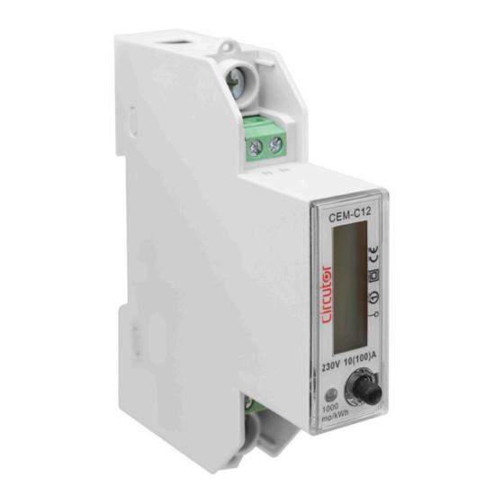
CIRCUTOR's after-sales service. 2.- PRODUCT DESCRIPTION The CEM-C12 static single-phase energy meter measures class 1 (IEC 62053-21) / class B (EN50470), with multifunction, RS-485 communications and DIN rail standard installations. It is the ideal solution for residential and commercial installations. -
Page 7: 3�- Device Installation
The CEM-C12 device must be installed by authorised and qualified staff. The measuring systems switched off before handling, altering the connections or replacing the device. -
Page 8: 3�2�- Installation
CEM-C12 3�2�- INSTALLATION Terminals, opening covers or removing elements can expose parts that are hazardous to the touch while the device is powered. Do not use the device until it is fully installed. Installation instruction: 1�- Choose 35mm standard DIN rail (the length is confirmed by yourself), fixed them in the location which are waiting for installation. -
Page 9: 3�3�- Device Terminals
CEM-C12 3�3�- DEVICE TERMINALS Table 3:List of CEM-C12 terminals� Device terminals 1 : L, Input, connected to the mains phase B-: B-, RS-485 connection 3: LOAD, Output S: S, RS-485 connection N: N, Input, connected to neutral A+: A+, RS-485 connection Figure 4:Terminals of the CEM-C12�... -
Page 10: 4�- Operation
CEM-C12 4.- OPERATION The CEM-C12 measures in the 4 quadrants (consumption and generation). Single-phase Single-phase Three-phase Three-phase 90º Inductive Capacitive 180º 0º Inductive Capacitive Single-phase Three-phase Single-phase Three-phase -90º Generation Consumption Power Power Figure 6: Sign convention� Table 4: CEM-C12 Measurement parameters�... - Page 11 15 minutes. The result would be 60 values per hour. Integration period Integration period Sliding window Calculation time Integration period Figure 8:Sliding Window� The CEM-C12 calculates the Maximum demand with a fixed window and a 15-minute integration period Instruction Manual...
-
Page 12: 4�1�- Keyboard Functions
CEM-C12 4�1�- KEYBOARD FUNCTIONS The CEM-C12 has one key to move around the different screens and configure the communications Figure 9 Display Keyboard Figure 9: CEM-C12, description� 4�2�- DISPLAY The device has an LCD where all parameters are displayed ( Figure 9 4�3�- LED INDICATORS... - Page 13 CEM-C12 5.- DISPLAY The data can be displayed through 2 methods: Automatically, the device automatically switches screens every 5 seconds. Pressing the key. Table 5: Display� Screen Parameters Total Active Energy (consumed + generated) (kWh) Inductive Reactive Energy consumed...
-
Page 14: 6�- Configuring Rs-485 Communications
CEM-C12 6.- CONFIGURING RS-485 COMMUNICATIONS To go into the communications configuration menu, press > 5 seconds while in any display screen. > 5s > 3s Peripheral number > 3s Modbus Baud rate > 3s Data bits > 3s Parity >... -
Page 15: 6�1�- Peripheral Number
CEM-C12 6�1�- PERIPHERAL NUMBER This screen enables peripheral number configuration. To go into the configuration screen, press > 3 seconds. > 3s Press to change the digit value. Press > 3 seconds to change digits. Press > 6 seconds to save the change. The screen shown in... -
Page 16: 6�3�- Data Bits
CEM-C12 Press to skip to the next programming step. 6�3�- DATA BITS This screen shows the number of data bits. Press > 3 seconds to open the configuration screen. > 3s Note: This parameter cannot be modified. Press to skip to the next programming step. - Page 17 CEM-C12 Press > 6 seconds to save the change. The screen shown in indicates that the changes Figure 11 have been saved correctly. Configuration values Table 9: Configuration values: Stop bits� Stop bits 1 stop bit Possible values 2 stop bit Press ...
-
Page 18: 7�- Rs-485 Communications
CEM-C12 7.- RS-485 COMMUNICATIONS The CEM-C12 has one RS-485 communications port to view the measurement data and configure the devices. The visualization and configuration can also be done through the CIRCUTOR PowerStudio software. Note: Default values of RS-485 communication: No. of peripheral 1, 9600 bps, No parity, 8 data bits and 1 stop bit. -
Page 19: 7�2�- Modbus Commands
CEM-C12 Address: 01, Peripheral number: 1 in decimals. Function: 10, Writing function. Initial Register: 0064, Address of the Baud rate parameter. No of registers: 0001, number of registers write. No of bytes: 02, number of bytes write. Value: 0004, 0004 → 9600 bps. - Page 20 CEM-C12 Tabla 11 (Continuación) : Mapa de memoria Modbus (Tabla 2) Modbus Parameter Function Units address Total active Energy (Consumed + Generated) 5B - 5C kWh x 100 Total reactive energy (Consumed + Generated) 5D - 5E kvarh x 100 Table 12: Modbus memory map (Table 3)�...
-
Page 21: 8�- Technical Features
CEM-C12 8.- TECHNICAL FEATURES Power supply Mode Self-powered Voltage Measurement Connection Single-phase Reference voltages 230 V ~ CEM-C12 50 / 60 Hz Frequency CEM-C12-MID 50 Hz Power consumption ≤ 10 VA, ≤ 0.4 Wh Current measurement Current 0.25 ... 5 A... - Page 22 Electricity metering equipment (a�c�) -- Part 3: Particular requirements - Static me- EN 50470-3 ters for active energy (class indexes A, B and C) CEM-C12-MID MID (Measuring Instruments Directive): EU Directive 2014/32/EU on Measuring Instruments Annex II, Module B 47.8 Figure 12: Dimensions of the CEM-C12� Instruction Manual...
-
Page 23: 9�- Maintenance And Technical Service
CEM-C12 9.- MAINTENANCE AND TECHNICAL SERVICE In the case of any query in relation to device operation or malfunction, please contact the CIRCUTOR, SA Technical Support Service. Technical Assistance Service Vial Sant Jordi, s/n, 08232 - Viladecavalls (Barcelona) Tel: 902 449 459 ( España) / +34 937 452 919 (outside of Spain) email: sat@circutor.com... -
Page 24: 11�- Ce Certificate
CEM-C12 11.- CE CERTIFICATE Instruction Manual... - Page 25 CEM-C12 Instruction Manual...
- Page 26 CEM-C12 Instruction Manual...
- Page 27 CEM-C12 Instruction Manual...
- Page 28 CIRCUTOR, SA Vial Sant Jordi, s/n 08232 -Viladecavalls (Barcelona) Tel.: (+34) 93 745 29 00 - Fax: (+34) 93 745 29 14 www.circutor.com central@circutor.com...
Need help?
Do you have a question about the CEM-C12 and is the answer not in the manual?
Questions and answers