Table of Contents
Advertisement
Quick Links
Advertisement
Table of Contents

Related Manuals for Circutor CEM-C5


Summary of Contents for Circutor CEM-C5
- Page 1 Energy Meter CEM-C5 INSTRUCTION MANUAL (M218B01-03-18A)
- Page 2 CEM-C5 Instruction Manual...
-
Page 3: Safety Precautions
CIRCUTOR, SA reserves the right to modify features or the product manual without prior notifi cation. DISCLAIMER CIRCUTOR, SA reserves the right to make modifi cations to the device or the unit specifi ca- tions set out in this instruction manual without prior notice. -
Page 4: Table Of Contents
CEM-C5 CONTENTS SAFETY PRECAUTIONS ��������������������������������������������������������������������������������������������������������������������������������������� 3 DISCLAIMER ����������������������������������������������������������������������������������������������������������������������������������������������������������3 CONTENTS �������������������������������������������������������������������������������������������������������������������������������������������������������������4 REVISION LOG �������������������������������������������������������������������������������������������������������������������������������������������������������5 SYMBOLS ���������������������������������������������������������������������������������������������������������������������������������������������������������������5 1�- VERIFICATION UPON RECEPTION ����������������������������������������������������������������������������������������������������������������� 6 2�- PRODUCT DESCRIPTION �������������������������������������������������������������������������������������������������������������������������������� 6 3�- DEVICE INSTALLATION ����������������������������������������������������������������������������������������������������������������������������������� 7 3�1�- PRELIMINARY RECOMMENDATIONS ����������������������������������������������������������������������������������������������������� 7 3�2�- INSTALLATION ������������������������������������������������������������������������������������������������������������������������������������������ 8 3�3�- DEVICE TERMINALS ���������������������������������������������������������������������������������������������������������������������������������... -
Page 5: Revision Log
CEM-C5 REVISION LOG Table 1: Revision log� Date Revision Description 04/18 M218B01-03-18A Initial Version SYMBOLS Table 2: Symbols� Symbol Description In compliance with the relevant European directive. Device covered by European directive 2012/19/EC. At the end of its useful life, do not leave the unit in a household waste container. -
Page 6: 1�- Verification Upon Reception
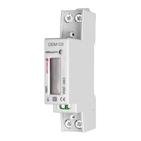
If any problem is noticed upon reception, immediately contact the transport company and/or CIRCUTOR's after-sales service. 2�- PRODUCT DESCRIPTION The CEM-C5 is a single-phase energy meter used to measure class 1 active energy, with im- pulse output and DIN rail standard installations. The device features: - Impulse output. -
Page 7: 3�- Device Installation
The CEM-C5 device must be installed by authorised and qualified staff. The measuring systems switched off before handling, altering the connections or replacing the device. -
Page 8: 3�2�- Installation
CEM-C5 3.2.- INSTALLATION Terminals, opening covers or removing elements can expose parts that are haz- ardous to the touch while the device is powered. Do not use the device until it is fully installed. Installation instruction: 1�- Choose 35mm standard DIN rail (the length is confirmed by yourself), fixed them in the location which are waiting for installation. -
Page 9: 3�3�- Device Terminals
500V or less than 500 V AC and DC power distribution system. The temperature for the data listed in the above table is 35ºC, the safe carrying capacity value for the wire on single cover. 3.3.- DEVICE TERMINALS Table 4:List of CEM-C5 terminals� Device terminals 1 : L(IN), Input, connected to the mains phase... -
Page 10: 3�4�- Connection Diagram
CEM-C5 3.4.- CONNECTION DIAGRAM L (OUT) L (IN) 21 20 Figure 5: Connection diagram, CEM-C5� Instruction Manual... -
Page 11: 4�- Operation
The device has one verification LED, to verify the active energy� The weight of the LED is 1000 imp/kWh ( Figure 6 4.3.- IMPULSE OUTPUT The CEM-C5 has a impulse output, terminals 20 and 21 of Table 4. Instruction Manual... -
Page 12: 5�- Technical Features
CEM-C5 5�- TECHNICAL FEATURES Power supply Mode Self-powered Voltage Measurement Connection Single-phase Reference voltages 230 V ~ Frequency 50 Hz Power consumption ≤ 8 VA, ≤ 0.4 Wh Current measurement Current 0.25 - 5 A Maximum current (Imax) 50 A Starting current 0.004 Ib... - Page 13 CEM-C5 Figure 7: Dimensions of the CEM-C5� Instruction Manual...
-
Page 14: 6�- Maintenance And Technical Service
• CIRCUTOR accepts no liability due to the possible damage to the unit or other parts of the installation, nor will it cover any possible sanctions derived from a pos- sible failure, improper installation or “improper usage”... -
Page 15: 8�- Ce Certificate
CEM-C5 8�- CE CERTIFICATE Instruction Manual... - Page 16 CEM-C5 Instruction Manual...
- Page 17 CEM-C5 Instruction Manual...
- Page 18 CIRCUTOR, SA Vial Sant Jordi, s/n 08232 -Viladecavalls (Barcelona) Tel.: (+34) 93 745 29 00 - Fax: (+34) 93 745 29 14 www.circutor.com central@circutor.com...
Need help?
Do you have a question about the CEM-C5 and is the answer not in the manual?
Questions and answers