MrCool DIY E Star Series Owners & Installation Manual
Hide thumbs
Also See for DIY E Star Series:
- Installation & owner's manual (60 pages) ,
- Troubleshooting manual (55 pages) ,
- Owners & installation manual (41 pages)
Table of Contents

Related Manuals for MrCool DIY E Star Series


Summary of Contents for MrCool DIY E Star Series
- Page 1 Please read this manual carefully before installation and keep it for future reference. Owner & Installation Manual E Star™ Series ® Please read this manual carefully before installation and keep it for future reference. V100220...
-
Page 2: Table Of Contents
Manual Operation ........................Care and Maintenance DISCLAIMER: You are assuming the risk by handling materials containing refrigerants under pressure that if not handled properly, refrigerant can cause bodily injury. If you do not feel comfortable conducting this installation Page 1 mrcool.com... - Page 3 1. Installation location........15 4. Prepare refrigerant piping ....18 7. Wrap piping and cables......22 8. Mount indoor unit........22 Outdoor Unit Installation ..1. Installation location ......23 2. Install drain joint .........24 Refrigerant Piping Connections......27 Electrical Connections ........31 Test Run.............34 mrcool.com Page 2...
-
Page 4: Safety Precautions
If you do not feel comfortable conducting this installation DO NOT DO NOT When connecting refrigerant piping, let substances or gases other than the refrigerant DO NOT unit at all times. Manual. mrcool.com Page 3... - Page 5 Safety Precautions wiring rules. DO NOT combustible materials. DO NOT DO NOT DO NOT DO NOT Note about Flourinated Gasses: the unit itself. mrcool.com Page 4...
-
Page 6: Parts Overview
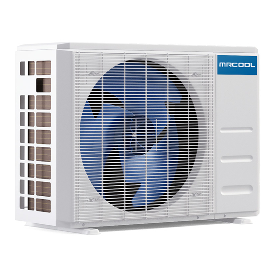
Air outlet bottom Fresh Air Filter Air inlet rear Air inlet si e Electrical Access Air outlet (Exterior / Condenser) NOTE ON ILLUSTRATIONS Illustrations in this manual are for explanatory purposes. The actual shape of your unit may vary. mrcool.com Page 5... - Page 7 NOTE: A guide for using the infrared remote - “Remote Manual” - is included in this literature package. 4. Energy Saving Mode: Displays when Energy Saving Feature is active. Not available when the unit does not have Energy Saving Mode mrcool.com...
-
Page 8: Accessories
Fixing screw for remote ST2.9 x 10 Optional Parts Dry battery AAA.LR03 Seal (Only for use Drain joint when elevated) (Sealant for Wall Sleeve) Neoprene Note: Illustrations are for explanatory purposes only - The actual shape may vary. mrcool.com Page 7... - Page 9 Please read this manual carefully before installation and keep it for future reference. Owner’s Manual Owner & Installation Manual E-Star™ DIY Series For more details visit www.MrCool.com Please read this manual carefully before installation and keep it for future reference. Remote Control User Manual Remote Control Manual For more details visit www.MrCool.com...
-
Page 10: Operating Instructions
If the unit is operational, continue pressing the Manual Control Button (Forced cooling) CAUTION • This switch is used for testing purposes only. Please do not use it unless necessary. Fig 2.1 •To restore the remote control operation, use the remote control directly. mrcool.com Page 9... - Page 11 After a quick restart, the vertical louver may Open angle of the vertical louver should not be COOLING and HEATING performance. Range Page 10 mrcool.com...
- Page 12 Temperature hour hour supplement heating with other appliances. Heating Optimal Operation: curtains while · heating also helps keep the heat in · · performance. · Doors and function. windows should be kept closed · the unit. · mrcool.com Page 11...
- Page 13 Refrigerant Leakage Detection (optional): Louver Angle Memory Function (optional): Anti-Mildew Function (optional): Optimal Operation: Wireless Smart Control Function: Clean Air Filter Reminder (optional): LED button on Replace Air Filter Reminder (optional): LED button Mute Function (optional): Press the LED mrcool.com Page 12...
- Page 14 DO NOT handling the sharp metal edges. shrink. Dry it in the shade. DO NOT use water to clean inside the air conditioner. Exposure to water can destroy the insulation, leading to possible electric shock. breaker. DO NOT mrcool.com Page 13...
- Page 15 Care and Maintenance lowering the bottom into place. Preparation for Extended non-Operation: the circuit. Pre-Season Inspection: mrcool.com Page 14...
-
Page 16: Indoor Unit Installation
(while facing the unit). After piping and signal wiring are installed, use provid- Strong enough to support the weight of ed neoprene to pack the space making it the unit airtight. mrcool.com Page 15... - Page 17 When drilling the wall hole, be sure to avoid holes in the wall and insert the sleeve anchors wires, plumbing, nails, screws, and other provided. Secure the mounting plate to the sensitive components. wall by tightening the screws directly into the clip anchors. mrcool.com...
- Page 18 • Width of indoor unit relative to plate • Height of indoor unit relative to plate • Recommended position of wall hole • Relative distances between screw holes • Do not attempt a left rear wall hole. Correct orientation of Mounting Plate mrcool.com Page 17...
-
Page 19: Prepare Refrigerant Piping
(30-50mm) (30-50mm) Move to left or right CAUTION Be extremely careful not to dent or damage the piping while bending them away from the unit. Dents in the piping will affect performance. mrcool.com Page 18... - Page 20 Their seal can not be guaranteed if they are installed on more than one occasion. This will also void the warranty. indoor unit are the same. Place the screw connector on the IMPORTANT: Before you continue, it is essential that you read the following instructions carefully. • mrcool.com Page 19...
- Page 21 NOTE: must be placed outside of the room. Using the wall hole sleeve, cap and neoprene to seal the ® wall hole. Both power cable and signal cable should be protected by conduit. mrcool.com Page 20...
- Page 22 NOT CORRECT factory installed hollow center rubber plug is DO NOT place the end in the unused drain hole. of the drain hose in water or in containers that collect water. This will prevent proper drainage. Fig. 4.5d mrcool.com Page 21...
-
Page 23: Wrap Piping And Cables
Indoor Unit outdoor unit, Space behind unit Step 4. Refrigerant piping Insulation tape foreign material from entering the pipes. Drain hose DRAIN HOSE MUST BE ON BOTTOM SIGNAL CABLE PROTECTION mounting plate. Fig. 5.7 for Fig. 5.7 mrcool.com Page 22... - Page 24 Noise from the unit will not disturb others In a location exposed to a excessive amounts of salty air Protected from prolonged periods of direct In a location that exposes the unit to large sunlight or rain amounts of forced water mrcool.com Page 23...
- Page 25 IN COLD CLIMATES In cold climates, make sure that the drain hose is as vertical as possible to ensure swift water drainage. If water drains too slowly, it bottom of the unit. Note that there are two mrcool.com Page 24...
- Page 26 540 mm 26.5 in. DIY-24-HP-C-230B 673 mm 403 mm 26.5 in. DIY-36-HP-C-230B 673 mm 403 mm concrete mounting platform, do the following: replace the nuts. chart. WHEN DRILLING INTO CONCRETE, EYE PROTECTION IS RECOMMENDED AT ALL TIMES. holes. Page 25 mrcool.com...
- Page 27 The wall must be able to support at least four times the weight of the unit. ATION OF WALL- MOUNTED UNIT If allowed, you can install the wall-mounted unit with rubber gaskets to reduce vibra- tion and noise. mrcool.com...
- Page 28 IMPORTANT refrigerant pipes until before IMPORTANT Since the coupling works with tapping rings, it may leak if you undo and reconnect the pipes. This will also void the warranty. NOTE: to connect the line set. mrcool.com Page 27...
- Page 29 HVAC torque wrench) and that a socket style wrench cannot be used here. Stamp Outer Diameter of Pipe (in/mm) (lb·ft / N·m) (lb·ft / N·m ) N·m N·m N·m N·m N·m N·m N·m N·m mrcool.com Page 28...
- Page 30 Refrigerant Piping Connection CAUTION wrench. NOTE NOTE mrcool.com Page 29...
-
Page 31: Refrigerant Piping Connections
Do not connect another appliance to the same circuit. Make sure to properly ground the air conditioner. Do not let wires touch or rest against refrigerant tubing, the compressor, or any moving parts within the unit. combustible materials. mrcool.com Page 30... -
Page 32: Electrical Connections
This is dangerous and can cause the air conditioning unit to malfunction. Make sure you clearly distinguish the Live (”L”) Wires from the other wires. All wiring must be performed in accordance with the wiring diagrams the images shown here. mrcool.com Page 31... - Page 33 ALL WIRING MUST BE PERFORMED STRICTLY designed with a fuse to provide overcurrent IN ACCORDANCE WITH THE WIRING DIAGRAM LOCATED AS SHOWN IN FIG 7.2. printed on the circuit board. EXAMPLE EXAMPLE Outdoor unit: or metal parts. screw it in place. mrcool.com Page 32...
- Page 34 BEFORE TEST RUN Note: Soap and Water Method DURING TEST RUN Leak Detector Method tion manual for proper usage instructions. AFTER PERFORMING GAS LEAK CHECKS points DO NOT leak, replace the valve cover on the outside unit. Note: mrcool.com Page 33...
- Page 35 Press the button to scroll through the function properly • – Select lowest possible temperature function properly • – Select highest possible temperature Indoor unit louvers rotate properly Indoor unit responds to remote control mrcool.com Page 34...
-
Page 36: Test Run
Press it 2 times to select the COOL function. See Fig. product on ® 3.Perform Test Run as normal. the partner site where you purchased it from actual customers like you are invaluable to a growing company like ours. mrcool.com Page 35... - Page 37 If not the case, contact a local dealer or your installation contractor. Interference from cell phone towers and remote boosters may cause the Operation is erratic, unit to malfunction. unpredictable or unresponsive Press the ON/O mrcool.com...
- Page 38 DO NOT ATTEMPT TO CORRECT · Burning odor THESE ITEMS YOURSELF! · Loud or abnormal sounds · A power fuse or circuit breaker trips frequently · Water or other objects fall into or out of the unit PROFESSIONAL IMMEDIATELY mrcool.com Page 37...
- Page 39 (only for 9k,12k models) 5 times Inverter compressor drive error Discharge temp sensor USB Smart Controller module not installed general conventions. . Wires and terminals are numbered to match accordingly. O(light) (flash) X(off) mrcool.com Page 38...
- Page 40 E Star Series ® ™ Consult with the sales agency or manufacturer for details.