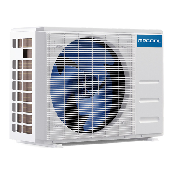
MrCool DIY E Star Series Owners & Installation Manual

MrCool DIY E Star Series Owners & Installation Manual

Hide thumbs Also See for DIY E Star Series:

Advertisement

Please read this manual carefully before installation and keep it for future reference.
Owner & Installation
Manual
DIY
E Star
Series
®
Please read this manual carefully before installation and keep it for future reference.

Advertisement

Table of Contents
loading

Summary of Contents for MrCool DIY E Star Series

  • Page 1 Please read this manual carefully before installation and keep it for future reference. Owner & Installation Manual E Star Series ® ™ Please read this manual carefully before installation and keep it for future reference.
  • Page 2: Table Of Contents

    Airflow Directional Control ....................How the A/C & Heat Pump Work ..................Special Functions ........................Care and Maintenance Before Maintenance ......................Cleaning the Unit ........................Cleaning the Air Filter(s) ......................Preparation for Extended Non-Operation ................Pre-Season Inspection ......................Page 1 mrcool.com...
  • Page 3 8. Mount indoor unit........22 Outdoor Unit Installation ..1. Installation location ......23 2. Install drain joint .........24 3. Anchor outdoor unit ......25 Refrigerant Piping Connections......27 Electrical Connections ........31 Electrical and Gas Leak Checks.......33 Test Run.............34 Troubleshooting..........36 EU Disposal Guidelines........39 mrcool.com Page 2...
  • Page 4: Safety Precautions

    For all electrical work, follow all appropriate wiring standards, regulations, and the Installation Manual. You must use an independent circuit to supply power. Do not connect other appliances to the same circuit. Insufficient electrical capacity or defects in electrical work can cause electrical shock or fire. mrcool.com Page 3...
  • Page 5 Product uninstallation and recycling must be performed by a certified technician. If the system has a leak-detection system installed, it should be checked for leaks at least every 12 months. Keep a record of all leak checks for the lifetime of the unit. mrcool.com Page 4...
  • Page 6: Parts Overview

    Indoor Unit Air outlet Refrigerant Pipe Connection and Stop Valve (under cover) Outdoor Unit (Exterior / Condenser) Fig. 1.1 NOTE ON ILLUSTRATIONS Illustrations in this manual are for explanatory purposes. The actual shape of your unit may vary. mrcool.com Page 5...
  • Page 7: Display Window

    NOTE: A guide for using the infrared remote - “Remote Manual” - is included in this literature package. 4. Energy Saving Mode: Displays when Energy Saving Feature is active. Not available when the unit does not have Energy Saving Mode mrcool.com Page 6...
  • Page 8: Accessories

    Remote control holder Dry battery AAA.LR03 Air freshening filter Seal Allen wrench Drain joint (Only for use when elevated) (Sealant for Wall Sleeve) Neoprene Note: Illustrations are for explanatory purposes only - The actual shape may vary. mrcool.com Page 7...
  • Page 9 Please read this manual carefully before installation and keep it for future reference. Owner’s Manual Owner & Installation Manual E-Star™ DIY Series For more details visit www.MrCool.com Please read this manual carefully before installation and keep it for future reference. Remote Control User Manual Remote Control Manual For more details visit www.MrCool.com...
  • Page 10: Operating Instructions

    Close the panel firmly to its original position. Button (Forced cooling) CAUTION • This switch is used for testing purposes only. Please do not use it unless necessary. Fig 2.1 •To restore the remote control operation, use the remote control directly. mrcool.com Page 9...
  • Page 11: Airflow Directional Control

    After a quick restart, the vertical louver may remain static for approximately 10 seconds. Open angle of the vertical louver should not be set too small, as it will restrict airflow and reduce COOLING and HEATING performance. Range fig 2.4 Page 10 mrcool.com...
  • Page 12: How The A/C & Heat Pump Work

    · Do not put any objects near the air inlets / outlets. Doing so would impair performance and possible shut down the unit. · Inspect the air filters periodically, and clean them as needed. mrcool.com Page 11...
  • Page 13: Special Functions

    “nF” indicator will flash again when you restart the unit. Mute Function (optional): Press the LED button on the remote to turn off the LED display and silence the buzzer of the indoor unit, creating a quiet comfortable environment. mrcool.com Page 12...
  • Page 14: Care And Maintenance

    At a certain angle, there will be an audible click and the lid becomes self-supporting. For some models, suspension bars are provided and required to prop up the lid. Use the filter tabs to lift the filter slightly upward and then toward FilterTab you. mrcool.com Page 13...
  • Page 15: Preparation For Extended Non-Operation

    Pre-Season Inspection: After prolonged non-operation perform the following: Check for Damaged or Disconnected Wires. Clean the Indoor Unit and Filters Check for Water and Oil Leaks Check for Blockages in Airflow Inlet and Outlet Replace Batteries mrcool.com Page 14...
  • Page 16: Indoor Unit Installation

    Strong enough to support the weight of right. After piping and signal wiring are the unit installed, use provided neoprene to pack A location at least one meter from all other the space making it airtight. electrical devices (e.g., TV, radio, computer) mrcool.com Page 15...
  • Page 17: Attach Mounting Plate To Wall

    When drilling the wall hole, be sure to avoid holes in the wall and insert the sleeve anchors wires, plumbing, nails, screws, and other provided. Secure the mounting plate to the sensitive components. wall by tightening the screws directly into the clip anchors. mrcool.com Page 16...
  • Page 18 257mm (10.1in) 172mm (6.8in) 332mm (13.05in) Indoor unit outline Correct orientation of Mounting Plate 52mm (2.05in) 52mm (2.05in) Right rear wall Left rear wall 1259mm (49.55in) hole 90mm (3.5in) hole 90mm (3.5in) Series 36K Models Fig. 4.3 mrcool.com Page 17...
  • Page 19: Prepare Refrigerant Piping

    1.2-1.95in 1.2-1.95in (30-50mm) (30-50mm) Fig. 4.10 Move to left or right CAUTION Be extremely careful not to dent or damage the piping while bending them away from the unit. Dents in the piping will affect performance. mrcool.com Page 18...
  • Page 20: Connect Refrigerant Piping

    We can only provide a warranty if the lines are installed MRCOOL® customer service team or a professional. correctly as described in the instructions. IMPORTANT: •Do not remove the sealing caps and stoppers until...
  • Page 21 At last, use tape to wrap the refrigerant pipe and connecting cable together. The Quick Connect must be placed outside of the room. ® Using the wall hole sleeve, cap and neoprene to seal the wall hole. mrcool.com Page 20...
  • Page 22: Connect Drain Hose

    To prevent unwanted leaks, be sure that the NOT CORRECT factory installed rubber plug is in the unused DO NOT place the end drain hole. of the drain hose in water or in containers that collect water. This will prevent proper drainage. Fig. 4.5d mrcool.com Page 21...
  • Page 23: Wrap Piping And Cables

    Again, check that the unit is firmly mounted by See Fig. 4.7 for example. Double-check that all applying slight pressure to the left and the items are bundled in accordance with Fig. 4.6. right-hand sides of the unit. Fig. 4.7 mrcool.com Page 22...
  • Page 24: Outdoor Unit Installation

    Noise from the unit will not disturb others In a location exposed to a excessive amounts of salty air Protected from prolonged periods of direct In a location that exposes the unit to large sunlight or rain amounts of forced water mrcool.com Page 23...
  • Page 25: Install Drain Joint

    If water drains too slowly, it bottom of the unit. Note that there are two can freeze. different types of drain joints depending on the type of outdoor unit. mrcool.com Page 24...
  • Page 26: Anchor Outdoor Unit

    Pre-drill holes for expansion bolts. Clean concrete dust away from holes. Place a nut on the end of each expansion bolt. WHEN DRILLING INTO CONCRETE, EYE PROTECTION IS RECOMMENDED Hammer expansion bolts into the pre-drilled AT ALL TIMES. holes. Page 25 mrcool.com...
  • Page 27 Carefully lift unit and place its mounting feet on brackets. Bolt the unit firmly to the brackets. TO REDUCE VIBRATION OF WALL- MOUNTED UNIT If allowed, you can install the wall-mounted unit with rubber gaskets to reduce vibra- tion and noise. Page 26 mrcool.com...
  • Page 28: Refrigerant Piping Connections

    After completing steps 1- 4, check that all the connections are sealed correctly using leak detection spray or soap suds. If any bubbles form, the system has a leak and the screw connectors must be retightened using an crescent or adjustable wrench. mrcool.com Page 27...
  • Page 29 11 lb•ft (14.91 N·m) 11.8lb•ft (16 N·m) 3/8” Ø0.375” (Ø 9.52mm) 18.4 lb•ft (24.95 N·m) 19.18lb•ft (26 N·m) 1/2” Ø0.5” (Ø12.7mm) 25.8 lb•ft (34.98 N·m) 26.55lb•ft (36 N·m) 5/8” Ø0.63” (Ø16mm) 33.19 lb•ft (45 N·m) 34.67lb•ft (47.01N·m) mrcool.com Page 28...
  • Page 30 Wrap any excess piping with the provided tape to prevent damage from UV Rays. See below Fig. 6.2 on the next page for a full instructional diagram. Fig. 6.3 Fig. 6.2 mrcool.com Page 29...
  • Page 31 Do not let wires touch or rest against refrigerant tubing, the compressor, or any moving parts within the unit. If the unit has an auxiliary electric heater, it must be installed at least 40in (1 meter) away from combustible materials. mrcool.com Page 30...
  • Page 32: Electrical Connections

    Make sure you clearly distinguish the Live (”L”) Wires from the other wires. All wiring must be performed in accordance with the wiring diagrams shown in Fig. 7.1 and demonstrated in the images shown here. mrcool.com Page 31...
  • Page 33 EXAMPLE Indoor unit: T3.15AL/250VAC, T5AL/250VAC, T3.15A/250VAC, T5A/250VAC, etc. EXAMPLE Outdoor unit: ALL WIRING MUST BE PERFORMED STRICTLY IN ACCORDANCE WITH THE WIRING T20A/250VAC(<=18000Btu/h units), DIAGRAM LOCATED AS SHOWN IN FIG 7.2. T30A/250VAC(>18000Btu/h units), etc. mrcool.com Page 32...
  • Page 34: Electrical And Gas Leak Checks

    After confirming that all the pipe connection and resolve the cause of the leakage. points DO NOT leak, replace the valve cover on the outside unit. Note: This may not be required for some locations in the US. mrcool.com Page 33...
  • Page 35: Test Run

    COOL – Select lowest possible temperature Unit performs HEAT function properly • HEAT – Select highest possible temperature Indoor unit louvers rotate Let each function run for 5 minutes, and perform properly the following checks: Indoor unit responds to remote control mrcool.com Page 34...
  • Page 36 IF AMBIENT TEMPERATURE IS BELOW THANK YOU 63°F (17°C) You can’t use the remote controller to turn Thank you for purchasing a MRCOOL on the COOL function when the ambient ductless mini-split heating and air temperature is below 63°F. In this conditioning product.
  • Page 37: Troubleshooting

    NOTE: If the problem is not resolved, please contact a qualified service professional. Be sure to inform NOTE: If the problem is not resolved, please contact a qualified service professional. Be sure to inform them of the detailed malfunctions and unit model number. them of the detailed malfunctions and unit model number. mrcool.com Page 36...
  • Page 38 · Burning odor THESE ITEMS YOURSELF! · Loud or abnormal sounds · A power fuse or circuit breaker trips frequently CONTACT A SERVICE · Water or other objects fall into or out of the unit PROFESSIONAL IMMEDIATELY mrcool.com Page 37...
  • Page 39 Note that the wire colors of this series / model may differ from previous models, other series and general conventions. All wiring must be performed in accordance with the wiring diagrams shown in Section 7 Fig. 7.1 and associated images. Wires and terminals are numbered to match accordingly. O(light)      (flash) X(off)  mrcool.com Page 38...
  • Page 40: Eu Disposal Guidelines

    Sell the appliance to certified scrap metal dealers. Special notice Disposing of this appliance in the forest or other natural surroundings endangers your health and is bad for the environment. Hazardous substances may leak into the ground water and enter the food chain. mrcool.com Page 39...
  • Page 41 E Star Series ® ™ The design and specifications of this product and/or manual are subject to change without prior notice. Consult with the sales agency or manufacturer for details.

Table of Contents