Blue Sky Network SKYLINK Installation Manual
Hide thumbs
Also See for SKYLINK:
- User manual (50 pages) ,
- Frequently asked questions manual (10 pages) ,
- Quick start manual (8 pages)

Related Manuals for Blue Sky Network SKYLINK


Summary of Contents for Blue Sky Network SKYLINK
- Page 1 SKYLINK Installation Guide Blue Sky Network, LLC Email: support@blueskynetwork.com 5353 Mission Center Rd, Suite 222 San Diego, CA 92108 Website: www.blueskynetwork.com...
- Page 2 Any operation. Any asset. Anywhere. SkyLink Installation Guide v1.10 SkyLink Installation Guide Version 1.9 Part Number: SL10001 Page 2 of 29 © 2021 Blue Sky Network, All Rights Reserved...
-
Page 3: Notice
SkyLink Installation Guide v1.10 NOTICE This guide is published and copyrighted by Blue Sky Network (BSN). All information and specifications in this document are subject to change without notice. Nothing in this document is intended to create addi- tional or separate warranties or guarantees. -
Page 4: Revision History
Updated MARUWA antenna non-direct connection numbers 28 Sept 2021 Added note to Step 4: Attach Adapters 15 Oct 2021 1.10 Added SkyLink DC Pigtail info; edited wording in several sections Page 4 of 29 © 2021 Blue Sky Network, All Rights Reserved... -
Page 5: Table Of Contents
Mounting & Installation ....................11 Mounting ..............................11 Mounting the Unit ..........................11 Mounting with Adhesive ........................11 Mounting with SkyLink Mounting Bracket ................... 12 Other Installation Equipment ....................... 13 Location Requirements ........................14 Antennas ............................. 14 SkyLink Terminal ..........................14 Location Suggestions ........................... - Page 6 Step 4 – Attach Adapters ........................25 Step 5 – Complete Setup ........................25 Appendix A - Troubleshooting ..................26 Appendix B – Cable Diagrams ..................27 Support .......................... 29 Page 6 of 29 © 2021 Blue Sky Network, All Rights Reserved...
-
Page 7: Introduction
SkyLink Installation Guide v1.10 INTRODUCTION This installation guide demonstrates the process of mounting SkyLink to multiple fixed and non-fixed assets, including a vehicle, ship, and/or building, among other rigid objects. About SkyLink SkyLink Cloud Services is a performance-driven, cloud-based analytics platform for remote, mobile, and global operations. -
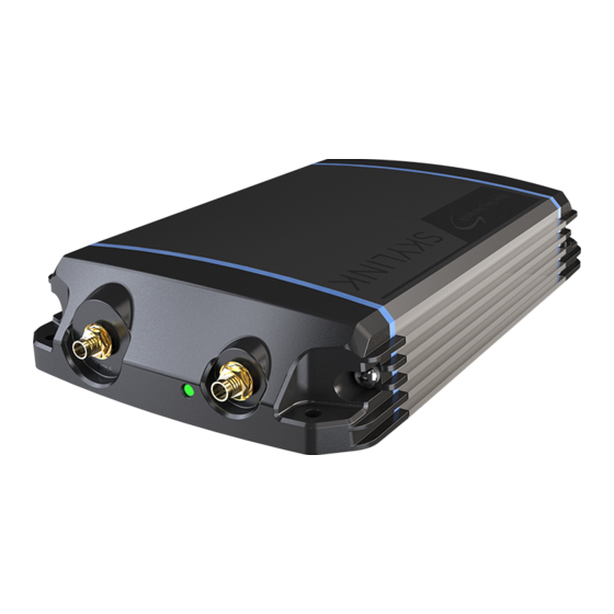
Page 8: Top Panel Description
Blue Steady = Device is Ready • Red Blink = Iridium Firmware Upgrade • Blue Blink = SkyLink Firmware Upgrade 3. Cellular Antenna Connector • Closest connector to power LED indicator Page 8 of 29 © 2021 Blue Sky Network, All Rights Reserved... -
Page 9: Bottom Panel Description
NOTE: See for information regarding cable construction requirements. SkyLink DC Pigtail Harness This is the cable you receive if you request the currently labeled ‘SL100-IS, SkyLink 10’ Power Interface Cable with QuickPosition (QPos).’ Below are the specs. OPERATING PARAMETERS Electrical •... -
Page 10: Back Panel Description
Product serial number • Iridium IMEI • WiFi SSID and password • Required certification notifications • Power and mechanical specifications • Scannable QR code to access device WiFi Page 10 of 29 © 2021 Blue Sky Network, All Rights Reserved... -
Page 11: Mounting & Installation
SkyLink Installation Guide v1.10 MOUNTING & INSTALLATION Mounting The SkyLink device should be securely fastened to a rigid object to ensure optimal functionality. There are three recommended methods for securing the terminal: MOUNTING THE UNIT All four corners of the device contain holes that can be used to affix the unit via straps, ties, or bolts. -
Page 12: Mounting With Skylink Mounting Bracket
SkyLink Installation Guide v1.10 MOUNTING WITH SKYLINK MOUNTING BRACKET A universal mounting bracket with vibration dampening is included with your purchase of SkyLink, allowing for the unit to be securely anchored to a fixed structure such as a wall. An optional pole mount can also be purchased with the kit. -
Page 13: Other Installation Equipment
SkyLink Installation Guide v1.10 Other Installation Equipment In addition to the equipment described above, the following may be useful to have during installation: • Screwdriver & Socket Set Page 13 of 29 © 2021 Blue Sky Network, All Rights Reserved... -
Page 14: Location Requirements
Any operation. Any asset. Anywhere. SkyLink Installation Guide v1.10 Location Requirements The following must be observed when installing the SkyLink terminal and antennas: ANTENNAS NOTE: Certus-certified antennas for SkyLink are required. See the Antenna Requirements section for a list of approved antennas. -
Page 15: Location Suggestions
SkyLink Installation Guide v1.10 Location Suggestions For the following diagrams, location suggestions for SkyLink are in and for the antenna in BLUE. Each section also includes a brief description of the location suggestions. VEHICLE SkyLink Antenna • • Under driver or... -
Page 16: Ship
A clear view of +/-2⁰ below the horizontal plan is needed to provide full functionality under extreme pitch conditions. Page 16 of 29 © 2021 Blue Sky Network, All Rights Reserved... -
Page 17: Building
MARUWA antenna while and/or data speed issues. it is directly connected to the terminal. Page 17 of 29 © 2021 Blue Sky Network, All Rights Reserved... -
Page 18: Aircraft/Uav
Any operation. Any asset. Anywhere. SkyLink Installation Guide v1.10 AIRCRAFT/UAV NOTE: For more detailed information, please see the SkyLink 7100 Installation Guide. SkyLink Antenna • • Installed internally On fuselage Page 18 of 29 © 2021 Blue Sky Network, All Rights Reserved... -
Page 19: Equipment Setup
EQUIPMENT SETUP Step 1 – Install Cellular & Iridium SIM Cards NOTE: If you purchased your SkyLink device through Blue Sky Network, the unit will come with cellular and Iridium SIM cards already installed. To install your cellular and Iridium SIM cards: 1. -
Page 20: Step 2 - Attach Cellular & Iridium Antennas
SkyLink Installation Guide v1.10 Step 2 – Attach Cellular & Iridium Antennas CELLULAR ANTENNA The SkyLink device uses an LTE extender antenna that connects directly to the cellular antenna connector located on the top panel of the unit. Page 20 of 29... -
Page 21: Iridium Antennas
SkyLink Installation Guide v1.10 IRIDIUM ANTENNAS The SkyLink device utilizes Iridium antennas with both direct and non-direct connection to the unit. Use the Iridium antenna connector located on the top panel (“IRI” will be etched into the connector’s recess). NOTE: All antennas should be positioned in a location where they have an unobstructed, full view of the sky. - Page 22 • Max acceptable cable loss: 1.0dB (i.e., <5’ LMR240 cable) Connect the BSN-provided cable to the respective antenna, then attach the other end to the Iridium antenna connector. Page 22 of 29 © 2021 Blue Sky Network, All Rights Reserved...
-
Page 23: Antenna Requirements
SkyLink Installation Guide v1.10 ANTENNA REQUIREMENTS Listed below are the Iridium antenna requirements for the SkyLink device. Please contact us if you have any questions or need an antenna. MARUWA Antenna (MHL-1621C) High-Profile Maxtena (M1621HCT-HP) • Passive antenna • Passive antenna •... -
Page 24: Step 3 - Attach Power
Please see the question, “My kit came with a POE power source. What is it and how do I use it?” in the FAQ section of the SkyLink User Guide if you need further assistance. -
Page 25: Step 4 - Attach Adapters
NOTE: An FXS or FXO adapter needs to be plugged into the USB adapter in order to use a POTS phone or phone system. Use an FXS adapter to connect a POTS phone to SkyLink and an FXO adapter to connect a phone system. -
Page 26: Appendix A - Troubleshooting
LED indicator. It has “IRI” etched into the connector recess. 2) Ensure the SkyLink LED illuminates. If the power LED indicator is stuck on red, this is an indication of a hardware issue. Remove the power cable from the power port and wait approximately 60 seconds, until the power LED indicator fades from green to dark. -
Page 27: Appendix B - Cable Diagrams
Cable diagrams can be created for specific installations upon request. Please do not hesitate to contact us if you have a need for more extensive diagrams. Blue Sky Network can make cables too! If you would like, we can produce cables based on your installation needs. Please contact us for more detail. - Page 28 Any operation. Any asset. Anywhere. SkyLink Installation Guide v1.10 *Placeholder for diagrams Page 28 of 29 © 2021 Blue Sky Network, All Rights Reserved...
-
Page 29: Support
SkyLink Installation Guide v1.10 SUPPORT Blue Sky Network is committed to providing the highest level of service and support. If you have any questions or concerns, please feel free to contact us by email or phone; contact information is available at the bottom of this page.
Need help?
Do you have a question about the SKYLINK and is the answer not in the manual?
Questions and answers