Table of Contents
Advertisement
Quick Links
Advertisement
Table of Contents

Related Manuals for EMX Industries UVX-300G-C


Summary of Contents for EMX Industries UVX-300G-C
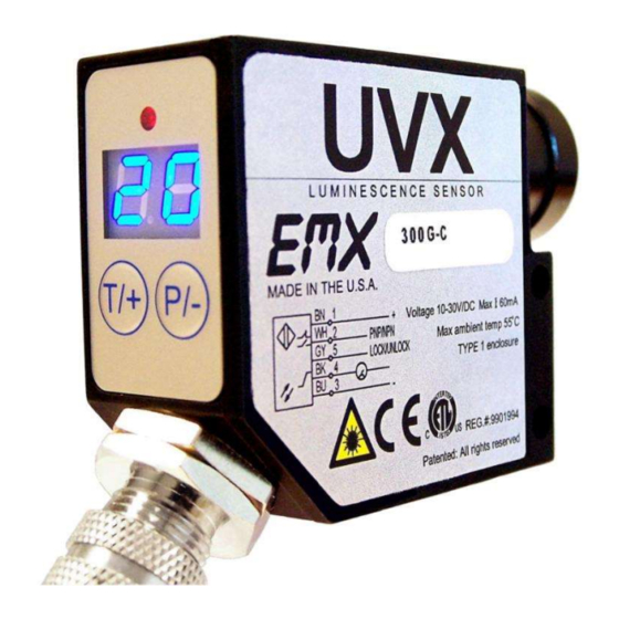
- Page 1 UVX-300G-C INCLUDES UVX-300G-FGC Luminescence sensor Operating Instructions...
-
Page 2: Cautions And Warnings
Si le visionnement de la lumière UV est nécessaire, employez svp les verres filtrés UV pour éviter des dommages d'oeil par la lumière UV. Évitez l'exposition directe d'oeil à la lumière UV. Subsistance hors de l'extension des enfants. CERTIFICATIONS: CE, CSA, UL UVX-300G-C Operating Instructions Document no. 10010404 Rev 1.6... -
Page 3: Product Overview
Operating Current 60 mA Short Circuit Protection Yes (Outputs) Overload / Reverse Polarity Protection Yes (Supply Voltage) Operating temperature -20°C…55°C Storage temperature -20°C…70°C Housing Metal alloy Mechanical protection IP65 NOT FOR PRESURE WASHDOWN UVX-300G-C Operating Instructions Document no. 10010404 Rev 1.6... -
Page 4: Operation
T/+ and P/- for 3 seconds until LL is not displayed. While the sensor is locked, pressing either P/- or T/+ will result in LL (Local Lock) indication on the display. Programmable Parameters UVX-300G-C Operating Instructions Document no. 10010404 Rev 1.6... - Page 5 00. Press and hold the T/+ key to null the sensor. The display will flash the value that is being subtracted. To set the sensor back to a true zero, aim the sensor away from any target and repeat the null process. UVX-300G-C Operating Instructions Document no. 10010404 Rev 1.6...
- Page 6 PLC. CAUTION: The discrete output must not be connected to outputs from other sensors (i.e. outputs from multiple sensors must not be connected in parallel). Parallel connections may damage sensor output circuitry. UVX-300G-C Operating Instructions Document no. 10010404 Rev 1.6...
-
Page 7: Display Indicators
None illuminated LED low intensity One illuminated LED medium intensity Two illuminated LED high intensity M12 connector pin assignments M12 Connector Wire Color Description Pin 1 Brown Power 10 to 24VDC UVX-300G-C Operating Instructions Document no. 10010404 Rev 1.6... -
Page 8: Ordering Information
The focal lens is mounted by screwing the collar into the sensors standard lens collar. An anti—vibration material is present on the focal lens threads. If necessary, use soft cloth with pliers to remove. Dimensional Details UVX-300G-C Operating Instructions Document no. 10010404 Rev 1.6... - Page 9 Sensor I/O Connections UVX-300G-C Operating Instructions Document no. 10010404 Rev 1.6...
-
Page 10: Warranty
Warranty UVX-300G-C Operating Instructions Document no. 10010404 Rev 1.6... - Page 11 UVX-300G-C Operating Instructions Document no. 10010404 Rev 1.6...
- Page 12 4564 Johnston Parkway Cleveland, Ohio 44128 United States of America http://www.emxinc.com Technical Support: (216) 518-9889 E-mail: technical@emxinc.com Sales: (216) 518-9888 Fax (216) 518-9884 E-mail salessupport@emxinc.com Demonstration target for UVX 300-G Revision 1.6 8.8.21 UVX-300G-C Operating Instructions Document no. 10010404 Rev 1.6...
Need help?
Do you have a question about the UVX-300G-C and is the answer not in the manual?
Questions and answers