Table of Contents
Advertisement
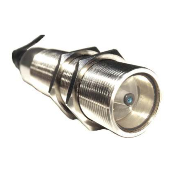
Quick Links
Advertisement
Table of Contents

Related Manuals for EMX Industries ColorMax CM1000-1-4


Summary of Contents for EMX Industries ColorMax CM1000-1-4
- Page 1 Operating Instructions...
-
Page 2: Table Of Contents
TABLE OF CONTENTS CAUTIONS AND WARNINGS .................... 3 PRODUCT OVERVIEW....................3 SPECIFICATIONS ......................4 3.1. DISCRETE OUTPUT CHART FOR HEX MODELS ..............5 3.2. RGB ANALOG OUTPUTS .................... 5 3.3. COLORMAX FLEX MODELS ..................5 QUICKSTART......................6 SOFTWARE INSTALLATION .................... 7 SENSOR INSTALLATION .................... -
Page 3: Cautions And Warnings
Windows is a trademark of Microsoft Corporation ColorMax is a trademark of EMX Industries, Inc. ColorMax Operating Instructions Document No. 10030104... -
Page 4: Specifications
3. SPECIFICATIONS ColorMax SPECIFICATIONS White LED 400…700 nm Light source • • • • • • • • • • • • • • • • • • • • • • • • • • • • • • • • • • • • • • • • • • • • • • • • • • • • • • • • • • • • • • • • 4 mm Spot dia. -
Page 5: Discrete Output Chart For Hex Models
3.1. DISCRETE OUTPUT CHART FOR HEX MODELS CM1000-15 HEX4, CM1000-15 HEX8, CM1000-15 HEX25 DISCRETE OUTPUTS CHANNEL MATCH not used not used not used None not used not used not used Channel 1 not used not used not used Channel 2 not used not used not used... -
Page 6: Quickstart
Second, a data-logging feature is provided in the Application program allowing readings to be saved to a file for further analysis. Set-up and control of the data logging is performed under control of the Applications program (refer to section 9.1.2 Triggering and section 11 Sensor Data Transmission and Data Logging for further information). -
Page 7: Software Installation
Repeat this step by selecting the next Color Recognition channel, positioning the next target, then teaching the channel. 10. After teaching several channels, note the status of the LEDs on the Color I/O box and the indicators in the Recognized Colors frame in the Application program. Place target 1 into position in front of the sensor. -
Page 8: Connections
The RS 232 connection consists of a modular jack (a phone style plug), cable and 9-pin adapter. To connect the RS232 port, plug one end of the interface cable (with the RJ11 phone plugs) into the RS232 jack on the Color I/O and the other end into the 9-pin adapter. - Page 9 NOTE: On RGB models the black, yellow and gray wires connect to the I/O box terminals 10, 11 and 12 respectively. ColorMax Operating Instructions Document No. 10030104...
-
Page 10: Colormax Application Program
9. COLORMAX APPLICATION PROGRAM ColorMax Application Program provides a comprehensive approach to sensor set-up, file management and real- time sample analysis. The ColorMax Application Program provides a familiar Windows environment creating an intuitive user interface. All essential sensor information is presented in one window including, sensor settings, color recognition channel data and real-time display of color data. -
Page 11: Minimum Output Duration (Ms)
separate proximity sensor detects the presence of a sample and signals the sensor to check with the pre-programmed color recognition channels to determine whether there is a match. Alternatively, the sensor can be operated in the Free Run mode, and a separate proximity sensor can be connected to the data acquisition system or PLC indicating a sample is present and the discrete output is valid. -
Page 12: Communication Status
2. To determine the COM port assignment select the Windows™ Control Panel, System Properties. Select the Hardware tab and the Device Manager. Scroll down the device list to Ports (COM & LPT) and expand the list (+). The Color Sensor port assignment will be shown in the list. 3. -
Page 13: Color
9.3.4. COLOR % The RED, GREEN and BLUE Color (%) boxes show the values programmed into the selected channel. If the channel was programmed in the Color & Luminosity mode, these values represent a percent of full scale for each color component. If the channel was programmed in the Color only mode, these values represent the proportion of each color component in the composite signal (i.e. -
Page 14: Teach Colormax Channel
9.3.10. TEACH COLORMAX CHANNEL The Teach ColorMax Channel button initiates a sequence of sampling the input signals resulting in current values, tolerances and other specific channel parameters to be stored in the sensor. Executing the teach function applies only to the selected channel. While the teach function is performed by the sensor for several seconds all user selections in the application program are temporarily disabled. -
Page 15: Display Mode
and blue components. The Current Reading display is useful in initial set-up for determining optimum sensor-to-target distance, sensor-target angle and relative reflected intensity of multiple samples prior to beginning the teaching sequence. 9.4.1. DISPLAY MODE The Display Mode allows the user to select Color & Luminosity, resulting in a bar graph display of current reading, or Color only, resulting in a pie chart representation of current reading. -
Page 16: Sensor Data Transmission And Data Logging
7. Observe the signal level for each color component. Generally, best results are achieved by setting the sensor-to-target distance to obtain a signal level near 80% as indicated in the Current Reading frame in the Application window. Check the remaining samples to verify that the signal levels for each of the color components are below the full scale, 100%, level. -
Page 17: Using Data Logging In The Application Program
NOTE: When using the Application program, always disable the external triggering by placing it high (V+). ASCII data may be acquired using a terminal program on a PC. The COM port settings are 9600 BAUD, 7 data bits, even parity, 1 stop bit, and flow control is set to none. The maximum data rate is approximately 40 measurements per second. -
Page 18: Input/Output Signal Descriptions
4. Select OPTIONS, DATA LOGGING, START to begin logging data to a file. A message at the bottom of the Application screen indicates logging is in process. 5. Select OPTIONS, DATA LOGGING, STOP to terminate logging. The log file may be opened in a text editor or spreadsheet for further analysis. A sample log file is shown below: 9:10:58 39.6... -
Page 19: Application Notes
13. APPLICATION NOTES SENSOR RANGE Range is dependent on target color(s). Darker colors absorb more light and consequently return less signal than lighter colors, therefore, may require shorter sensor-to-target distance. SPOT SIZE In most applications, the target color should be contained within the illuminated area. For example, a target that is only partially in the illuminated area will cause the sensor to include color signal from the surrounding area, which may affect the ability to reliably recognize the target color. -
Page 20: Colormax Spot Size Chart
ColorMax SPOT SIZE CHART ColorMax spot size 25mm Sensor-to-target distance (mm) ORDERING INFORMATION CM1000-1-4 Color sensor, one discrete output, 4mm spot CM1000-4-4 Color sensor, four discrete outputs, 4mm spot CM1000-7-4 Color sensor, seven discrete outputs, 4mm spot CM1000-15HEX4 Color sensor, fifteen encoded discrete outputs, 4mm spot CM1000-4-RGB4 Color sensor, four discrete outputs, RGB outputs, 4mm spot CM1000-FLEX4... -
Page 21: Accessories
ACCESSORIES ColorMax ACCESSORIES CM1000-KIT2 includes the following parts: Interface cable assembly, 12 conductor M12-12-5 Jam nut, M30 x 1.5 mm hex 80-M30X1.5HEX ColorMax I/O board, terminals, status LEDs CM1000-I/O2 Mounting bracket, stainless steel M30-SS-BRKT Power supply, 12 V @ 300 mA 240-56857 Windows™... -
Page 22: Certifications: Ce, Csa, Ul
CERTIFICATIONS: CE, CSA, UL Registration #9901994 ColorMax CASE DIMENSIONAL OUTLINE Thread M30 x 1.5 10mm 30mm 108mm ColorMax Operating Instructions Document No. 10030104... - Page 23 ColorMax Operating Instructions Document No. 10030104...
- Page 24 BLANK PAGE ColorMax Operating Instructions Document No. 10030104...
- Page 25 4564 Johnston Parkway Cleveland, Ohio 44128 United States of America http://www.emxinc.com E-mail sensors1@emxinc.com Telephone (216) 518-9888 Fax (216) 518-9884 Revision 1.7 5.11.11 ColorMax Operating Instructions Document No. 10030104...
Need help?
Do you have a question about the ColorMax CM1000-1-4 and is the answer not in the manual?
Questions and answers