
Related Manuals for HOLLAND HEATER HHO 8L


Summary of Contents for HOLLAND HEATER HHO 8L
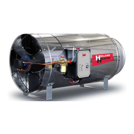
- Page 1 Installation and User manual HHO 8-10-12L Oil fired air heater Introduction Holland heats the world...
- Page 2 Take good care of this manual and store it near the heater! The oil used as fuel must be purified, never use polluted fuels or certain Bio fuels, This will harm the heater directly! Copyright 2012 by Holland Heater Holland Heater De Lier B.V. Leehove 2...
-
Page 3: Table Of Contents
Table of Contents General information ........................4 Disclaimer .............................. 5 Product description ..........................5 Used symbols ............................6 Identification of the air heater ......................6 Ordering spare parts ..........................6 Precautions and warnings ...................... 7 Technical specifications ......................9 General product specifications ......................9 Main sections and components ....................... - Page 4 V16 HHO SERIES...
-
Page 5: General Information
The content of this manual could also be changed without preceding notification. This manual is valid for the standard version of the oil fired air heater. Holland Heater can not be held responsible for possible damage or injury resulting from the deviant specifications of the standard version delivered device. -
Page 6: Used Symbols
Used symbols Warning of a general danger Warning of dangerous voltage Identification of the air heater An identification plate can be found on the delivered air heater. It contains information about the producer, model, serial number etc. The image on the right is an example of what the identification plate could look like. -
Page 7: Precautions And Warnings
Precautions and warnings General • Never use polluted fuels or certain Bio fuels, This will harm the heater directly! • Regular proper cleaning of the heater avoid uncontrolled fire! • Before using the heater, read the safety instructions and make sure that the heater, fuel lines, oil tank, electrical supply and room thermostat are connected as described. - Page 8 Safety • Any work extending beyond the scope of equipment maintenance must be performed by a qualified technician only. • Never remove the safety grill or inspection hatch while the heater is active or could be activated. • Do not press the lockout-reset button more than once in case of a failure. If the heater keeps locking out, isolate it from the mains electrical supply by removing the mains plug from the socket and contact a qualified technician.
-
Page 9: Technical Specifications
Technical specifications General product specifications Oil-Fired Warm Air Heater Model HHO - Output kcal/h 69000 86000 103000 27300 341200 409450 Fuel consumption Kg/h Air output 7700 7700 7700 cfm. 4543 4543 4543 Motor speed 1400 1400 1400 Electric Tension 50-60Hz V Electric current 230V-50Hz A Power... -
Page 10: Main Sections And Components
Main sections and components 2.2.1 The 8 and 10L versions Pos. Name Item nr. Pos. Name Item nr. Oil pump (see 2.4) Grill Engine bracket LeMac Fan Engine 490031 Oventrop Oilfilter (see 2.4) Heater support bracket Fan 20” 28º Edge profile 490035 Inspection hatch Mounting plate for oilfilter... -
Page 11: Differences Between 8-10L Version And 12L Version Of The Heater
2.2.2 Differences between 8-10L version and 12L version of the heater 8-10L The differences between a 8L heater or a 10L heater is just a different fuel nozzle. However the differences between a 10L and a 12L heater are somewhat more elaborate. The main difference is that the 12L heater has a bigger burnerchamber (6) not only is it longer the diameter is also larger. - Page 12 2.3 Electrical components Pos. Name Item nr. Pos. Name Item nr. Fault indication lamp 510146 Max.thermostat 510173 Ignition transformer 100046 Max.thermostat bracket Mountingboard components Main operating switch 510140 Circuit breaker 510069 Burner controller 490032 Timer 490056 Reset button 510135 Relay 510125 Terminal Strip V16 HHO SERIES...
- Page 13 Input from fuel tank Output for air bleeding/ return Oil filter Oventrop 490044 The correct pump pressures for the various models of heater are shown in the table below Type HHO 8L HHO 10L HHO 12L Kerosene 9 bar 9 bar...
-
Page 14: Burner Set
Burner set The burner set is a vital part of the heater. Its function is to light the oil coming out of the nozzle, and it must be capable of doing so under adverse conditions. It is therefore very important that it is properly adjusted. -
Page 15: Oil Atomising Nozzle
Discharge Flow Nozzle Item no. model nozzle (US-gal/h) ltr/h model DANFOSS 2,00 HHO 8L 60 S 2,25 490041 HHO 10L 60 S 2,75 490082 HHO 12L 60 S The burner disk The burner disk is attached to the nozzle block. The burner disk ensures that the fuel and air are thoroughly mixed and trained to form a spiral jet. -
Page 16: Air Inlet Chamber
Air inlet chamber The air inlet chamber is the square housing mounted to the burner chamber. The burner set is attached onto the air inlet chamber. The air inlet chamber has four air inlets that provide air (oxygen) that is needed for the combustion process. -
Page 17: Installation
Installation General Mind the following precautions before installing the heater: Mounting • The heater must be properly secured using the suspension eyes or (if it is being fixed down) using the tunnel brackets on its bottom. Secure the heater using chain or steel cable of at least 4 mm in diameter. - Page 18 Safety • Never use polluted fuels or certain Bio fuels, This will harm the heater directly! • Never remove the grill or service hatch when the heater is or might start running. • Never use the heater when parts are removed. •...
-
Page 19: Connecting The Oil Supply
Connecting the oil supply Note the distance of the heater to feeding and drinking equipment and to plants in glasshouses concerning dehydration. Legend of the images in the next four paragraphs: A. Non-return valve D. Reduction regulator B. Filter E. Vacuum valve C. -
Page 20: Use Of An Extra Oil Pump
3.2.3 Use of an extra oil pump Mind the pump pressure; use a reduction regulator (D). The pressure on the filter may not exceed 0,5 bar. If necessary, use aluminum or brass filter jars or oil conduits that can sustain higher pressure and clamp them well on the nipples! Always use a filter (B) when the oil or... -
Page 21: Mobile Heater With Tank
3.2.5 Mobile Heater with tank The mobile HHO oil with tank takes his oil directly out of the tank, on the tank is an oil filter mounted. (B) is oil filter. Warning! Before you connect the heater to the mains and start using the heater you have to fill up the tank! Use only diesel of a good quality! To run the heater without oil in the tank... - Page 22 V16 HHO SERIES...
-
Page 23: Oil Lines
Oil lines Always use oil-resistant lines with the correct line clips. The following features of the oil supply system must be compatible with one another: • The total length of oil line used (i.e. fuel line run); • The diameter of the oil line; •... -
Page 24: Electrical Connections
Electrical connections Do not connect the burner controller to the three-phase mains. Unscrew the lid from the electrical casing and open it. The connection of the thermostat, external signals and other components are described below (wiring max. 2,5 mm V16 HHO SERIES... - Page 25 Electrical scheme HHO 8 – 10 - 12L Legend: Phase 230 Volts Zero Room thermostat Heating relay Ventilation relay (Option) Switch Automatic heating Continuous heating Continuous ventilating V16 HHO SERIES...
-
Page 26: Operation
Operation First use (single pipeline system) Before using the heater, read the safety instructions and make sure that the heater, fuel lines, oil tank, electrical supply and room thermostat are connected as described. Turn the ‘on/off’ switch to position 3 (continuous ventilating). -
Page 27: First Use (Return Pipeline System)
First use (return pipeline system) Before using the heater, read the safety instructions and make sure that the heater, fuel lines, oil tank, electrical supply and room thermostat are connected as described. Check if the return line has been connected to the oil filter return. Turn the ‘on/off’... - Page 28 Open the oil filter valve and the air bleed valve. The oil now flows into the system and the oil filter will be filled. Next, the oil flows back to the internal oil system through the return line. The internal oil system of the heater is filled with oil and is bled.
-
Page 29: Regular Use
Regular use The heater ventilates for about one and a half minute after the heater has been switched off. During this one and a half minute the fan cools the burning chamber. The "ventilate" mode is particularly useful in the summer. However, make sure that there is enough oil in the tank, since the oil pump could seize if it is not being lubricated by the oil. -
Page 30: Maintenance
Maintenance General This chapter is intended for qualified technicians and not for users. Repairs should only be carried out by persons who have the training, knowledge or practical experience to ensure that the repair is done properly. Always disconnect the appliance from the mains before performing any maintenance. Important: prevent dust accumulation, clean the heater regularly •... -
Page 31: Cleaning
Cleaning Do not use water to clean the appliance! Inadequate cleaning can result in serious damage. Components that need to be thoroughly cleaned: Main shell Maximal thermostat sensor holder Motor and fan Photocell and holder Controlbox and electrical wiring Air inlet chamber Burner set Burner chamber After a fattening period of +/- 42 days or when the heater is sooner polluted by dust , the air heater... - Page 32 • If the heater is being used in a very dusty environment e.g. a broiler house, the burner set, the photocell and the photocell housing should be cleaned after every crop. To do this, remove the burnet set from the burner chamber by loosening the two wing bolts (see diagram chapter 2).
-
Page 33: Environment And Discharge
Environment and discharge Environment When ending the products lifeline, it needs to be separated from other waste. The user is obligated to take the product to a location to hand in electronic devices. If this is not possible and the product needs to be replaced by a newer version, send the product back to the manufacturer. -
Page 34: Burner Controller Response To Failures
Failures Burner controller response to failures The table below illustrates the response of the burner controller to various types of malfunctions. After the appliance has frozen, the red signal lamp will light up. When the power is restored following a power failure, the appliance will still be frozen. -
Page 35: Burner Relay Malfunction Indicator
During normal operation, the various operating statuses are indicated in the form of colour codes, as shown in the colour coding table below. During start-up, the status is indicated in the table on the next page. Colour coding table for the multicolour signalling lamp (LED) Status: Colour code: Colour:... -
Page 36: Malfunctions And Potential Solutions
Malfunctions and potential solutions Malfunction : The air heater does not start, even when started manually. • Possible cause: The plug is not in the wall socket. • No mains voltage. • Faulty burner relay. • Master switch is switched off. •... - Page 37 Malfunction : The air heater starts correctly, but does not ignite. Oil is however being released. The red error lamp lights up (Error code 2). • Possible cause: The ignition set is faulty. • The ignition cable makes connection, is loose or is not connected properly.
-
Page 38: Appendices
Appendices Appendix I EC Declaration of Conformity We declare that the design and model of the machine described above being placed on the market by ourselves complies with the relevant health and safety requirements of the EC Directive. The heater described in this manual meets the requirements of the following EEC directives: •... - Page 39 V16 HHO SERIES...
- Page 40 Copyright 2014 by Holland Heater Holland Heater De Lier B.V. Leehove 2 2678MC De Lier The Netherlands Tel: +31 (0)174 51 67 41 Fax: +31 (0)174 51 80 21 E-mail: info@hollandheater.nl Website: www.hollandheater.nl V16 HHO SERIES...
Need help?
Do you have a question about the HHO 8L and is the answer not in the manual?
Questions and answers