
Related Manuals for HOLLAND HEATER HHB Series


Summary of Contents for HOLLAND HEATER HHB Series
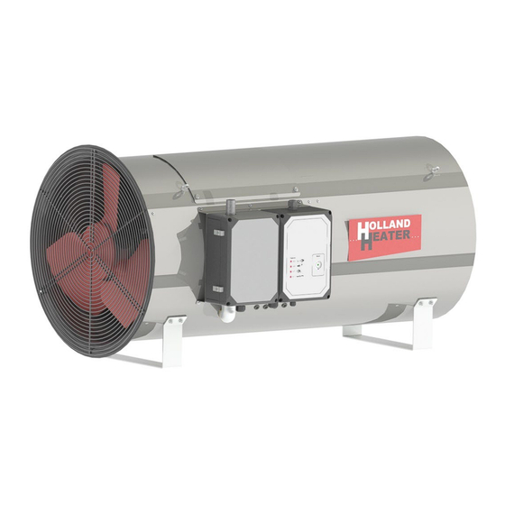
- Page 1 Installation and user manual HHB SERIES Direct gas fired air heater HOLLAND HEATER HEATS THE WORLD HHB-SERIES v1.0...
- Page 2 HHB-SERIES v1.0 General...
- Page 3 This is the original manual of the HHB. If you cannot find the information you need, or if you need other information, please contact your supplier. Holland Heater Keersopstraat 55 3044 EX Rotterdam The Netherlands Tel: +31 (0)174 51 67 41 Fax: +31 (0)174 51 80 21 E-mail: info@hollandheater.n Website: www.hollandheater.nl Copyright 2023 by Holland Heater General HHB-SERIES v1.0...
-
Page 4: Table Of Contents
GENERAL MANUAL GENERAL SECTION ....................6 General information ......................6 Foreword ......................... 6 Liability waiver ......................6 Product description ....................6 Basic information ..................... 7 Pictograms and safety symbols ................7 Service and technical support .................. 7 Warranty provisions ....................7 Identification of the device .................. - Page 5 Troubleshooting....................23 10.1 General ........................23 10.2 Burner relay response to malfunctions ..............23 10.3 Burner relay status indicator ...................24 10.4 Burner relay malfunction indicator ................25 10.5 Malfunctions and potential solutions ...............26 10.6 Technical support ....................28 FOR END USERS ....................29 Operation .......................29 12.1 General functioning ....................29 12.2 Control ........................30...
-
Page 6: General Section
Holland Heater B.V. shall not be held liable for any damages or injuries arising because of failure to comply with the instructions provided within this manual. -
Page 7: Basic Information
The sales and warranty provisions applicable to the air heater, as per the Metal union conditions, form part of the terms and conditions of delivery. Holland Heater is registered with the Chamber of Commerce under number 27226471. General HHB-SERIES v1.0... -
Page 8: Identification Of The Device
Identification of the device The identification plate of your air heater is fixed to the appliance. This lists the correct information for the air heater supplied. The figure below shows an example of a possible identification plate. Fig. 2.8-1 Example of identification plate Ordering spare parts It is essential that you state the following information when ordering parts: •... -
Page 9: User Manual
2.2 User manual • Any person working on or with the air heater must be aware of the content of this user manual and must follow the instructions herein precisely. The management must use this manual to train personnel and must observe all instructions and directions. -
Page 10: Safety Regulations And Hazard Warnings
2.6 Safety regulations and hazard warnings General 2.6.1 • Regular maintenance of the appliance prevents malfunctioning. • Read this manual before first use. The gas supply, electrical supply and thermostat must be connected as described. • Any illegal change to the appliance rules out manufacturer’s liability for any resulting damage. •... -
Page 11: Technical Specifications
Technical specifications 3.1 Overview HHB-040 HHB-070 HHB-100 HHB-120 Nominal load on upper value Nominal load on upper value 136136 238910 371923 406044 Gas consumption natural gas (H-Gas @ 15°C) m 3.77 9.45 11.4 Gas consumption natural gas (L-Gas @ 15°C 4.47 7.76 11.08... -
Page 12: Dimensions
3.2 Dimensions HHB-40 Sideview Back view HHB-70 Sideview Back view HHB-100/120 Sideview Back view Figure 4.1 -Dimensions Safety devices 4.1 General • All safety devices must be fitted correctly and may only be removed by trained and authorised service technicians for the purpose of maintenance and repair works. The air heater must never be used when the safety devices are not complete or are not fitted or if the •... -
Page 13: Modifications
4.2 Modifications It is prohibited to modify the air heater in any way. • • The specifications outlined in this document must not be changed. 4.3 Installation The installation, maintenance and repair of the air heater and any adjustments must only be carried out •... -
Page 14: For Authorized Persons
FOR AUTHORIZED PERSONS The following chapters refer to authorized persons who have sufficient training and knowledge to be able to carry out operations on the appliance. Installation Gas connection Pursuant to NEN 1078, and NEN 8078, the connection of the gas supply must be carried out by qualified personnel. -
Page 15: Connecting Thermostat
Connect the electric mains through a reliably earthed and watertight wall socket, which is provided with power via a load-protection circuit-breaker with a guaranteed value of 16 Amp. A 3-core cable must be used for the single-phase connection, which must be connected to the terminals marked L, N and PE (earth) in the air heater control box. -
Page 16: Connecting External Controls
Connecting external controls 6.2.2 Heating Ventilation External heating control (thermostat or climate computer) computer) External ventilation control (thermostat or climate computer) External power 24 Vac Optional 24Vdc or 230Vacco 7.2-3 Connecting external controls External control. Supplying several heaters 6.2.3 External heating control (thermostat or climate computer) computer) -
Page 17: General Points
6.3 General points The air heater must be installed horizontally. Ensure the air heater is protected from rain, leaks, etc. Figure 7.3-1 shows how the air heater should be installed and positioned. Under no circumstances must hoses and/or ducts be mounted on the sides where the inlet and outlet are located. -
Page 18: Instructions Prior To First Use
6.4 Instructions prior to first use The air heater may only be used by authorised persons, as specified previously in sections 6.1 and 6.2. Once the air heater is connected according to the directions specified in sections 4 and 5, it is essential that the following points are checked prior to first using the appliance: The gas connections and ventilation of the gas pipe, see section 6.1. -
Page 19: Gas Block
6.5 Gas block Solenoid valve EV1 50Hz 31.1 Measure point – Pre gas pressure 31.2 Measure point – Burner pressure 31.3 Setting point - Burner pressure. Solenoid valve EV2 50Hz Gas block Figure 7.2-1: 50Hz Solenoid valve EV1 60Hz 31.1 Measure point – Pre gas pressure 31.2 Measure point –... -
Page 20: Maintenance
Maintenance Always remove the plug from the wall socket and shut off the gas supply when carrying out work on the appliance. Note! The air heater is phase sensitive. For the air heater to function, it is essential that the plug is reinserted into the wall socket in the correct manner. -
Page 21: Ventilators
When using a high-pressure hose, ensure that parts 3.1 and 5 do not come into direct contact with the jet from the high-pressure hose. These parts are highly sensitive and must be handled with care. After hosing off the appliance with water, the air heater must be set to ventilate for at least 15 minutes (see fig. -
Page 22: Environment
Assembled Disassembled Fig. 9.1-1 (Dis)assembling of the injector. Pos. Name: Item no. Pos. Name: Item no. Flexible gas pipe 020044 Ignition electrode 020031 Swivel nut 520109 Parker Reducer 020021 Gasket ring 520070 Nozzle See fig. 9.1-2 M5 nut + ring The differences between the natural gas and propane/butane nozzle are shown in the figure 9.1-2 below. -
Page 23: Troubleshooting
10 Troubleshooting 10.1 General When resolving malfunctions, it is recommended to check the following first: • The appliance is connected to the correct voltage 240 V +/- 10%. Problems can occur if there is no connection to the mains voltage supply or if the supply voltage is too low. The appliance is supplied with the correct quantity of gas. -
Page 24: Burner Relay Status Indicator
10.3 Burner relay status indicator During normal operation, the various operating statuses are indicated in the form of colour codes, as shown in the colour coding table below. During start-up, the status is indicated as shown in the following table 10.3-1 Tabel 10.3-1 Burner relay status indicator Colour coding table for the multicolour signalling lamp (LED) Status:... -
Page 25: Burner Relay Malfunction Indicator
10.4 Burner relay malfunction indicator After the appliance has frozen, the red error signalling lamp on the top of the box will remain lit continuously. In this situation, the visual diagnosis of the cause of the malfunction according to the error code table can be activated by holding down the reset button for 3 seconds. -
Page 26: Malfunctions And Potential Solutions
10.5 Malfunctions and potential solutions Malfunction : The air heater does not start, even when started manually. Possible cause: The plug is not in the wall socket. • No mains voltage. • • Faulty burner relay. Master switch is switched off. •... - Page 27 Malfunction: The air heater starts correctly but does not ignite. Gas is however being released. The red error lamp lights up (Error code 2). The ignition set is faulty. • Possible cause: The ignition cable has poor connection, is loose or is not •...
-
Page 28: Technical Support
Malfunction : The appliance starts up but does not ignite and there is no gas. The fan rotates however (Error code 5 or 10). Possible cause: • Fan rotates too slowly and does not turn on the vane. Vane is not functioning correctly. •... -
Page 29: For End Users
12 Operation 12.1 General functioning The Holland Heater HHB air heater is a direct gas fired air heater which means that the exhaust flues resulted from burning gas are supplied directly to the air being heated. This has the important advantage that the efficiency of the heating is maximum (all the heat is used, so the efficiency is 100%). -
Page 30: Control
The integrated ventilator ensures that air flows through the vanes of the twisted disk on the inlet side of the burner chamber and the cone into the burner chamber. Most of the air flows between the burner chamber and the outer casing and provides maximum air-throw at an average low air temperature. - Page 31 Fig.12.2-2 Overview of Gas valve and Control panel Description: Item no. Description: Item no. Flexible Gas Pipe 20044 Circuit breaker 510069 Gas valve SIT 520154 Relay K1&K2 24VAC 530131 Terminal ¾” Relay K1&K2 24VDC 510291 Condensator - 8 µF 510058 Relay K1&K2 230VAC 510118 Ignition transformer ZT870...
-
Page 32: Annexes
13 Annexes Annex A – Gas pressures for different types of gas The burner pressure is dependent on the calorific value and the density of the gas. To establish a direct connection to the required burner pressure, the so-called Wobbe index has been introduced. -
Page 33: Annex B: - Spare Parts & Accessories
13.1 Annex B: - Spare Parts & Accessories Item Number Description Image 520058 Gas Valve - ¾" 520250 Gas Valve - ½" 520089 Gas Hose - Gas ½" 520029 Regulator - ¾" 520251 Regulator - LP/Propane Gas ½" 520032 Filter - Natural Gas ¾" 510173 Max. - Page 34 Item Number Description Image 490022 Reducer G-½" Rs-⅜" 525401 Wind Vane Switch 510047 Siemens Burner Control - LME39 020031 Ignition Electrode 510109 Ignition Transformer 510291 DC Relay-24V 2W 8 Amp 530155 AC Relays-230V 1W 16 Amp HHB-series v1.0 Annexes...
- Page 35 Item Number Description Image 510069 Circuit Breaker 10 Amp 020099 Capacitor 10μF 520154 Gas Valve SIT 520171 Cable - Gas Valve Nova 822 510106 Cable - Transformer ZT870 510140 Selector Switch 520129 Nozzle HHB-70 NG 520130 Nozzle HHB-70 LP/LPG 510270 Fan 70kW Annexes HHB-SERIES v1.0...
- Page 36 Item Number Description Image 520070 Grommet Ring 30x20x2 mm 020120 Grill & Inlet Ring 70kW 020121 Grill & Inlet Ring 100/120kW 500018 Ventilator + Motor 100&120kW 020044 Flexible Gas Pipe 520109 Swivel Nut 020021 Reducer 020025 Nozzle 8 x Ø2.1 mm - 40kW NG 020026 Nozzle 10 x Ø2.6 mm - 70kW NG HHB-series v1.0...
- Page 37 Annexes HHB-SERIES v1.0...
- Page 38 HHB-series v1.0 Annexes...
- Page 39 Annexes HHB-SERIES v1.0...
-
Page 40: Annex C: - Electrical Diagrams Hhb
13.2 Annex C: - Electrical diagrams HHB Diagram HHB-40, 50Hz HHB-series v1.0 Annexes... - Page 41 Terminal strip HHB-40, 50Hz Annexes HHB-SERIES v1.0...
- Page 42 Diagram HHB-70, 50Hz HHB-series v1.0 Annexes...
- Page 43 Terminal strip HHB-70, 50Hz Annexes HHB-SERIES v1.0...
- Page 44 Diagram HHB-100/120, 50Hz HHB-series v1.0 Annexes...
- Page 45 Terminal strip HHB-100/120, 50Hz Annexes HHB-SERIES v1.0...
- Page 46 Diagram HHB-40, 60Hz 2f HHB-series v1.0 Annexes...
- Page 47 Terminal strip HHB-40, 60Hz 2f Annexes HHB-SERIES v1.0...
- Page 48 Diagram HHB-70, 60Hz 2f HHB-series v1.0 Annexes...
- Page 49 Terminal strip HHB-70, 60Hz 2f Annexes HHB-SERIES v1.0...
- Page 50 Diagram HHB-100/120, 60Hz 2f HHB-series v1.0 Annexes...
- Page 51 Terminal strip HHB-100/120, 60Hz 2f Annexes HHB-SERIES v1.0...
- Page 52 Holland Heater Keersopstraat 55 3044 EX Rotterdam Netherlands Telefoon: : +31 (0)174 51 67 41 Fax: : +31 (0)174 51 80 21 E-mail: info@hollandheater.nl Website: www.hollandheater.nl Copyright 2023 by Holland Heater HHB-series v1.0 Annexes...
Need help?
Do you have a question about the HHB Series and is the answer not in the manual?
Questions and answers