Table of Contents
Advertisement
Quick Links
Advertisement
Table of Contents

Subscribe to Our Youtube Channel
Related Manuals for BK Precision 1249B


Summary of Contents for BK Precision 1249B
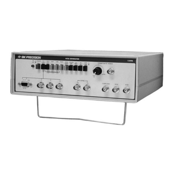
- Page 1 INSTRUCTION MANUAL Model 1249B NTSC GENERATOR...
-
Page 2: Test Instrument Safety
TEST INSTRUMENT SAFETY WARNING Normal use of test equipment exposes you to a certain amount of danger from electrical shock because testing must sometimes be performed where exposed voltage is present. An electrical shock causing 10 milliamps of current to pass through the heart will stop most human heartbeats. -
Page 3: Table Of Contents
TABLE OF CONTENTS Page Page Black Raster Pattern ............25 TEST INSTRUMENT SAFETY ......inside front cover 4.5MHz Subcarrier Use ............25 RGB Output ................25 INTRODUCTION ................4 Waveform Monitoring ............. 26 FEATURES ..................5 Simultaneous Outputs .............. 27 SPECIFICATIONS ................6 APPLICATIONS ................ -
Page 4: Introduction
INTRODUCTION it to be used to set-up and adjustment TV sets and other he B+K PRECISION Model 1249B NTSC Generator is a equipment for the best performance. This is not possible versatile, cost, precision television/video signal with lower cost gated rainbow color generators, which generator. -
Page 5: Features
FEATURES RF OUTPUT NTSC COLOR BARS Standard 75Ω output modulated by composite video at 10mV rms on channel 3, channel 4, or 45.75MHz i-f. Generates standard NTSC color bars pattern (eight bars of standard EIA colors) at NTSC prescribed luminance and chrominance levels and phase. -
Page 6: Specifications
SPECIFICATIONS PATTERNS Impedance: 75 ohms. NTSC Color Bars: White (75% or I00%. switch selectable), yellow, cyan, Stability: green, magenta, red, blue, black (7.5% set-up). Chroma is switch selectable; COLOR OFF obtains stair case from 50 ppm. color bars (stair case white level is switch selectable at 75% or 100%). - Page 7 SPECIFICATIONS (CONT.) COLOR SUBCARRIER SOUND SUBCARRIER NTSC signal: 3.579545MHz (±50Hz) (adaptable to PAL-M). 4.5MHz ±0.2% modulated by approximately 1KHz audio tone, switch selectable. MISCELLANEOUS Power Requirements: SYNC OUTPUTS 105 to 130VAC, 60Hz. 8 Watts. Composite: Operating Temperature: NTSC-M level: negative polarity sync: interlaced scan for NTSC color bars, selectable...
-
Page 8: Definitions Of Terms
DEFINITIONS OF TERMS Color Burst. A few (8 to 10) cycles of 3.58MHz color subcarrier which occur during the back porch interval. Color burst amplitude is BARS Pattern. See “NTSC Color Bars”. 40 IEEE units and phase is 180°. The color oscillator of a color television receiver is phase locked to the color burst. - Page 9 DEFINITIONS OF TERMS (CONT.) IEEE Unit. A standard 1-volt peak-to-peak composite video signal Field. One-half a television picture. One complete vertical scan is divided into 140 equal units, scaled from -40 to +100, which are of the picture containing 262.5 lines. Two fields make up a then called IEEE units.
- Page 10 DEFINITIONS OF TERMS (CONT.) Resolution. See "Horizontal Resolution" and "Vertical Vertical Blanking Interval. That portion at the beginning Resolution". of each field of composite video signal which blanks the picture while the CRT retrace returns to the top of the Saturation.
-
Page 11: The Ntsc Color Video Signal
THE NTSC COLOR VIDEO SIGNAL United States and many other countries. It was, of course, compatible with the monochrome (black and white) system that previously existed. The makeup of a composite video signal is dictated by NTSC specifications. These specifications include a 525-line interlaced scan, operating at a horizontal scan frequency of 15.734.26Hz and a vertical scan frequency of 59.94Hz. -
Page 12: Vertical Sync
THE NTSC COLOR VIDEO SIGNAL (CONT.) horizontal sync pulse at the -40 IEEE units level. An explanation interval begins with the first equalizing pulse, which consists of of IEEE units follows in the "Amplitude" paragraph. When the six pulses one half the width of horizontal sync pulses, but at horizontal sync pulse is detected in a television receiver, it twice the repetition rate. - Page 13 THE NTSC COLOR VIDEO SIGNAL (CONT.) Fig. 2A. Compo site Video Signal Showing Vertical Blanking Interval (Field 1).
- Page 14 THE NTSC COLOR VIDEO SIGNAL (CONT.) Fig. 2B. Composite Video Signal Showing Vertical Blanking Interval (Field 2)
-
Page 15: Color
THE NTSC COLOR VIDEO SIGNAL (CONT.) Hue is the element that distinguishes between colors, red, blue, green. etc. White, black and grey are not hues. The phase angle of white. Levels between +7.5 and +100 units produce various the 3.58MHz color subcarrier determines the hue. The three shadings of grey. - Page 16 THE NTSC COLOR VIDEO SIGNAL (CONT.) Fig. 3. Elements of Color Television Signal...
- Page 17 THE NTSC COLOR VIDEO SIGNAL (CONT.) luminance level (or with no luminance component) and (saturation) set forth by the NTSC. This is the test signal same chroma amplitude, which of course is not equivalent used in broadcasting studios and transmitting equipment. to the color signals being transmitted by broadcast stations.
-
Page 18: Controls And Indicators
CONTROLS AND INDICATORS 1. POWER Switch. Turns power on and off. Only LINE switch engaged: 2. RGB TTL/LOW Switch. Selects TTL or low RGB output A single vertical and horizontal line intersecting at the center of the level. When this switch is released (LOW position), a positive screen. - Page 19 CONTROLS AND INDICATORS (CONT.) approximately 1KHz) is included in the signal at the IF/RF 12. COMPOSITE VIDEO Jack. Provides a video output for signal output jack. When this switch is disengaged, no sound carrier substitution directly into the video circuits of a television receiver is included in the signal.
- Page 20 CONTROLS AND INDICATORS (CONT.) Fig. 4. Controls and Indicators...
- Page 21 CONTROLS AND INDICATORS (CONT.) 19. G Jack. Provides green output signal for use with RGB 21. RGB 9-Pin D-Type Sub-Miniature connector. Ω monitors. Output impedance is 75 and output level is Provides red, green, blue, vertical sync (Vs), and switch selectable (using the RGB TTL/LOW switch). horizontal sync (Hs) signals.
-
Page 22: Operating Instructions
OPERATING INSTRUCTIONS WARNING All outputs have a source impedance of 75Ω. Therefore, 75Ω coaxial cable RG-59/U) is recommended for To prevent electrical shock, observe the interconnecting cables. precautions listed TEST INSTRUMENT SAFETY section, located on FAMILIARIZATION the inside front cover of this manual. To familiarize yourself with the operating controls, capabilities PRECAUTION AND TIPS and operating characteristics of the NTSC Generator, we... - Page 23 OPERATING INSTRUCTIONS (CONT.) The probe may be used to inject the 45.75MHz i-f RF Output signal at the desired point. The rf output of the NTSC Generator may be applied to a television Patterns may now be selected. receiver, video tape recorder or other video equipment tunable to channel 3 or 4.
-
Page 24: Ntsc Standard Color Bar Pattern
OPERATING INSTRUCTIONS (CONT.) Release all of the pattern selection switches (the four A calibrated 1Vp-p signal level with negative sync black pushbuttons) by slightly depressing one of them. polarity is available when the COMPOSITE VIDEO Make sure that the COLOR OFF switch is disengaged. LEVEL control is fully counterclockwise to the CAL position. -
Page 25: Color Bars With 100% White
7 horizontal and 10 vertical lines or dots. color monitors are often used with computers having color graphic display capability, etc. BLACK RASTER PATTERN The Model 1249B will provide compatible test signals for most Perform the "INITIAL SET-UP" procedure. RGB monitors using standard 525 line, 15.750KHz horizontal... -
Page 26: Waveform Monitoring
Others use higher TTL level excitation mates with the RGB receptacle on the Generator, connect it. and display only fully saturated colors- The Model 1249B NTSC All necessary connections are made simultaneously. Generator provides signals for most versions. -
Page 27: Simultaneous Outputs
OPERATING INSTRUCTIONS (CONT.) The COMPOSITE VIDEO output is continuously Connect another cable from the COMP SYNC output available when the instrument is operating. The video jack to the external trigger input of the oscilloscope. component of the signal is dependent upon the selected pattern. -
Page 28: Applications
APPLICATIONS Most manufacturers specify an NTSC color bar input signal NTSC COLOR BARS in their literature. Adjustment procedures are usually based upon an NTSC color bar input, and the waveforms shown at Versatility various points on the schematic diagram are those obtained with an NTSC color bar input. -
Page 29: Staircase
APPLICATIONS (CONT.) Dots Pattern may be exam-fined throughout the VCR for proper luminance The dots pattern (DOT and 7 X 11 switches both engaged) to chroma proportions. Another problem that may be is used for static convergence, usually by converging the encountered is a difference in delay between the luminance center dot of the pattern. -
Page 30: Sync
APPLICATIONS (CONT.) SYNC feedback path and no change in servo operation was noted, the The NTSC color bars and staircase pattern include NTSC sync problem would be with the circuit that receives the feedback pulses, the same type as those produced by a broadcast station. signal. -
Page 31: Matv Applications
APPLICATIONS (CONT.) MATV APPLICATIONS Select the NTSC BARS pattern and apply to the TV set Master antenna systems for hotels, motels, apartment under test. buildings, etc. can be checked by applying the channel 3 or 4 rf output of the Generator to the input of the network (or a Set up to the oscilloscope for X-Y operation. - Page 32 APPLICATIONS (CONT.) The display shape depends upon the chroma bandpass, The vectorscope pattern can be a valuable tool for demodulator alignment, and design of the TV chassis. troubleshooting color problems, including improper The better the alignment and bandwidth, the closer the alignment and adjustment, if the normal vectorscope vector waveform will be to the ideal waveform.
- Page 33 APPLICATIONS CONT.) Fig. 7. Typical Vectorscope Display of Demodulated Color Bars Pattern Viewed on Conventional Oscilloscope.
-
Page 34: Maintenance
MAINTENANCE WARNI N G developed in the unit. Determine and correct the cause of the blown fuse, then replace only with a 1/16A, 250V slow blow fuse (B+K Precision Part No. 198-303-0-062). The fuse is The following instructions are for use by only accessible by removing the case. - Page 35 MAINTENANCE (CONT.) Fig. 8. Adjustment and Test Point Locations.
- Page 36 MAINTENANCE (CONT.) Press the CH 4/CH 3 switch on the NTSC Generator (so that it 3. Connect the Waveform Monitor and the Vectorscope to the is in the CH 4 position). COMPOSITE VIDEO jack (terminated into 75 S2). Set the Waveform Monitor response to FLAT and the sweep to 2H.
- Page 37 Waveform Monitor. Recheck Vectorscope display and speed of 1µs/div. readjust vectors if necessary. Adjust VR10 and VR11 on the 1249B for minimum Release all of the pattern selection switches (the four light ripple on the bottom edge of the sync pulse. Repeat until colored pushbuttons) by slightly depressing one of them.
-
Page 38: Service Instructions
SERVICE INFORMATION Warranty Service: Please return the product in the original packaging with proof of purchase to the address below. Clearly state in writing the performance problem and return any leads, probes, connectors and accessories that you are using with the device. Non-Warranty Service: Return the product in the original packaging to the address below. -
Page 39: Limited One-Year Warranty
LIMITED ONE-YEAR WARRANTY B&K Precision Corp. warrants to the original purchaser that its products and the component parts thereof, will be free from defects in workmanship and materials for a period of one year from date of purchase. B&K Precision Corp. will, without charge, repair or replace, at its option, defective product or component parts. Returned product must be accompanied by proof of the purchase date in the form of a sales receipt. - Page 40 For connection to any other point, an isolation transformer is needed. Capacitive coupled outputs of the Model 1249B NTSC Generator are rated at ±35 volts (DC + AC peak) maximum: this includes the IF/RF and COMPOSITE VIDEO jack. All other input and output jacks are direct coupled and are rated at ±5 volts (DC + AC peak) maximum.
- Page 41 22820 Savi Ranch Parkway Yorba Linda, CA 92887 www.bkprecision.com © 2006 B&K Precision Corp. Printed in USA PN# 480-760-9-001...
Need help?
Do you have a question about the 1249B and is the answer not in the manual?
Questions and answers