Table of Contents
Advertisement
Available languages
Available languages
Quick Links
Download this manual
See also:
Installation Manual
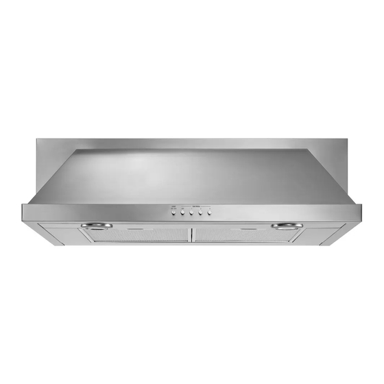
30" (76.2 CM) AND 36" (91.4 CM) RANGE HOOD
Installation Instructions and Use & Care Guide
HOTTE D'ASPIRATION DE
30" (76,2 CM) ET 36" (91,4 CM)
Instructions d'installation et Guide d'utilisation et d'entretien
Table of Contents/Table des matières............................................................................. 2
IMPORTANT: READ AND SAVE THESE INSTRUCTIONS.
FOR RESIDENTIAL USE ONLY.
IMPORTANT : LIRE ET CONSERVER CES INSTRUCTIONS.
POUR UTILISATION RÉSIDENTIELLE UNIQUEMENT.
LI3VQB/W10274302C
Advertisement
Table of Contents

Related Manuals for Amana UXT5530AAB


Summary of Contents for Amana UXT5530AAB
- Page 1 30" (76.2 CM) AND 36" (91.4 CM) RANGE HOOD Installation Instructions and Use & Care Guide HOTTE D’ASPIRATION DE 30" (76,2 CM) ET 36" (91,4 CM) Instructions d’installation et Guide d’utilisation et d’entretien Table of Contents/Table des matières... 2 IMPORTANT: READ AND SAVE THESE INSTRUCTIONS. FOR RESIDENTIAL USE ONLY.
-
Page 2: Table Of Contents
TABLE OF CONTENTS RANGE HOOD SAFETY ...2 INSTALLATION REQUIREMENTS ...3 Tools and Parts ...3 Location Requirements ...4 Venting Requirements...5 Electrical Requirements ...6 INSTALLATION INSTRUCTIONS ...7 Prepare Location...7 Install Range Hood...9 Complete Installation ...10 RANGE HOOD USE...10 Range Hood Controls ...11 RANGE HOOD CARE ...11 Cleaning...11 WIRING DIAGRAM ...12... -
Page 3: Important Safety Instructions
IMPORTANT SAFETY INSTRUCTIONS WARNING: TO REDUCE THE RISK OF FIRE, ELECTRIC SHOCK, OR INJURY TO PERSONS, OBSERVE THE FOLLOWING: Use this unit only in the manner intended by the manufacturer. If you have questions, contact the manufacturer. Before servicing or cleaning the unit, switch power off at service panel and lock the service disconnecting means to prevent power from being switched on accidentally. -
Page 4: Location Requirements
4 - 5 x 45 mm screws 4 - 8 x 40 mm wall anchors Recirculating kit Charcoal filters for non-vented (recirculating) installations. See the “Assistance or Service” section to order replacement filters. Parts needed For vented installations: 3 " x 10" (8.3 x 25.4 cm) or 6" (15.2 cm) or larger round metal venting 6"... -
Page 5: Venting Requirements
Vent system must terminate to the outdoors, except for non- vented (recirculating) installations. Do not terminate the vent system in an attic or other enclosed area. Do not use a 4" (10.2 cm) laundry-type wall cap. Use a 6" (15.2 cm) or larger round metal vent or a 3 " x 10" (8.3 x 25.4 cm) rectangular metal vent. -
Page 6: Electrical Requirements
Example vent system 90˚ elbow 6 ft (1.8 m) 2 ft (0.6 m) Maximum Recommended Length 1 - 90° elbow 1 - wall cap 8 ft (2.4 m) straight Length of 7" (17.8 cm) system " x 10" (8.3 cm x 25.4 cm) Vent System Vent Piece 3 "... -
Page 7: Grounding Instructions
The grounded 3 prong outlet is to be located inside the cabinet above the range hood at a maximum distance of " (85.0 cm) from where the power cord exits the hood. See illustration. " (85 cm) INSTALLATION INSTRUCTIONS NOTE: For vented installations, it is recommended that the vent system be installed before hood is installed. - Page 8 Style 1 - Cut Openings for 3¼" x 10" (8.3 cm x 25.4 cm) Rectangular Vent System Roof Venting To make a 4¼" x 10½" (10.8 cm x 26.7 cm) rectangular cutout on the underside of cabinet top and bottom: 1.
-
Page 9: Install Range Hood
1. Remove the grease filters. See the “Range Hood Care” section. 2. Remove mounting screws and lateral supports. A. Lateral supports B. Mounting screws 3. For vented installations: Depending on your installation, remove either top or rear rectangular vent knockout. If using round vent, remove top rectangular knockout. -
Page 10: Complete Installation
7. For non-vented (recirculating) installations: Remove screws and rear support. A. Rear support Remove the blower mounting screws. Push up on the blower to detach the blower from the mounting plate. Remove the vent knockout from the front mounting plate. A. -
Page 11: Range Hood Controls
Range Hood Controls A. On/Off light button B. Blower Off button C. Blower speed minimum button D. Blower speed medium button E. Blower speed maximum button Operating the light The On/Off light button controls both lights. Press once for On and again for Off. -
Page 12: Wiring Diagram
Varisitor Motor characteristics Power supply 120 VAC Frequency 60 Hz Power 240 W absorption Motor resistance (Ohms) 37.7 BU-R 30.3 BU-GY BU-BK 28.8 (max) BU-W 45.1 (min) Room 73.4˚F (23˚C) temperature WIRING DIAGRAM Capacitor Switch operation Position Connection No connection GY/Y Lamps (L - LA) -
Page 13: Assistance Or Service
When calling for assistance or service, please know the purchase date and the complete model and serial number of your appliance. This information will help us to better respond to your request. If you need replacement parts If you need to order replacement parts, we recommend that you use only factory specified parts. -
Page 14: Warranty
WHIRLPOOL CORPORATION MAJOR APPLIANCE WARRANTY For one year from the date of purchase, when this major appliance is operated and maintained according to instructions attached to or furnished with the product, Whirlpool Corporation or Whirlpool Canada LP (hereafter “Whirlpool”) will pay for Factory Specified Parts and repair labor to correct defects in materials or workmanship. -
Page 15: Sécurité De La Hotte De Cuisinière
SÉCURITÉ DE LA HOTTE DE CUISINIÈRE Votre sécurité et celle des autres est très importante. Nous donnons de nombreux messages de sécurité importants dans ce manuel et sur votre appareil ménager. Assurez-vous de toujours lire tous les messages de sécurité et de vous y conformer. Voici le symbole d’alerte de sécurité. -
Page 16: Importantes Instructions De Sécurité
IMPORTANTES INSTRUCTIONS DE SÉCURITÉ AVERTISSEMENT : POUR RÉDUIRE LE RISQUE D'INCENDIE, CHOC ÉLECTRIQUE OU DOMMAGES CORPORELS, RESPECTER LES INSTRUCTIONS SUIVANTES : Utiliser cet appareil uniquement dans les applications envisagées par le fabricant. Pour toute question, contacter le fabricant. Avant d'entreprendre un travail d'entretien ou de nettoyage, interrompre l'alimentation de la hotte au niveau du tableau de disjoncteurs, et verrouiller le tableau de disjoncteurs pour empêcher tout rétablissement accidentel de... -
Page 17: Exigences D'installation
EXIGENCES D'INSTALLATION Outils et pièces Rassembler les outils et composants nécessaires avant d’entreprendre l’installation. Lire et observer les instructions fournies avec chacun des outils de la liste ci-dessous. Outils nécessaires Perceuse 1 foret de 1 " (3 cm) Foret de "... -
Page 18: Exigences Concernant L'évacuation
Dégagements de séparation à respecter A. Dégagement min. de 18" (45,7 cm) entre le placard supérieur et le plan de travail B. Distance maximale suggérée du bas de la hotte à la surface de cuisson 24" (61 cm) min. pour surfaces de cuisson électriques 27"... - Page 19 Décharge à travers le toit Décharge à travers le mur A. Conduit rond de diamètre A. Conduit de diamètre 6" 6" (15,2 cm) ou plus ou conduit (15,2 cm) ou plus ou conduit rectangulaire de 3¼" x 10" rectangulaire de 3¼" x 10" (8,3 (8,3 x 25,4 cm) à...
-
Page 20: Spécifications Électriques
AVERTISSEMENT Risque de choc électrique Brancher sur une prise à 3 alvéoles reliée à la terre. Ne pas enlever la broche de liaison à la terre. Ne pas utiliser un adaptateur. Ne pas utiliser un câble de rallonge. Le non-respect de ces instructions peut causer un décès, un incendie ou un choc électrique. -
Page 21: Instructions D'installation
INSTRUCTIONS D'INSTALLATION REMARQUE : Pour les installations avec décharge à l’extérieur, on recommande d'installer le circuit d'évacuation avant d'entreprendre l'installation de la hotte. Avant d’exécuter les découpages, vérifier la disponibilité d’un dégagement suffisant dans le plafond ou le mur pour le conduit d’évacuation. -
Page 22: Installation De La Hotte
3. Utiliser une scie sauteuse ou une scie à guichet pour découper l'ouverture rectangulaire du système d’évacuation dans le mur. Avant du placard " (9,5 mm) " (9,8 cm) Style 2 – Découpages d’ouverture pour un conduit rectangulaire de 3¼ "x 10" (8,3 x 25,4 cm) sur raccord de transition rond Décharge à... - Page 23 Si l'on utilise un conduit rectangulaire, fixer les connecteurs rectangulaires du clapet/conduit à la hotte à l'aide de vis de tôlerie. A. Conduit vertical B. Vis de tôlerie C. Axe de charnière D. Opercules arrachables du conduit d'évacuation E. Conduit horizontal En cas d’utilisation d’un conduit circulaire, fixer le raccord de transition (achat séparé) au sommet de la hotte à...
-
Page 24: Achever L'installation
8. À deux personnes, soulever la hotte jusqu'à sa position finale, tout en insérant le câble électrique à travers le trou de passage du câble. Positionner la hotte de façon à ce que la partie la plus large des trous en forme de serrure se trouve par-dessus la tête des vis. -
Page 25: Entretien De La Hotte
IMPORTANT : Nettoyer fréquemment la hotte et les filtres à graisse en suivant les instructions suivantes. Réinstaller les filtres à graisse avant de faire fonctionner la hotte. Surfaces externes : Afin d'éviter d'endommager la surface externe, ne pas utiliser de tampons en laine d'acier ou de tampons à... -
Page 26: Schéma De Câblage
JA/VE JA/VE Varistor Caractéristiques du moteur Alimentation 120 VAC électrique Fréquence 60 Hz Absorption 240 W de courant Résistance moteur (ohms) 37,7 BU-R 30,3 BU-GRIS BU-N 28,8 (max) BU-BL 45,1 (min) Température 73,4˚F (23˚C) de la pièce SCHÉMA DE CÂBLAGE Condensateur GRIS GRIS... -
Page 27: Assistance Ou Service
Lors d’un appel pour assistance ou service, veuillez connaître la date d’achat, le numéro de modèle et le numéro de série complets de l’appareil. Ces renseignements nous aideront à mieux répondre à votre demande. Si vous avez besoin de pièces de rechange Si vous avez besoin de commander des pièces de rechange, nous vous recommandons d’employer uniquement des pièces spécifiées par l’usine. - Page 28 CLAUSE D'EXONÉRATION DE RESPONSABILITÉ AU TITRE DES GARANTIES IMPLICITES; LIMITATION DES RECOURS LE SEUL ET EXCLUSIF RECOURS DU CLIENT DANS LE CADRE DE LA PRÉSENTE GARANTIE LIMITÉE CONSISTE EN LA RÉPARATION PRÉVUE CI-DESSUS. LES GARANTIES IMPLICITES, Y COMPRIS LES GARANTIES APPLICABLES DE QUALITÉ MARCHANDE ET D'APTITUDE À...
Need help?
Do you have a question about the UXT5530AAB and is the answer not in the manual?
Questions and answers