Table of Contents
Advertisement
Quick Links
+050001953 - rel. 1.3 - 02.03.2020
pGDx
Графический терминал pGDx Touch 7" - User terminal pGDx Touch 7"
Размеры / Dimensions (mm)
183
10.8
42.5
200
2
44.7
231.7
9.7
Принадлежности для настенного монтажа (см. рис. 1c) - Арт.: PGTA00SM70
Accessory for wall surface installation (ref. Figure 1c) - P/N: PGTA00SM70
230
200
28
60
83.5
Принадлежности для скрытого настенного монтажа (см. рис.1d) - Арт.: PGTA00RM70
Accessory for fl ush-mounted wall installation (ref. Figure 1d) - P/N: PGTA00RM70
225.7
56
200
Сборка и монтаж / Assembly and installation (mm/мм)
Спереди / Frontal
Артикул рамки
Frame code:
PGTA**F[B,W][2,3]*
(*)
Fig.1a
(*) IP66: с прокладкой и толщиной листа 1.2 - 6 мм / with gasket and sheet thickness from 1.2 - 6 mm
IP20: без прокладки и толщиной листа 0.8 - 6 мм / without gasket and sheet thickness from 0.8 - 6 mm
Сзади / Back
Важный:
держать
плоский кабель
изолирован от
металлической
панели
Important:
keep the fl at cable
R4
isolated from the
metal panel
Не входит в комплект поставки Carel / Not supplied by Carel
Fig.1b
(*) IP20: толщина листа 0.8 - 2 мм / sheet thickness from 0.8 - 2 mm
Поверхность стены / Wall surface
Примечание:
Note:
Запрещается
Do not run power
укладывать
cables inside the
кабели питания
fl ush-mount box
внутри
монтажной
коробки
Артикул рамки/Frame code: PGTA**F[T,H][2,3]*
Fig.1c
Поверхность стены / Wall mounting
сухая стена
Drywall
Примечание:
Note:
Запрещается
Do not run power
укладывать
cables inside the
кабели питания
fl ush-mount box
внутри
монтажной
коробки
Артикул рамки/Frame code: PGTA**F[T,H][2,3]*
Fig.1d
Утилизация изделия: Изделие утилизируется отдельно в соответствии с местными нормативами
по утилизации отходов. / Disposal of the product: The appliance (or the product) must be disposed of
separately in compliance with the local standards in force on waste disposal.
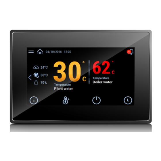
Введение
Графический сенсорный терминал pGDx диагональю 7 дюймов предназначен для
дистанционного управления контроллерами семейства pCO. Терминал поддерживает
электронную технологию, имеет высококачественный дисплей с 16.7м тысячами
цветов и обладает широким набором функций. Кроме этого, у него современный
привлекательный внешний вид. Сенсорный дисплей упрощает процесс навигации
по меню параметров, различным окнам и облегчает работу с терминалом в целом.
Существуют модели под разные варианты монтажа: спереди или сзади, настенный или
врезной монтаж. Графический терминал может устанавливаться в горизонтальном или
вертикальном положении.
Артикулы
Артикул
PGR07****B***
PGR07****W***
230
PGR07****D***
PGR07****C***
PGR07****R***
PGR07****F***
PGR07****G***
PGB07****E***
PGB07****M***
PGB07****I***
212.5
Комплект поставки
pGDx; разъем питания и порт RS485 (только в моделях с портом); крепежные винты;
техническое руководство; Антенна WiFi (только для моделей с WiFi, PG*07***D[G,I,R,W]***).
В комплект не входит: рамка, блок питания PGTA00TRX0 и настенные монтажные коробки.
200
Предупреждения по монтажу
По вопросу монтажа обращайтесь к квалифицированному специалисту.
Запрещается устанавливать графический терминал в следующих местах:
• относительная влажность воздуха выше значения, указанного в технических
характеристиках;
• сильная вибрация или удары;
• агрессивные вещества (например, пары аммиака и серы, соляной туман, дым) во
избежание коррозии и/или окисления;
• сильные электромагнитные и/или радиочастотные помехи (не устанавливайте
рядом с передающей антенной);
• прямые солнечные лучи и осадки;
• значительные и резкие колебания температуры воздуха;
176
• взрывоопасные газы или пожароопасные смеси.
Необходимо соблюдать следующие требования:
• модели со встроенным датчиком температуры/влажности рекомендуется:
– использовать только с накладными рамками с вентиляционными отверстиями;
– устанавливать вдали от воздушных потоков, входящих и выходящих из систем
отопления/охлаждения;
– при вертикальном монтаже разворачивать датчиком вниз;
221.7
• кабели Ethernet и RS485 обязательно должны быть экранированными;
• запрещается использовать источник питания, отличающийся от указанного.
В противном случае, можно повредить терминал;
• следует использовать наконечники кабелей, подходящие к соответствующим зажимам.
Ослабить винт, вставить наконечник кабеля и затянуть винт. По завершении операции
слегка потянуть кабель, чтобы убедиться в прочности соединения;
• если модель с внешней антенной WiFi, необходимо убедиться, что изоляция не менее
500В~ (по стандарту IEC 60730-1) между разъемом RP-SMA и защитным заземлением;
• запрещается снимать крышку терминала, находящегося под напряжением;
• эксплуатация терминала при очень низкой температуре может привести к понижению
скорости отклика дисплея (подтормаживанию). Это не считается признаком неисправности;
• правильный момент при затяжке 0.4 Нм. Кроме этого, чтобы класс защиты моделей
PG*07***[N,T]**** соответствовал заявленному производителем, шероховатость
поверхности панели не должна превышать 1.6 мкм, а прокладка должна быть
установлена правильно;
• запрещается любой контакт терминала с цепями под напряжением;
• кабели должны быть надежно закреплены, чтобы при случайном отсоединении
разъема они не касались цепей и устройств под напряжением.
Цвета шкалы состояния
При включении шкала состояния быстро мигает синим цветом, показывая, что
M3 self-blocking inserts
or Ø 4.2 for screw
идет загрузка. Далее состояние шкалы зависит от загруженной в память терминала
+ counter-screw
программы управления, созданной в среде c.touch.
Обновление программного и/или микропрограммного
обеспечения
1. Скопируйте архивный файл (.ZIP), содержащий
обновление программного и/или микропрограммное
Щель под
обеспечения терминала на USB-накопитель. Состав
плоский кабель
архива определяется при его создании в среде c.touch.
(только если
Подсоедините USB-накопитель к порту терминала pGDx и
подсоединяется
коснитесь дисплея на несколько секунд, чтобы открылось
внешняя
клавиатура)
показанное на рисунке справа меню:
Flat cable passage
(only in case
of external keypad)
M3 threaded pins
2. Выберите пункт "Update... " ,
чтобы начать обновление
программного и/или
микропрограммного
обеспечения. Начнется
обновление, и на дисплее
терминала появится
следующее окно.
Параметры настройки
Коснитесь дисплея терминала pGDx
на несколько секунд, чтобы открылось
показанное ниже на рисунке меню.
Настенная коробка / Wall box
Выберите пункт "Show system
standard ITA/CHN/DEU/USA
settings", и откроется окно настроек,
показанное на рисунке справа:
Ниже перечислены пункты окна настроек:
Язык
Система
Журналы
Дата и время
Сеть
Сервисы
Управление
Дисплей
Перезагрузка
Аутентификация
Выход
Порты RS485
Порты ETH
Сеть Wi-Fi
1
-
-
1
-
2
-
-
1
1
-
1
1
2
2
-
2
2
-
1
-
-
2
-
-
2
3. Следуйте
указаниям
на дисплее и
выберите файл
обновления на
USB-накопителе
и нажмите кнопку
Next, чтобы
продолжить.
Язык интерфейса (не создается в среде c.touch)
Сведения о терминале pGDx: версия BSP, объем памяти, таймеры
и датчик температуры/влажности (если установлен)
Скачивание журнала событий
Настройки даты и времени терминала pGDx (автоматически или
самостоятельно)
Текущие сетевые параметры (адрес, маска подсети, шлюз,
серверы DHCP и DNS) и меню параметров настройки порта
Ethernet и WiFi interface.
Включение и выключение различных сервисов терминала pGDX
(порт сервера Modbus, сетевой адрес терминала pGDX,...)
Обновление разделов BSP терминала pGDx (Confi gOS, MainOS,
Bootloader, Splash image и др....)
Настройки яркости, времени работы подсветки, ориентации
экрана и калибровка сенсорного экрана
Перезагрузка терминала
Настройка пароля доступа к терминалу
Выход из меню
Introduction
The pGDx 7 inch graphic terminal is part of the family of touchscreen terminals designed to
simplify user interface with the pCO sistema family controllers. The electronic technology
used and the new 16.7M colour display means high quality images and advanced functions
are available for a superior appearance. The touchscreen panel moreover makes interaction
between the user and the unit much easier by simplifying navigation between the various
screens. Diff erent types of installation are available, depending on the model: front or
back panel, wall surface or fl ush-mount. In any case, the device can be mounted either
horizontally or vertically.
Part numbers
Part number
No. RS485 ports
No. ETH ports
PGR07****B***
1
PGR07****W***
1
PGR07****D***
2
PGR07****C***
1
PGR07****R***
1
PGR07****F***
2
PGR07****G***
2
PGB07****E***
-
PGB07****M***
-
PGB07****I***
-
Packaging contents
pGDx; power supply and RS485 connectors; installation kit; technical leafl et, WiFi antenna
(only for models where fi tted, PG*07***D[G,I,R,W]***). Not included: frame, PGTA00TRX0
power supply and wall mounting boxes .
Installation warnings
For correct installation contact a qualifi ed installer.
Do not install the terminals in environments with the following characteristics:
• relative humidity greater than the value specifi ed in the technical specifi cations;
• strong vibrations or knocks;
• exposure to aggressive and polluting atmospheres (e.g.: sulphur and ammonia fumes,
salt spray, smoke) so as to avoid corrosion and/or oxidation;
• strong magnetic and/or radio frequency interference (therefore avoid installing the units
near transmitting antennae);
• exposure to direct sunlight or the elements in general;
• large and rapid fl uctuations in the room temperature;
• environments where explosives or mixes of fl ammable gases are present.
The following requirements must be met
• with built-in temperature/humidity sensor, it is recommended to:
– only use frame fi tted ventilation openings
– install the terminal away from air streams coming from heating/cooling systems
– if installed vertically, position the probe at the bottom of the display
• only use shielded cables for Ethernet and RS485 communication networks;
• power supply voltages other than those specifi ed may seriously damage the system;
• use cable ends suitable for the corresponding terminals. Loosen each screw and insert
the cable ends, then tighten the screws. When the operation is completed, slightly tug
the cables to check they are suffi ciently tight;
• in models with an external WiFi antenna, ensure at least basic insulation (500 Vac
according to IEC 60730-1) between the RP-SMA connector and the protective earth;
• do not open the product when powered;
• operation at low temperatures may cause a noticeable decline in the response speed
of the display. This should be considered normal and does not indicate a malfunction.
• for correct installation, apply a tightening torque of 0.4 Nm. Furthermore, on
PG*07***[N,T]**** models, to ensure the declared IP value, the panel roughness index
must not exceed 1.6 μm and the gasket must be fi tted correctly;
• avoid any contact of the product with live parts.
• be sure that cables are accurately fi xed in order to avoid contact with live parts in case of
their accidentally disconnection.
Meaning of the colours on the notifi cation bar
At power-on, the notifi cation bar briefl y shows a blue signal to indicate the start of the
boot phase. The subsequent signals are then managed by the application program
developed using c.touch.
HMI Runtime and/or application update
1. Copy the update package (.ZIP fi le) containing the runtime
or application, or both, depending on the options selected
when generating the "Update package" using c.touch, to a
USB pendrive and then plug the pendrive into the pGDx and
hold the pGDx terminal screen for a few seconds until the
shortcut menu is displayed, disableable application side (see
the fi gure on the side):
2. Select "Update..." to
start the Runtime and/
or application update
procedure. The update
utility will start and the
following window will
be displayed:
System settings
Touch and hold the pGDx terminal screen
for a few seconds until the shortcut
menu is displayed (see the fi gure below).
Select "Show system settings"; the main
confi guration program screen will be
displayed (fi gure on the side):
Below is a list of the functions relating to the diff erent menu items:
Language
Set the system language (not the c.touch application)
Contains information on the pGDx: BSP version, Memory, Timers
System
and temperature / humidity sensor (if featured)
Logs
Download the system log fi les
Date & Time
Set pGDx date and time using the automatic or manual procedure
Show current system IP data (address, subnet, Gateway, DHCP, DNS)
Network
and access the Ethernet and WiFi interface
Start/stop various system services (Modbus server port, pGDx
Services
network address,...)
Update the diff erent pGDx BSP partitions (Confi gOS, MainOS,
Management
Bootloader, Splash image, etc....)
Set brightness, backlight timeout, screen orientation and touch
Display
panel calibration
Restart
Restart the system
Authentication
Set the password used to access
EXIT
Exit the menu
WiFi connectivity
-
-
-
-
-
1
-
1
2
-
2
1
-
2
-
2
3. Then follow the
guided procedure,
selecting the fi le
saved on the USB
pen drive and
clicking the next
button to confi rm.
Advertisement
Table of Contents

Subscribe to Our Youtube Channel
Related Manuals for Carel pGD Touch Series


Summary of Contents for Carel pGD Touch Series
- Page 1 3. Следуйте metal panel utility will start and the pen drive and чтобы начать обновление указаниям Не входит в комплект поставки Carel / Not supplied by Carel following window will clicking the next программного и/или на дисплее и be displayed: button to confi rm.
- Page 2 CAREL can not be held responsible. The fi nal client must use the product only in the manner described in the documentation related to the product itself.
Need help?
Do you have a question about the pGD Touch Series and is the answer not in the manual?
Questions and answers