Table of Contents
Advertisement
Quick Links
Important notes to installers
The Nuaire Drimaster/Flatmaster range has been curing severe
condensation problems for over 20 years in some of the worst
affected properties throughout the world.
Its successful operation depends entirely upon the unit being
installed strictly in accordance with these instructions. We would,
therefore, respectfully suggest that you read through this guide in
its entirety before commencing installation and then go through
this guide step by step to ensure a satisfactory completion.
Whilst the installation of the Flatmaster unit may be achieved by a
suitable craftsman, the provision of the electrical supply and the
connection of the unit to the mains must be carried out by a qualified
electrician.
The unit has a 5 year warranty starting from the day of delivery and
includes parts and labour for the first year. The remaining 4 years
covers parts only. This warranty is conditional on the following:-
a) That the unit is installed strictly in accordance
with this guide.
b) That the unit filters are removed and cleaned or
replaced at the recommended intervals.
The unit represents a significant financial outlay on the part of the
user/specifier and the unique 5 year warranty is important to them.
We make a point of advising them that the installer is provided with
detailed instructions regarding installation/guarantee registration
and therefore has the responsibility of ensuring that the unit is
guaranteed for the user/specifier.
1.0 Installation
Where the systems are installed in flats where regulations require
the provision of a protected entrance hall or protected enclosure
and the outlet of the systems are within that enclosure it is
necessary to ensure that the safety of the enclosure is not
compromised either in relation to its fire resistance or the entry of
smoke. Smoke detectors must be connected to the fan so that it
shuts down if smoke enters the ductwork. Ductwork must be of
steel, with the point of fire penetration stopped, or if non
fire-resistant ducting is used, it must be protected in fire-resisting
construction up to the point where it penetrates the wall of the
protected entrance hall or protected enclosure.
Where the systems are installed in flats where these regulatory
provisions do not apply, good installation practice should be
observed; for example the use of smoke detectors to control the fan,
to ensure that occupant safety levels are not reduced.
For more information please refer to the
Building Regulations, Approved Document B (Fire safety) –
Volume 1: Dwelling houses (2006 Edition)
The unit is designed to take fresh air from outside, clean the air,
warm it (if fitted with heater) and discharge it into the central hall-
way via a system of ducting supplied by the installer. The dwelling
internal air discharge grille is usually installed at high level in a
central location within the hallway, although discharging the air
down the length of the hallway (away from the front door) should
also prove acceptable. Unit performance may be enhanced if an
existing heat source can warm the discharged air eg. by locating the
discharge grille above a radiator.
Before commencing installation decide the best position for the unit
and where the fresh air input air is to come from and be discharged to.
The unit can be installed in many different configurations and is
supplied with enough interchangeable spigots to enable it to be used
with either round (100mm) or rectangular ducting (121mm x 60mm).
The unit can be turned through 180
Nuaire Limited Western Industrial Estate Caerphilly United Kingdom CF83 1NA
T: 029 2088 5911 F: 029 2088 7033 E: info@nuaire.co.uk W: www.nuaire.co.uk
FLATMASTER
Low Energy Positive Input
Ventilation Unit
Installation and Maintenance
o
to any angle if required.
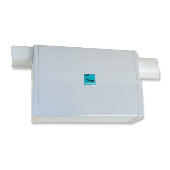
Figure 1. Typical installations show unit with top discharge.
Fixing the unit to the wall
The unit has four mounting pads. Mark through these pads when the
unit is in the correct position. Drill and plug wall with suitable fixings.
Remove PCB cover and feed the electrical supply cable through the
grommet hole (standard 1mm three core lighting cable is recommended)
in the rear of the unit screw unit to wall.
Points to consider
1.
The inlet ducting should be kept as short as possible to avoid
condensation build up on the ducting surface (see figs 5/6).
2. Can the discharge grille be located to take advantage of existing
heat sources?
3. Find the shortest, most direct route from outside of the unit and
then to the discharge grille using the least number of bends
(these bends increase the airflow resistance).
4. Note the location of any joists, pipes, electrical cables etc.
5. Allow adequate access to the front cover to allow filter cleaning?
6. Refer to the relevant Building and Electrical Regulations.
Setting up the correct airflow direction
Figure 2.
1
The EMC Directive
2004/108/EC
The Low Voltage
directive
2006/95/EC
Leaflet Number 670833 July 2009
Advertisement
Table of Contents

Subscribe to Our Youtube Channel
Related Manuals for NuAire FLATMASTER


Summary of Contents for NuAire FLATMASTER
- Page 1 Whilst the installation of the Flatmaster unit may be achieved by a suitable craftsman, the provision of the electrical supply and the connection of the unit to the mains must be carried out by a qualified electrician.
- Page 2 The outside wall input grille louvres MUST SLANT DOWNWARDS. Standard 100mm dia ducting or 121 x 60mm ducting is used to connect the Flatmaster to the input and discharge grilles. Figure 5. Side input installation. All wiring is supplied for connecting the heater to the main PCB.
- Page 3 Installation and Maintenance FLATMASTER Low Energy Positive Input Ventilation Unit Heater option wiring detail for (bathroom 3.1 Smoke alarm automatic shut down application) If the unit is required to switch off in the event of smoke detection, If units are installed in a bathroom the unit mounted heater switch alarms are available with separate relay bases from companies cannot be used.
- Page 4 Finally, thank you for taking the time to read this short user Q. How do I operate the unit? guide. If you are happy with your Flatmaster 5+ Home A. You don’t have to. From the time the installer starts the unit it Improvement Unit, please tell your friends and neighbours.
Need help?
Do you have a question about the FLATMASTER and is the answer not in the manual?
Questions and answers