Table of Contents
Advertisement
Quick Links
1.0 Introduction
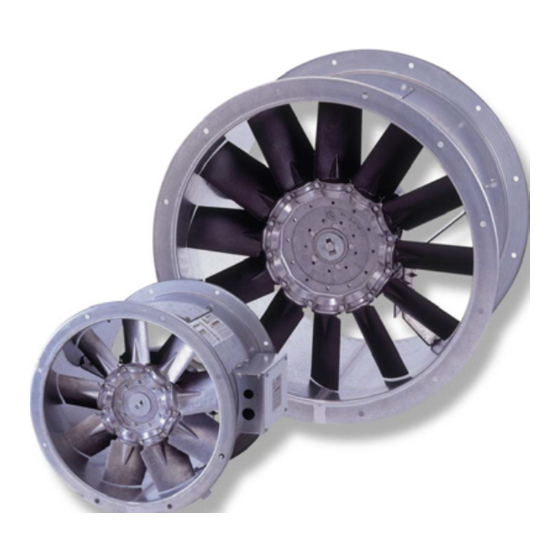
The AXUS range of axial flow fans are designed for 'in duct'
applications. Manufactured from galvanised steel, the units are
suitable for indoor or outdoor installation and at any installed
angle.
Available for single and three phase supplies.
Case diameters of 250mm to 2400mm.
Unit codes AX25 to AX240.
Impellers have been selected at blade angle settings matched to
various motor speeds to perform against the design criteria laid down
in our selection catalogue.
Any attempt to adjust or reset impeller blade angles will invalidate
For full unit description, dimensional, weight and performance details
refer to the Nuaire product catalogue. A comprehensive range of
ancillaries and silencers are also listed.
2.0 Handling
The fan impeller is carefully balanced and centralised in the fan case,
it is therefore essential that great care is exercised when handling the
unit. Check the weight on the rating plate details before attempting to
lift and always use a spreader as shown (fig. 1), never pass lifting slings
through the impeller
(fig. 2).
Figure 1. Correct method of
lifting using a spreader.
nuaire.co.uk
029 2085 8400
AXUS AX
Circular Long Cased Axial Flow Fans
Installation and Maintenance
Figure 2. The wrong method of
lifting with sling through impeller
can cause case distortion.
3.0 Installation And General Advice
Installation must be carried out by competent personnel, in accordance
with good industry practice, the appropriate authority and in
conformance with all statutory and governing regulations e.g. IEE,
CIBSE, HVCA, ATEX, BSI & EN standards etc.
If the fan is to be installed in a potentially explosive atmosphere it will
have been designed to ATEX directive 2014/34/EU and will incorporate
motors requiring compatible installation wiring direct to the motor
termination box, to complete this installation also follow the guidance
advice of data sheet 671216.
Before commencing installation check that all materials, including
optional ancillaries are available to complete the installation. Every unit
is tested and serialised at works and a test certificate produced, the
details recorded on the fan side rating plate should also be referred to
before handling and installation.
Any damages or deviations should be immediately reported to the
seller/supplier/agent quoting the order and product details from
the product rating plate.
3.1 Mechanical Installation
Rotate the fan impeller by hand to ensure free and smooth rotation and
that no transit or handling damage has occurred, observe the direction
of flow/direction of rotation arrow and ensure that:
All optional accessories such as support brackets, attenuators,
•
inlet cones, guards, flexible connectors etc. are assembled to
the fan.
The optional support brackets are correctly fitted, at any
•
position around the circumference, but suit the installation
plane.
External termination box is accessible to the electrician.
•
When offering the fan to the ducted system that both inlet
•
and outlet connections are perfectly aligned.
In order to ensure performance is as stated, a minimum
•
distance of twice the fan diameter is required between the
appliance and any bends in the ductwork.
3.2 Horizontal on Floor or Supported from Wall etc.
Optional resilient mountings should be attached to the unit mounting
brackets at this
stage (fig. 3).
If the unit is supported from a wall,
supporting brackets should be used. Position and align the unit with the
ductwork in both horizontal and vertical planes and pack height under
mounting feet if necessary.
Matching attenuators if required; should be fitted to the fan with any
other accessories before installation.
Matching flanges are fixed to the ductwork ends with rivets.
30. 04. 19. Leaflet Number 671220
The EMC Directive
2014/30/EU
The Low Voltage
Directive
2014/35/EU
1
Advertisement
Table of Contents

Related Manuals for NuAire AXUS AX Series


Summary of Contents for NuAire AXUS AX Series
- Page 1 For full unit description, dimensional, weight and performance details before handling and installation. refer to the Nuaire product catalogue. A comprehensive range of Any damages or deviations should be immediately reported to the ancillaries and silencers are also listed.
- Page 2 If the fan is to be started 3.3 Suspended Horizontally or Vertically direct on line (DOL) to a frequency inverter or Nuaire’s Ecosmart speed A.V. mountings must be arranged so that they are used in compression control the motor must be connected in Delta.
-
Page 3: Electrical Wiring
Inverters are configured to suit specific fans and control Supply: 1U 1V 1W applictions as described on the Customer Order free of charge. 400V 3 phase 50Hz supply 380V 3 phase 60Hz supply 460V 3 phase 60Hz supply nuaire.co.uk 029 2085 8400 30. 04. 19. Leaflet Number 671220... - Page 4 30 metres. Please consult also accommodate the 230V switched live (if used). Nuaire if a longer cable run is needed. The mains supply from the Ecosmart controller to the fan must be • This product must be earthed and always ‘earth’ the appropriately sized, not exceeding 30 metres and must be a screened screened cable at both ends.
- Page 5 1 – 60 minutes (see fig. 12). than 12m, Nuaire recommend using screened cable with the screening grounded at one end only (preferably at the inverter end). Do not take this signal from an isolating transformer.
- Page 6 L to the SL terminal. Unplug all items connected to the ‘Net‘ connectors. Isolation - Before commencing work, make sure that the unit, switched live and Nuaire controls are Switch on the power supply. • electrically isolated from the mains supply.
- Page 7 Clause 14 of our Conditions of Sale. Customers purchasing from Maintenance should be carried out on a regular basis, Nuaire outside of the UK should contact Nuaire International Sales office for recommend three months from commissioning and at least annually further details.
-
Page 8: Operation And Maintenance
GENERAL In addition to the particular requirements given for the individual product, the following The equipment referred to in this Declaration of Incorporation is supplied by Nuaire to general requirements should be noted. be assembled into a ventilation system which may or may not include additional Where access to any part of equipment which moves, or can become electrically live are components.
Need help?
Do you have a question about the AXUS AX Series and is the answer not in the manual?
Questions and answers