Dell EMC VEP4600 Installation Manual
Hide thumbs
Also See for EMC VEP4600:
- Installation manual (85 pages) ,
- Operating system installation manual (78 pages) ,
- Release notes (40 pages)
Table of Contents
Advertisement
Quick Links
Advertisement
Table of Contents

Related Manuals for Dell EMC VEP4600


Summary of Contents for Dell EMC VEP4600
- Page 1 Dell EMC VEP4600 Installation Guide November 2021 November 2021 Rev. A08...
- Page 2 A WARNING indicates a potential for property damage, personal injury, or death. © 2016 - 2021 Dell Inc. or its subsidiaries. All rights reserved. Dell, EMC, and other trademarks are trademarks of Dell Inc. or its subsidiaries. Other trademarks may be trademarks of their respective owners.
-
Page 3: Table Of Contents
Contents Chapter 1: About this guide......................5 Related documents................................5 Information symbols................................6 Chapter 2: VEP4600 platform......................7 Introduction................................... 7 Features....................................8 Physical dimensions................................8 LED display.................................... 8 LED behaviors.................................9 Expansion card LED behavior............................10 Pre-requisites..................................11 VEP4600 configurations..............................12 Luggage tag..................................12 Chapter 3: Site preparations......................13 Site selection..................................13 Cabinet placement................................ - Page 4 European Union EMC directive conformance statement.................. 36 Japan VCCI compliance for class A equipment....................37 Korean certification of compliance..........................37 Mexico certification of compliance......................... 38 Taiwanese certification of compliance........................38 Thailand certification of compliance........................38 Singapore certification of compliance........................39 Chapter 9: Dell EMC support....................... 40 Contents...
-
Page 5: Chapter 1: About This Guide
● VEP4600 Setup Guide ● VEP4600 Release Notes ● VEP4600 Expansion Cards Release Notes ● VEP4600 Technical Guide ● VEP4600 Diag Guide ● VEP4600 BIOS User Guide ● VEP4600 BMC User Guide NOTE: For the most recent documentation, see www.dell.com/support. About this guide... -
Page 6: Information Symbols
Information symbols This book uses the following information symbols: NOTE: The Note icon signals important operational information. CAUTION: The Caution icon signals information about situations that could result in equipment damage or loss of data. NOTE: The Warning icon signals information about hardware handling that could result in injury. NOTE: The ESD Warning icon requires that you take electrostatic precautions when handling the device. -
Page 7: Chapter 2: Vep4600 Platform
VEP4600 platform The following sections describe the Dell EMC Virtual Edge Platform 4600 (VEP4600) platform: Topics: • Introduction • Features • Physical dimensions • LED display • Pre-requisites • VEP4600 configurations • Luggage tag Introduction The VEP4600 platform is a one rack unit, x86-based networking platform running virtualized universal customer premise equipment (uCPE) functions and basic switching/routing functions as a top-of-rack device. -
Page 8: Features
Figure 3. VEP4600 PSU-side 1. PSUs 2. Fans Features The VEP4600 platform offers the following features: ● Two 10GbE SFP+ ports ● Four 1000Base-T ports ● One Micro USB type-B console port ● Two USB Type-A ports for more file storage ●... -
Page 9: Led Behaviors
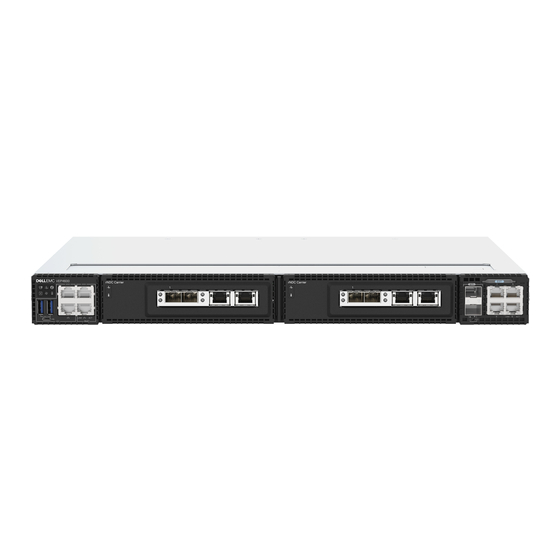
LED behaviors Figure 4. VEP4600 LEDs 1. Power LED 2. Primary unit indicator LED 3. System LED 4. Locator LED 5. Temperature LED 6. Fan LED 7. SFP+ indicator LED 8. 10/100/1000 BaseT RJ-45 networking link (left) and activity (right) LEDs 9. -
Page 10: Expansion Card Led Behavior
Table 1. VEP4600 LED behavior (continued) Description ● Flashing yellow—PSU warning event; power continues to operate LOCATOR LED/System Beacon ● Off—Locator function disabled ● Flashing blue with 1 sec on and 1 sec off – Locator function enabled ● Flashing blue with 2 sec on and 1 sec off – system in standby Temperature status LED ●... -
Page 11: Pre-Requisites
Figure 5. rNDC front panel LED call-outs Table 4. Expansion card LEDs Description 1.) System LED ● Off—Card is off ● Solid green—Normal operation ● Solid yellow—Citical card error ● Flashing green—Booting ● Flashing yellow—Noncritical card error 2.) Temperature LED ●... -
Page 12: Vep4600 Configurations
NOTE: DC PSU optional configuration offered as a custom-kit. Simply contact a Dell Sales Representative. ○ Sixteen-core systems use five fans and two AC PSUs. ○ Eight-core systems use four fans one or two AC PSUs. -
Page 13: Chapter 3: Site Preparations
Site preparations VEP4600 is universal customer premise equipment (uCPE). To connect the service provider edge or enterprise branch to the cloud, use VEP4600 to host multiple virtual network functions (VNFs), such as SD-WAN, routing, firewall, and deep-packet inspection. For more information about platform specifications, see Specifications NOTE: Install the VEP4600 in a rack or cabinet before installing the components. -
Page 14: Rack Mounting
Ground the equipment rack to the same ground point the power service in your area uses. The ground path must be permanent. Platform ground Dell EMC recommends you ground your platform. Use the VEP4600 in a common bond network (CBN). Connect the grounding cables as described in the VEP4600 installation section. . -
Page 15: Storing Components
● Short push: ○ Sends ACPI power event to the Operating System (OS.) NOTE: Response depends on configuration of how the OS is booted-up when it receives a ACPI power event. The response may ignore the button push or shutdown the system. ●... -
Page 16: Chapter 4: Vep4600 Installation
VEP Expansion Card installation The VEP4600 platform offers the following features: NOTE: Customers are not to attempt installing Virtual Edge Platform (VEP) 4600 expansion cards. A Dell EMC Certified technician must perform this installation. CAUTION: The mezzanine cards are intended for professional installation only. -
Page 17: Ground Lug
Ground lug Dell EMC recommends you ground your switch; however, grounding is optional and the ground lug assembly kit is not included with the switch. The ground lug must be a UL-recognized, crimp-type lug. To order a UL-certified ground lug with bracket, contact your Dell EMC sales representative. -
Page 18: Rack Or Cabinet Hardware Installation
Rack or cabinet hardware installation You may either place the platform on a rack shelf or mount the platform directly into a 19" wide, EIA-310- E-compliant rack. The platform includes two-post rail assemblies. WARNING: This document is a condensed reference. Read the safety instructions in your Safety, Environmental, and Regulatory information booklet before you begin. -
Page 19: Two-Post Installation
Figure 9. Reverse small bracket Figure 10. Reversed rail mounting bracket position 3. Mount unit on front-mount (flush-mount) rails. Figure 11. Platform flush-mounted on two posts Two-post installation To easily configure your rack for installation of the VEP4600, use the two-post rack mounting system provided. To complete this installation, supply four rack-mounting screws. -
Page 20: Four-Post Installation
Figure 12. Two-post rail Four-post installation To complete this installation, supply eight rack-mounting screws. NOTE: For more installation instructions, see the installation labels attached to the rail assembly. 1. Separate each rail assembly by sliding the inside rail out of the outside rail. 2. -
Page 21: Optics Installation
The VEP4600 has SFP+ optical ports. For a list of supported optics, see the specification sheets at www.dell.com/support or contact your Dell EMC Sales representative. CAUTION: ESD damage can occur if components are mishandled. Always wear an ESD-preventive wrist or heel ground strap when handling the VEP4600 and components. -
Page 22: Optics Removal
Supply power to the VEP4600 after it is mounted in a rack or cabinet. Dell EMC recommends reinspecting your platform before powering it up. Verify the following: ● Optional: The equipment is properly secured to the rack and properly grounded. -
Page 23: Chapter 5: Power Supplies
NOTE: DC PSU optional configuration offered as a custom-kit. Contact Dell EMC support site at www.dell.com/support/. Two PSUs are required for full redundancy, but the platform can operate with a single PSU. The PSUs are field replaceable and hot-swappable. When running with full redundancy—two power supplies installed and running—you can remove and replace one PSU without disrupting traffic. -
Page 24: Ac Power Supply Installation
DC PSU LEDs 1. DC PSUs ● Solid green—Input voltage ok and output good. ● Flashing yellow (amber)—There is a Standby mode or PSU failure (OC, OT, OV, Fan fault). ● Off—PSU is off. AC power supply installation NOTE: The PSU slides into the slot smoothly. Do not force a PSU into a slot as this action may damage the PSU or the platform. -
Page 25: Ac Power Supply Replacement
NOTE: If a PSU fails, you must replace the PSU unit. There are no field serviceable components in the PSU. To request a hardware replacement, see www.dell.com/support. NOTE: If you use a single PSU, install a blank plate in the other PSU slot. If you are only using one power supply, install the power supply in the first slot, PSU1. - Page 26 Figure 18. Molex terminal block 7. Tighten the screws with a number 1 Philips screwdriver on the terminal block to secure the number 10 to number 3 AWG wires. Figure 19. Tighten wires to terminal block 8. Mate the terminal block to the connector on DC PSU. Place the VEP4600 System Label from the kit on top of the DC PSU cover.
- Page 27 Figure 20. Mate terminal block to DC PSU 9. Locate the overlay label in the kit and place it over the existing label in the unit. Figure 21. DC overlay label 10. Insert DC PSUs to switch. Figure 22. Insert DC PSU to switch 11.
- Page 28 Figure 23. Ground lug 12. Attach ground wire to switch. Secure ground lug with a number 1 Philips screwdriver. Figure 24. Attach ground lug and wire to switch NOTE: Torque screws to 6-inch pounds. Figure 25. Installed DC PSU(s) Power supplies...
-
Page 29: Chapter 6: Fans
Fans The VEP4600 comes from the factory with one or two PSUs and four or five fan modules installed in the platform, depending on the configuration. The fan modules and the power supplies, which have integrated fans, are hot-swappable. In addition to the power supply modules, you can order fan modules separately to install. The VEP4600 supports airflow from the I/O side to the PSU side. -
Page 30: Fan Module Replacement
1. Fan module installation Fan module replacement To request a hardware replacement, see www.dell.com/support. CAUTION: Complete the following steps within one minute or the platform temperature could rise above safe thresholds and the platform could shut down: 1. Squeeze the two orange levers on the fan module together to unlock the module. With the two orange levers squeezed, pull and slide the fan module out of the bay. -
Page 31: Chapter 7: Management Ports
Management ports Besides the 10/100/1000Base-T RJ-45 ports, the VEP4600 provides several ports for management and storage. NOTE: The output examples in this section are for reference only. Your output may vary. Topics: • RS-232 console port access • MicroUSB-B console port access RS-232 console port access The RS-232 console port is on the I/O-side of the VEP4600. -
Page 32: Microusb-B Console Port Access
Before starting this procedure, be sure that you have a terminal emulation program already installed on your PC. Install the appropriate drivers to support the microUSB-B port. To download Dell EMC drivers, see www.dell.com/support. If your computer requires non-Dell EMC drivers, contact Dell EMC Technical Support for assistance. -
Page 33: Chapter 8: Specifications
Specifications This section lists the VEP4600 specifications. CAUTION: Operate the product at an ambient temperature not higher than 113°F (45°C). NOTE: For RoHS information, see Restricted Material Compliance Topics: • Chassis physical design • IEEE standards • Safety standards and compliance agency certifications •... -
Page 34: Ieee Standards
You must recycle or discard this platform according to applicable local and national regulations. Dell EMC encourages owners of information technology (IT) equipment to responsibly recycle their equipment when it is no longer needed. Dell EMC offers a variety of product return programs and services in several countries to assist equipment owners in recycling their IT products. -
Page 35: Agency Compliance
EEE on the environment and human health due to the potential presence of hazardous substances in EEE. Dell EMC products, which fall within the scope of the WEEE, are labeled with the crossed-out wheelie-bin symbol, as shown above, as required by WEEE. -
Page 36: Industry Canada Statement
This product is in conformity with the protection requirements of EU Council Directive 2004/108/EC on the approximation of the laws of the Member States relating to electromagnetic compatibility. Dell EMC cannot accept responsibility for any failure to satisfy the protection requirements resulting from a non-recommended modification of this product, including the fitting of non-Dell EMC option cards. -
Page 37: Japan Vcci Compliance For Class A Equipment
Equipment (VCCI). If this equipment is used in a domestic environment, radio disturbance may arise. When such trouble occurs, the user may be required to take corrective actions. NOTE: Use the AC power cords with Dell EMC equipment only. Do not use Dell EMC AC power cords with any unauthorized hardware. Figure 30. Japan: warning label Korean certification of compliance Figure 31. -
Page 38: Mexico Certification Of Compliance
Figure 32. Korean package label Mexico certification of compliance La operación de este equipo está sujeta a las siguientes dos condiciones: 1. Es posible que este equipo o dispositivo no cause interferencia perjudicial y 2. Este equipo o dispositivo debe aceptar cualquier interferencia, incluyendo la que pueda causar su operación no deseada. Taiwanese certification of compliance The Taiwanese radio certification of compliance is as follows: 台灣: 國家通訊傳播委員會... -
Page 39: Singapore Certification Of Compliance
Thailand radio compliance certificate Thailand radio compliance certificate translated Singapore certification of compliance Singapore radio compliance. Complies with IMDA Standards Registration number: N2515-19 Specifications... -
Page 40: Chapter 9: Dell Emc Support
Dell EMC support The Dell EMC support site provides documents and tools to help you use Dell EMC equipment and mitigate network outages. Through the support site you can obtain technical information, access software upgrades and patches, download available management software, and manage your open cases. The Dell EMC support site provides integrated, secure access to these services.
Need help?
Do you have a question about the EMC VEP4600 and is the answer not in the manual?
Questions and answers