Table of Contents
Advertisement
Available languages
Available languages
Quick Links
Advertisement
Chapters
Table of Contents

Subscribe to Our Youtube Channel
Related Manuals for Olimpia splendid SiOS


Summary of Contents for Olimpia splendid SiOS
- Page 1 SiOS CONTROL MANUALE CONFIGURAZIONE CONFIGURATION MANUAL...
-
Page 3: Table Of Contents
5.6 - Algoritmo controllo circolatore zona miscelata ............22 5.7 - Algoritmo controllo circolatore deumidificatori ............22 5.8 - Algoritmo controllo zona miscelata (espansioni CPCOE) ........22 5.9 - Algoritmo controllo circolatore d’aria VMC ............. 23 5.10 - Algoritmo controllo pompa di calore monoblocco ..........23 5.11 - Algoritmo controllo ventilconvettore da parete CI2 ..........23 Le istruzioni contenute nel presente documento sono dedicate SOLO al personale tecnico qualificato e abilitato alla configurazione dell’impianto. SIOS CONTROL IT- 1... -
Page 4: Avvertenze
0 - AVVERTENZE 0.1 - INFORMAZIONI GENERALI Desideriamo innanzitutto ringraziarVi per aver deciso di accordare la vostra preferenza ad un nostro prodotto. 0.2 - SIMBOLOGIA I pittogrammi riportati nel seguente capitolo consentono di fornire rapidamente ed in modo univoco informazioni necessarie alla corretta installazione, programmazione e uso in condizioni di sicurezza. 0.3 - Pittogrammi redazionali Service Contrassegna situazioni nelle quali si deve informare il SERVICE aziendale interno: SERVIZIO ASSISTENZA TECNICA CLIENTI... - Page 5 PERSONE, INCLUSO QUANTO SEGUE: 1. Documento riservato ai termini di legge con divieto di riproduzione o di trasmissione a terzi senza esplicita autorizzazione della ditta OLIMPIA SPLENDID. Gli apparecchi e i dispositivi possono subire aggiornamenti e quindi presentare particolari diversi da quelli raffigurati, senza per questo costituire pregiudizio per i testi contenuti in questo manuale.
- Page 6 2. Leggere attentamente il presente manuale prima di procedere con qualsiasi operazione (installazione, manutenzione, uso) ed attenersi scrupolosamente a quanto descritto nei singoli capitoli. 3. Conservare con cura questo libretto per ogni ulteriore consultazione. 4. Dopo aver tolto l’imballaggio assicurarsi dell’integrità dei componenti;...
- Page 7 Normative di Sicurezza vigenti nel luogo d’installazione. 10. In caso di sostituzione di componenti utilizzare esclusivamente ricambi originali OLIMPIA SPLENDID. 11. IMPORTANTE ! Per prevenire ogni rischio di folgorazione è indispensabile scollegare la spina dalla presa di corrente e/o spegnere l’interruttore generale (“OFF”) prima di...
-
Page 8: Introduzione
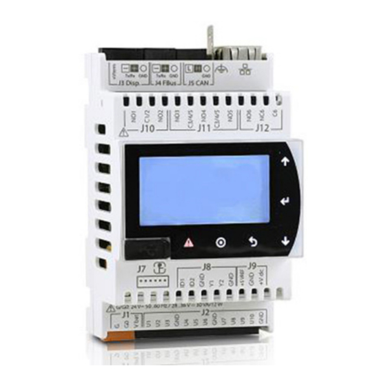
1 - INTRODUZIONE SIOS CONTROL è un sistema di gestione di un impianto di raffreddamento e riscaldamento ambiente. Il sistema è modulare, si adatta ad edifici di diverse dimensioni e permette di comandare l’impianto anche da remoto. I terminali di SIOS CONTROL consistono di: • Unità pompa di calore SHERPA, SHERPA AQUADUE, TOWER e monoblocco. • Ventilconvettori Bi2. • Ventilconvettori da parete CI2. -
Page 9: Configurazione Impianto
La configurazione dell’impianto procede passo passo, bisogna seguire le schermate una per volta fino alla fine della configurazione. In tutte le caselle che richiedono l’inserimento di un valore o la conferma di un’azione, premere il tasto ENTER per confermare. SIOS CONTROL IT- 7... -
Page 10: Configurazione Da Web Server
2.2 - Configurazione da web server RISERVATO AL PERSONALE TECNICO • Alla prima accensione si visualizza la pagina iniziale. • Con un doppio click sul campo nome “A” è possibile cambiare il nome dell’impianto. • Premendo il tasto “B” (SETUP) si accede obbligatoriamente alle pagine di configurazione impianto. Alla prima accensione Per modificare la configurazione esistente • Successivamente è sempre possibile accedere alla configurazione mediante l’icona “C” e password 829. IT- 8... - Page 11 Pagina “Configurazione terminali” (TERMINALS CONFIGURATION) • Scelta opzioni “Modalità riscaldamento” dell’edificio (HEATING MODE). Senza riscaldamento (NONE). Mediante ventilconvettori (FANCOIL). Mediante pavimento radiante (UNDERFLOOR). Mediante ventilconvettori e pavimento radiante (FANCOIL + UNDERFLOOR). • Inserire il numero della scelta nel campo OPTION e confermare con il tasto ENTER. Operare in modo analogo per la scelta della “Modalità raffreddamento” dell’edificio (COOLING MODE). In tutte le pagine • Premere il tasto Back per tornare alla pagina precedente. • Premere il tasto Forward per visualizzare la pagina successiva. SIOS CONTROL IT- 9...
- Page 12 Pagina configurazione “Pompa di calore” (HEATPUMP) Senza pompa di calore. Mediante pompa di calore modello SHERPA, SHERPA AQUADUE, TOWER e modelli S2. Mediante pompa di calore modello SHERPA (solo primo modello). 3 e 4. Per pompe di calore monoblocco. • Inserire il numero della scelta nel campo “D” OPTION e confermare con il tasto ENTER. Nel caso di pompa di calore tipo 1 e 2, una volta stabilita la comunicazione, si visualizza una seconda schermata (REGISTER) che permette di vedere il dettaglio di alcuni registri.
- Page 13 • La p resenza d i d eumidificatori p er p avimento r adiante ( IS T HERE D EHUMIDIFIER?). • La presenza di una pompa per deumidificatori (IS THERE A CIRCULATION PUMP OF DEHUMIDIFIER?). • La presenza di unità di ventilazione meccanica controllata (IS THERE VMC?). • Premere il tasto (MIXING VALVE) per visualizzare la pagina successiva. SIOS CONTROL IT- 11...
- Page 14 Pagina “Valvole miscelatrici” (MIXING VALVE) • Completare le curve climatiche delle valvole miscelatrici per espansioni ADDR001 ed ADDR002. • Premere il tasto Forward per visualizzare la pagina successiva. Pagine “Configurazione ROOM1” • A cominciare dal primo ambiente ROOM1, selezionare quali sono i ventilconvettori che appartengono a quell’ambiente (il sistema evidenza in verde le unità individuate sulla rete di comunicazione). • Selezionare a quale ventilconvettore associare la temperatura di questa stanza (ADDRESS ROOM TEMPERATURE). • Abilitare o disabilitare la visualizzazione di temperatura ambiente (ENABLE TEMPERATURE VIEW). La disabilitazione funziona solo per web server. • Una volta definiti i ventilconvettori, premere il tasto (Ci2) per visualizzare la pagina successiva.
- Page 15 (il sistema evidenzia in verde le unità individuate sulla rete di comunicazione). • Premere il tasto (ICON) per visualizzare la pagina successiva. • Associare all’ambiente un’icona mettendo la spunta nell’apposita casella. • Scrivere il nome dell’ambiente (ROOM NAME) nell’apposito spazio “E”. • Premere il tasto Forward per visualizzare le pagine relative all’ambiente successivo. • Quando sono stati configurati tutti gli ambienti, premere il tasto Forward per visualizzare la pagina “Scenario” (SCENERY). SIOS CONTROL IT- 13...
- Page 16 Pagina “Scenario” (SCENERY) • La programmazione con TIMER prevede diversi scenari a disposizione dell’utente. • Alcuni di questi hanno un setpoint preimpostato che non è modificabile dall’utente, ma è modificabile dall’installatore in fase di configurazione. • Configurare i setpoint come si desidera. • Premere il tasto Forward per visualizzare la pagina successiva. Pagina “Lingua” (LANGUAGE) • Selezionare la lingua desiderata tra quelle disponibili. • Premere il tasto Forward per visualizzare la pagina successiva. Pagina “Fine configurazione” (CONFIGURATION END) • Premere il tasto “SAVE” per salvare e uscire dalle pagine di configurazione. • In caso di necessità, prima di confermare, è possibile tornare alle pagine precedenti premendo il tasto Back. IT- 14...
-
Page 17: Cloud
Nel menù del proprio router cercare la voce INOLTRO PORTE / PORT FORWARDING / VIRTUAL SERVER ed aprire le porte 80, 443 e 21, disabilitare PROXY. SIOS CONTROL IT- 15... -
Page 18: Configurazione Cloud
3) Da ADMINISTRATION accedere alla pagina LINES, premere NEW. Compilare tutti i campi richiesti (“line code” non compilare, premere REGISTER LINE, “line type” c.Pco, “MAC” da menù INFO di B0858, “UID” da menù INFO di B0858, “Tera” da menù INFO di B0858). Dopo aver creato la LINEA, il cloud è pronto a caricare il nuovo impianto SiOS CONTROL. Il caricamento del nuovo impianto avviene in automatico. Si consiglia togliere la tensione di rete alla unità di controllo centrale B0858 e quindi riaccendere. Il caricamento del nuovo impianto potrebbe richiedere alcuni minuti. Il caricamento del nuovo impianto è da considerarsi completato quando nel... -
Page 19: App
Da APP la gestione dell’impianto è limitata ai primi 10 ambienti e le funzioni disponibili sono ridotte. • Sia il cloud che l’APP sono costantemente e frequentemente sincronizzati con web server. • Cloud, APP e web server non sono mutuamente esclusivi: possono essere tutti impiegati sullo stesso impianto. Il sistema contempla ed è in grado di gestire anche l’eventuale accesso contemporaneo allo stesso impianto. SIOS CONTROL IT- 17... -
Page 20: Logiche Di Controllo
5 - LOGICHE DI CONTROLLO 5.1 - Sherpa (ID 1026) • SIOS CONTROL comanda il modo di funzionamento standby, riscaldamento, raffreddamento. • Per comandare il solo sanitario collegare il contatto TA. • La pompa di calore gestisce autonomamente la termostatazione in base ai set point. 5.2 - Sherpa Aquadue, Sherpa Aquadue Tower (ID 1061) • SIOS CONTROL comanda il modo di funzionamento: standby, riscaldamento, raffreddamento o solo acqua sanitaria. -
Page 21: Algoritmo Controllo Circolatore Zona Diretta
• La gestione zona miscelata consiste nel controllo di temperatura ambiente, umidità ambiente e temperatura dell’acqua. ATTENZIONE La valvola miscelatrice deve essere completata con una valvola termostatica (posizionata nella tubatura di mandata) per fermare il circolatore in caso di bloccaggio della valvola miscelatrice. SIOS CONTROL IT- 19... -
Page 22: Algoritmo Controllo Circolatore D'aria Vmc
5.9 - Algoritmo controllo circolatore d’aria VMC • Il circolatore d’aria VMC dispone, a seconda dei modelli, di un ingresso Timer o Power. • All’apertura del contatto NO il circolatore d’aria è forzato spento. • Alla chiusura del contatto NO il circolatore funziona come da impostazione proprio telecomando/tastierino. • Il contatto circolatore è gestito dall’Utente acceso o spento con comando manuale o con programmazione Timer. 5.10 - Algoritmo controllo pompa di calore monoblocco • La pompa di calore monoblocco è gestita mediante i contatti: - ON/OFF (equivalente di RUN CIRCOLATORE se il contatto è chiuso, STOP se il contatto è aperto), - NORMAL/ECO MODE. - HEATING/COOLING MODE. • Nel caso uno o più unità di zona diretta (ventilconvettori, ventilconvettori da parete, termoarredo) o di zona miscelata (pavimento radiante, deumidificatore) richiedono riscaldamento/raffrescamento, l’uscita ON/OFF è attivata • Nel caso nessuna delle unità richiede riscaldamento/raffrescamento, l’uscita del... - Page 23 5.6 - Mixed zone circulator control algorithm ..............19 5.7 - Dehumidifiers circulator control algorithm .............. 19 5.8 - Mixed zone control algorithm (CPCOE expansions) ..........19 5.9 - VMC air circulator control algorithm ............... 20 5.10 - Monoblock heat pump control algorithm .............. 20 5.11 - Wall fan coil CI2 control algorithm ................ 20 The instructions contained in this document are ONLY aimed at qualified technical personnel authorized for configuration of the plant. SIOS CONTROL EN- 1...
-
Page 24: Warnings
0 - WARNINGS 0.1 - General information First of all, we would like to thank you for choosing one of our products. 0.2 - SYMBOLS The pictograms in the next chapter provide the necessary information for correct installation, programming and use in safety conditions. 0.3 - Editorial pictograms Service Refers to situations in which you should inform the SERVICE department in the company: CUSTOMER TECHNICAL SERVICE. Index Paragraphs marked with this symbol contain very important information and recommendations, particularly as regards safety. - Page 25 OLIMPIA SPLENDID. Our appliances and devices are subject to change and some parts may appear different from the ones shown here, without this affecting the text of the manual in any way. SIOS CONTROL EN- 3...
- Page 26 2. Read this manual carefully before performing any operation (installation, maintenance, use) and follow the instructions contained in each chapter. 3. Keep the manual carefully for future reference. 4. After removing the packaging, check that the components are in perfect condition. The packaging materials must not be left within reach of children as they can be dangerous.
- Page 27 14. The system must be used only according to the specifications in this manual. 15. THE MANUFACTURER IS NOT RESPONSIBLE FOR DAMAGES TO PERSONS OR PROPERTY CAUSED BY FAILURE TO FOLLOW THE INSTRUCTIONS IN THIS MANUAL. SIOS CONTROL EN- 5...
-
Page 28: Introduction
1 - INTRODUCTION SIOS CONTROL is a management system of a room cooling and heating system. The system is modular, it adapts to buildings of different sizes and also allows to control the system remotely. SIOS CONTROL terminals consist of: • SHERPA, SHERPA AQUADUE, TOWER and monoblock heat pump unit. • Fan coils Bi2. • Wall fan coils CI2. • Air circulators SITALI. • Radiant floor. • Dehumidifiers. • Decorative radiators. • Mixing valves. • Water circulators for direct zone and mixed zone. -
Page 29: Plant Configuration
Plant configuration proceeds step by step, it is necessary to follow the screens one at a time until the end of the configuration. In all the boxes which require the entry of a value or the confirmation of an action, press key ENTER to confirm. SIOS CONTROL EN- 7... -
Page 30: Configuration From Web Server
2.2 - Configuration from web server RESERVED FOR TECHNICAL PERSONNEL • The main page appears at first start-up. • With a double click on name field “A” it is possible to change the name of the system. • Press key “B” (SETUP) to access compulsorily to the plant configuration pages. At first start-up To change the current configuration • After this operation, it is always possible to access configuration by means of the icon “C” and password 829. EN- 8... - Page 31 “Configurazione terminali” (TERMINALS CONFIGURATION) page • “Modalità riscaldamento” (HEATING MODE) of the building options selection. Without heating (NONE). By means of fan coils (FANCOIL). By means of radiant floor (UNDERFLOOR). By means of fan coils an radiant floor (FANCOIL + UNDERFLOOR). • Enter the choice number in the filed OPTION and confirm with ENTER. Work in the same way to select the “Modalità raffreddamento” (COOLING MODE) of the building. In all pages • Press key Back to return to the previous page. • Press key Forward to display the next page. SIOS CONTROL EN- 9...
- Page 32 “Pompa di calore” (HEATPUMP) configuration page Without heat pump. By means of heat pump SHERPA, SHERPA AQUADUE, TOWER models and S2 models. By means of heat pump SHERPA model (first model only). 3 e 4. For monoblock heat pumps. • Enter the number of the selection in field “D” OPTION and confirm with the ENTER key. In the case of a type 1 and 2 heat pump, once communication established, a second screen (REGISTER) which allows to check the details of some registers appears. • Press key (FANCOIL) to display the next page. EN- 10...
- Page 33 “Ventilconvettori” (FANCOIL) configuration page • Set the addresses range of the fan coils of the nplant0. • Set the number of rooms into which it is desired to divide the building. • To complete the setting, check the box “SAVE”. • Press key (UNDERFLOOR) to display the next page. “Pavimento radiante” (UNDERFLOOR) page • Number of wall thermostats (NUMBER OF ALL B0860/61). • Number of mixing valves (NUMBER OF MIXING VALVE). • Use or non-use of a climate curve (CLIMATE CURVE OF MIXING VALVE). • The presence of dehumidifiers for radiant floor (IS THERE DEHUMIDIFIER?). • The presence of a pump for dehumidifiers (IS THERE A CIRCULATION PUMP OF DEHUMIDIFIER?). • The presence of a controlled mechanical ventilation unit (IS THERE VMC?). • Press key (MIXING VALVE) to display the next page. SIOS CONTROL EN- 11...
- Page 34 “Valvole miscelatrici” (MIXING VALVE) page • Complete the climate curves of the mixing valves for expansions ADDR001 and ADDR002. • Press key Forward to display the next page. “Configuration ROOM1” • Starting from the first room ROOM1, select which fan coils which are part of that room (the system highlights the detected units in green on the communication network). • Select which fan coil must be paired with the temperature of this room (ADDRESS ROOM TEMPERATURE). • Enable or disable the visualization of room temperature (ENABLE TEMPERATURE VIEW). Disabling only works for web server. • Once the fan coils are defined, press key (Ci2) to display the next page. EN- 12...
- Page 35 • Select whether hydronic splits are present or not (Ci2) by checking the desired box. • Press key (UNDERFLOOR) to display the next page, select which are the wall thermostats (B0860/61) which are part of that room (the system highlights the detected units in green on the communication network). • Press key (ICON) to display the next page. • Pair an icon with the room by checking the specific box. • Write the name of the room (ROOM NAME) in the specific space “E”. • Press key Forward to display the pages regarding the next room. • When all the room have been configured, press key Forward to display the page “Scenario” (SCENERY). SIOS CONTROL EN- 13...
- Page 36 “Scenario” (SCENERY) page • Programming with TIMER entails various sceneries at the user’s disposal. • Some of these sceneries have a preset setpoint which cannot be modified by the user, but which can be modified by the installer during configuration phase. • Configure the setpoint as desired. • Press key Forward to display the next page. “Lingua” (LANGUAGE) page • Select the desired language among those available. • Press key Forward to display the next page. “Fine configurazione” (CONFIGURATION END) page • Press key “SAVE” to save and exit from the configuration pages. • In case of need, before confirming, it is possible to return to the previous pages by pressing the key Back. EN- 14...
-
Page 37: Cloud
In case of networks different from home networks, it may become necessary to access the router configuration page to change some settings. In the menu of your router, look for the item PORT FORWARDING / VIRTUAL SERVER and open ports 80, 443 and 21, disable PROXY. SIOS CONTROL EN- 15... -
Page 38: Cloud Configuration
3) From ADMINISTRATION, access the page LINES, press NEW. Compile all the required fields (“line code” do not compile, press REGISTER LINE, “line type” c.Pco, “MAC” from menu INFO of B0858, “UID” from menu INFO of B0858, “Tera” from menu INFO of B0858). After creating the LINE, the cloud is ready to load the new SiOS CONTROL plant. Loading of the new plant occurs automatically. It is advised to remove mains voltage from the main control unit B0858 and then to reactivate it. Loading of the new plant may take a few minutes. -
Page 39: App
From APP , the plant management is limited to 10 rooms and the available functions are reduced. • Both the cloud and the APP are constantly and frequently synchronized with web server. • Cloud, APP and WEB SERVER are not mutually exclusive: they can all be used on the same plant. The system envisages and is also able to manage a possible simultaneous access to the same plant. SIOS CONTROL EN- 17... -
Page 40: Control Logics
• To only control domestic mode, connect the contact TA. • The heat pump autonomously manages thermostatation based on the set points. 5.2 - Sherpa Aquadue, Sherpa Aquadue Tower (ID 1061) • SIOS CONTROL commands the operating modes standby, heating, cooling or domestic water only. • SIOS CONTROL also commands ECO. • This heat pump model does not accept climate enabling, it does not accept NIGHT. -
Page 41: Direct Zone Circulator Control Algorithm
5.8 - Mixed zone control algorithm (CPCOE expansions) • The mixed zone control consists in the control of room temperature, room humidity and water temperature. WARNING The mixing valve must be completed with a thermostatic valve (positioned in the delivery pipe) to stop the circulator in case of locking of the mixing valve. SIOS CONTROL EN- 19... -
Page 42: Vmc Air Circulator Control Algorithm
5.9 - VMC air circulator control algorithm • The air circulator VMC is equipped with, depending on the models, a Timer or Power input. • When the contact NO is opened, the air circulator is forced off. • When the contact NO is opened, the air circulator works as set on Your remote control/keypad. • The circulator contact is managed by the User on or off with manual command or with Timer programming. 5.10 - Monoblock heat pump control algorithm • The monoblock heat pump is controlled through contacts: - ON/OFF (equivalent of RUN CIRCULATOR if the contact is closed, STOP if the contact is open), - NORMAL/ECO MODE. - HEATING/COOLING MODE. • In the event that one or more units of direct zone (fan coils, wall fan coils, decorative radiator) or mixed zone (radiant floor, dehumidifier) require heating/ cooling, the output ON/OFF is activated • If no units need heating/cooling, the circulator output is off. - Page 43 SMALTIMENTO Il simbolo sul prodotto o sulla confezione indica che il prodotto non deve essere considerato come un normale rifiuto domestico, ma deve essere portato nel punto di raccolta appropriato per il riciclaggio di apparecchiature elettriche ed elettroniche. Provvedendo a smaltire questo prodotto in modo appropriato, si contribuisce a evitare potenziali conseguenze negative per l’ambiente e per la salute, che potrebbero derivare da uno smaltimento inadeguato del prodotto. Per informazioni più dettagliate sul riciclaggio di questo prodotto, contattare l’ufficio comunale, il servizio locale di smaltimento rifiuti o il negozio in qui è stato acquistato il prodotto. Questa disposizione è valida solamente negli stati membri dell’UE. DISPOSAL This symbol on the product or its packaging indicates that the appliance cannot be treated as normal domestic trash, but must be handed in at a collection point for recycling electric and electronic appliances. Your contribution to the correct disposal of this product protects the environment and the health of your fellow men. Health and the environment are endangered by incorrect disposal. Further information about the recycling of this product can be obtained from your local town hall, your refuse collection service, or in the store at which you bought the product. This regulation is valid only in EU member states.
Need help?
Do you have a question about the SiOS and is the answer not in the manual?
Questions and answers