
Related Manuals for CSL CS203X-2


Summary of Contents for CSL CS203X-2
- Page 1 CS203X-2 EPC Class 1 Gen 2 RFID Reader User’s Manual Version 2.0 CSL: The One-Stop-Shop for RFID Solutions...
-
Page 2: Table Of Contents
4. INTRODUCTION ON APPLICATION ……………………………………..……………...………………. Basic Hardware …………………………………….…………………………………. Power Supply ………………………….………………………………….. Demo Software on PC ……………………………….………………………………… GPIO Ports Signals APPENDIX A ………………………………………..……………..………… Frequency Channel Table APPENDIX B ………………………….……….…..…………. Link Profiles of CS203X-2 RFID Reader APPENDIX C ……………………………………….…….………. Antenna Ports Operation Description... -
Page 3: Fcc And Ic Statement
USER'S MANUAL, VERSION 4.0 FCC and FCC Statement FCC regulatory conformance: This device complies with Part 15 of the FCC Rules. Operation is subject to the following two conditions: (1) This device may not cause harmful interference. (2) This device must accept any interference received, including interference that may cause undesired operation. - Page 4 USER'S MANUAL, VERSION 4.0 RF Exposure This equipment complies with FCC radiation exposure limits set forth for an uncontrolled environment. This equipment should be installed and operated with minimum distance of 30 cm between the radiator and your body. This transmitter must not be co-located or operating in conjunction with any other antenna or transmitter.
- Page 5 USER'S MANUAL, VERSION 4.0 Cet équipement est conforme aux limites d’exposition aux rayonnements de la IC établies pour unenvironnement non contrôé. Cet équipement doit être installé et fonctionner à au moins 30cm de distance d’un radiateur ou de votre corps.
-
Page 6: Introduction On Features
Introduction on Features CS203X-2 RFID Fixed Reader The CS203X-2 RFID fixed reader is a reader designed to work with an any personal computer via the ethernet connection, where the application on the PCs would control the CS203X-2 reader to perform RFID tag reading and GPIO port ON/OFF operation. -
Page 7: Product Package
USER'S MANUAL, VERSION 4.0 Product Package 3.2.1 Basic Package Content The reader package contains: • A CS203X-2 fixed reader • Power Adaptor Unit • Ethernet Cable– 1 piece... -
Page 8: Product Specification
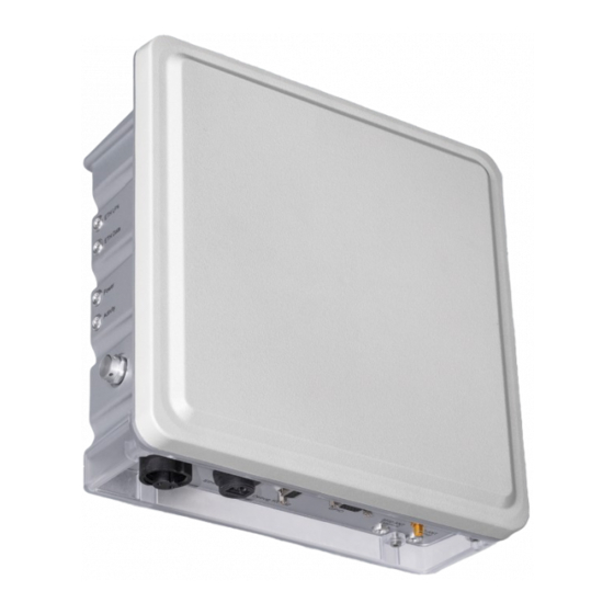
USER'S MANUAL, VERSION 4.0 Product Specification Figure 3-1 CS203X-2 Fixed Reader Features: ISO 18000-6C and EPCglobal Class 1 Gen 2 UHF RFID protocol compliant including dense reader mode Ultra long read range – peak at more than 18 meters for Monza R6 Dogbone tag ... - Page 9 EIRP Power: 902 -928 MHz band RFID Frequency Ranges: Ethernet , Debug Serial(RS232) Connectivity Accessories: Ethernet cable GPIO cable CS203X-2 Order Code: Restrictions on Use: Approvals, features and parameters may vary depending on country legislation and may change without notice...
-
Page 10: Introduction On Application
Introduction on Application Basic Hardware The CSL CS203X-2 RFID Reader is an EPCglobal Class 1 Gen 2 handheld reader product. Below is the front view of the CS203X-2 reader. There are LEDs at side to indicate the operating status Power On... - Page 11 USER'S MANUAL, VERSION 4.0 Below is the bottom-side views of the CS203X-2 reader. DC Supply Debug Serial RS232) External RF Antenna Port Antenna Port LED Ethernet Port Figure 4-2 : CS203X-2 Reader bottom-side View LED panel Figure 4-3 : CS203X-2 Reader Left-side View...
- Page 12 USER'S MANUAL, VERSION 4.0 Figure 4-4: CS203X-2 Reader Top-side View Figure 4-5: CS203X-2 Reader Rear-side View...
-
Page 13: Power Supply
Power Supply 1) Power Adaptor Unit CS203X-2 reader can be power up with the power adaptor unit included in the package. This will guarantee that CS203X-2 reader can operating in the optimal condition with its internal built-in patch antenna. Below show the typical connection to use the power adaptor. -
Page 14: 4.3 Demo Software On Pc
USER'S MANUAL, VERSION 4.0 4.3 Demo Software on PC The CS203X-2 can be controlled via the Ethernet. In this case user need to connect the PC with CS203X-2 with a Ethernet cable directly or via a router. Below is the screen capture of a Demo application, which is also available for download from Convergence website (www.convergence.com.hk), on PC controlling CS203X-2. - Page 15 USER'S MANUAL, VERSION 4.0 operations via this PC Demo application as mentioned below. Inventory Tag memory bank read and write GPIO On/Off control Antenna port settings Output power settings Fig 4-7 Main menu of PC Demo application For example, if user need to carry out inventory operation, it is necessary to click the “Inventory”...
- Page 16 USER'S MANUAL, VERSION 4.0 Fig 4-8 Inventory operation using PC Demo application...
-
Page 17: Gpio Ports Signals
USER'S MANUAL, VERSION 4.0 4.4 GPIO Port Signals Below figure shows the output and input signal for the GPIO signals. GPI : Input ports GPO : Output ports Fig 4-9 GPIO Input and Output signals... -
Page 18: Frequency Channel Table
USER'S MANUAL, VERSION 4.0 Appendix A. Frequency Channel Table FCC Band Channels Channel Frequency Channel Frequency Channel Frequency number (MHz) number (MHz) number (MHz) 902.75 911.25 919.75 903.25 911.75 920.25 903.75 912.25 920.75 904.25 912.75 921.25 904.75 913.25 921.75 905.25 913.75 922.25 905.75... -
Page 19: Link Profiles Of Cs203X-2 Rfid Reader
USER'S MANUAL, VERSION 4.0 Appendix B. Link Profiles of CS203X-2 RFID Reader Link Profile R-T Modulation DSB-ASK PR-ASK PR-ASK DSB-ASK Tari (μs) 25.00 25.00 25.00 6.25 1.00 0.50 0.50 0.50 PW (Pulse Width in usec) 12.50 12.50 12.50 3.13 RTcal (usec) 75.00... -
Page 20: Antenna Ports Operation Description
USER'S MANUAL, VERSION 4.0 Appendix C. Antenna ports operation description CS203X-2 is a reader where the ports are switched on in time one by one. At any time only 1 port is switched on and the RF power comes out only at that port.
Need help?
Do you have a question about the CS203X-2 and is the answer not in the manual?
Questions and answers