Sign In
Upload
Manuals
Brands
Arbiter Systems Manuals
Measuring Instruments
931A
User Manuals: Arbiter Systems 931A System Analyzer
Manuals and User Guides for Arbiter Systems 931A System Analyzer. We have
3
Arbiter Systems 931A System Analyzer manuals available for free PDF download: Operation Manual, Application Note
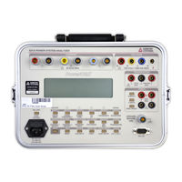
Arbiter Systems 931A Operation Manual (161 pages)
Power System Analyzer
Brand:
Arbiter Systems
| Category:
Measuring Instruments
| Size: 3 MB
Table of Contents
Table of Contents
7
1 General Information
17
Scope
17
Supplied Equipment
17
Available Accessories
18
2 Functional Description
19
Introduction
19
Inputs
19
Voltage
19
Current
19
Model 931A Front Panel
20
Transducer
21
Timer
21
Measurement Channels
21
Input Multiplexing
21
Measurement Method
22
AC Measurement Configurations
22
Sampling and Filtering
24
User Interface
24
Graphics Display
24
Keypad
25
RS-232C Interface
25
Power Supply and Battery
25
Battery Power
25
Line Power/Battery Charging
26
RS-232C Port Pinout / Signal Description
26
Auto-Shutdown Mode
27
Start-Up Sequence
27
Holding the Start-Up Sequence
27
Reset - Instrument Default Setup
27
3 Operation
29
Introduction
29
Front Panel Connections
29
Chassis Ground
29
Voltage Inputs
30
Current Inputs
30
Transducer Inputs
31
Timer Inputs
31
Front Panel Keys
31
Main Functions
31
Phase, Power Factor, and VAR Definitions
35
Phase, Power Factor, VAR Quadrants
36
Phase Angle Preferences
36
Channel 2, AC Voltage Ranges, Vrms
39
Channel 2, AC Current Ranges, Arms
39
Channel 2, DC Voltage Ranges, VDC
39
Secondary Functions
42
Three-Phase Measurement Selection
44
Three Phase Display Selection
44
Three Phase Tabular Display
44
Three-Phase Displays for an ABC System
48
Three-Phase Displays for a CBA System
49
Channel 1, AC Voltage Ranges, Vrms
53
Channel 1, AC Current Ranges, Arms
53
Channel 1, DC Voltage Ranges, VDC
53
Data Entry Functions
57
Timer Control Functions
58
Front Panel Display
60
Direct Measurements
60
AC Voltage Measurement
60
AC Current Measurement
62
DC Voltage Measurement
64
Frequency Measurement
65
Harmonic Measurement
66
Combined Measurements
68
Phase Angle Measurement
68
Active Power - Reactive Power
70
Phase Angle Example
70
Phase Convention
70
Apparent Power - Power Factor
72
Waveform Display
74
Timer Measurements
74
Connecting the Inputs
75
Configuring the Timer
75
Timer Measurement Categories
78
Transducer Testing
80
Configuring the Transducer
80
Connecting the Inputs
86
Connecting the Outputs
91
Performing the Measurement
91
Custom Pulse, or Contact Output Tests
91
Performing a Test
96
Using External Pt's and Ct's
100
Data Logging
100
Capturing Data
100
Reviewing Data
101
Erasing Logged Data
102
Printing / Exporting Data
102
Print / Data Export Setup
102
ASCII Format
103
Graphics Format (FX-80)
103
Bitmap
103
Spreadsheet
104
Initiating Printing / Exporting
113
4 Specifications
115
Inputs
115
Voltage
115
Current
115
Transducer
115
Timer
116
Measurements
116
Voltage and Current
116
Phase Angle
116
Frequency
117
Timer
117
Transducer
117
Harmonics
117
Power Quantities
117
General Specifications
118
Measurement Bandwidth
118
Memory
118
Display
118
Keypad
118
Environment
118
Input Power
119
Serial Port
119
A RS-232C Commands
121
Introduction
121
Serial Port Examples
122
Command Summary
123
Battery Charging Status (BAT)
123
Backlight Set (BLT)
123
Channel Calibrate (CCH)
123
Ratio CH1/CH2 (CCR)
124
Channel Input Select (CHS)
124
Calibrate Input (CIN)
125
Transducer Configuration (COT)
125
Daylight Saving Time, Set (DAY)
126
Display Dump, ASCII (DDA)
126
Data Dump, Bitmapped (DDB)
127
Store Calibration Data in EEPROM (EEP)
127
DSP Frequency Calibrate (FRD)
127
Frequency, Return (FRQ)
127
Timer Calibrate (FTM)
128
Harmonics Display (HAR)
128
Harmonic Magnitude, Return (HMA)
128
Harmonic Phase Angle, Return (HPH)
129
Power down (KIL)
129
Log Data (LOG)
129
Last Setup (LSU)
129
Magnitude (Channel), Return (MAG)
130
Measure Hold (MHD)
130
MIN/MAX, Display (MMN)
130
Bandwidth-Narrow, Set (NAB)
130
Overload Status (OVD)
131
Phase/Frequency Display (P F)
131
Power/Vars Display (P V)
131
Power Factor, Return (PFA)
131
Phase Mode, Set (PHM)
132
Phase, Return (PHS)
132
Power, Return (PWR)
132
Range Hold, Set (RHD)
133
Logged Data, Review (RLD)
133
Range Hold, Release (RRH)
133
MIN/MAX, Restart (RST)
133
Transducer Channel (SCC)
134
Serial Number (SER)
134
Flash Log (SLO)
134
Scale On/Off (SOO)
135
DSP Speed (SPD)
135
Phase Preference, Set (SPH)
135
Range, Set (SRG)
136
Scale Factors, Set or Return (SSC)
136
Store Setup (SST)
137
Setup, Recall (SUP)
137
Timer, Arm (TAM)
137
Time, Return (TDR)
137
Time, Set (TDS)
137
Timer Configuration, Set or Return (TCF)
138
Transducer Display (TDU)
138
Timer Display (TIM)
139
Timer Reading, Return (TMR)
139
Timer, Reset (TRS)
139
Timer, Stop (TSP)
139
Timer, Start (TST)
139
Volts/Amps Display (V A)
139
VA/PF Display (V P)
140
Volt-Amps, Return (VAM)
140
VARS, Return (VAR)
140
Version, Return (VER)
140
Waveform Display (WAV)
141
Bandwidth Wide, Set (WIB)
141
Transducer Input, Display (XDI)
141
Transducer Output, Display (XDO)
141
B Optional Accessories
143
Precision Current Transformer
143
Specifications
143
Input Connections
143
Current Display
144
Handle/Bail
144
Parts and Accessories
144
Required Tools
144
Procedure
144
Operation
144
Extended Memory
145
Data Organization
146
Computing the Number of Files and Records
148
Custom Data Table
148
Log Data Triggering
149
Front Panel Operation
150
Remote Operation
151
Setup of Logged Data Operation
151
Review of Logged Data
153
Trigger Remote Data Logging
154
C CE Mark Certification
155
Advertisement
Arbiter Systems 931A Operation Manual (146 pages)
Power System Analyzer
Brand:
Arbiter Systems
| Category:
Measuring Instruments
| Size: 1 MB
Table of Contents
Table of Contents
5
General Information
9
Scope
9
Equipment Supplied
9
Accessories Available
9
Accessories Available - Continued
10
Functional Description
11
Scope
11
Inputs
11
Voltage
11
Current
11
Transducer
11
Timer
11
Measurement Channels
13
Measurement Method
15
Sampling and Filtering
15
User Interface
16
Graphics Display
16
Keypad
16
Rs-232C Interface
17
Power Supply and Battery
18
Battery Power
18
Line Power/Battery Charging
18
Auto-Shutdown Mode
18
Start-Up Sequence
19
Holding the Start-Up Sequence
19
Operation
20
Introduction
20
Front Panel Connections
20
Chassis Ground
20
Voltage Inputs
21
Current Inputs
21
Transducer Inputs
21
Timer Inputs
22
Front Panel Keys
22
Main Functions
22
Measure Hold
29
Secondary Functions
33
Tabular Display
35
Print Log
42
Store Setup
42
Data Entry Functions
44
Left Arrow
44
Down Arrow
44
Right Arrow
45
Timer Control Functions
46
Front Panel Display
47
Direct Measurements
47
AC Voltage Measurement
48
Input Connections
48
Configuring the Channels
48
Performing the Measurement
49
AC Current Measurement
49
Configuring the Channel
50
DC Voltage Measurement
51
Frequency Measurement
52
Harmonic Measurement
53
Combined Measurements
55
Connecting the Inputs
56
Phase Angle Measurement
56
Active Power - Reactive Power
59
Apparent Power - Power Factor
60
Waveform Display
62
Timer Measurements
63
Connecting the Inputs
63
Configuring the Timer
63
Measurement Categories
67
Time Measurements
68
Transducer Testing
68
Configuring the Transducer
69
Input Mode
69
Input Type
71
Input Range
72
Output Range
73
Connecting the Inputs
74
Connecting the Outputs
81
Performing the Measurement
81
Custom Pulse, or Contact Output Measurements
81
Contact Closures
84
Equipment Setup
85
Performing a Test
86
Using External Pt's & Ct's
90
Data Logging
90
Capturing Data
90
Reviewing Data
91
Printing / Data Export
92
Print / Export Setup
92
ASCII Format
93
Graphics (FX-80)
93
Bitmap
93
Spreadsheet
94
Standard Data
94
Harmonic Data
100
Waveform Data
101
Initiating Printing / Exporting
102
Specifications
103
Inputs
103
Voltage
103
Current
103
Transducer
103
Timer
104
Measurements
104
Voltage and Current
104
Phase Angle
104
Frequency
104
Timer
105
Transducer
105
Harmonics
105
Power Quantities
105
General Specifications
106
Measurement Bandwidth
106
Memory
106
Display
106
Keyboard
106
Environment
106
Input Power
107
Serial Port
107
Appendix A. Rs-232C Commands
108
Minimum and Maximum
108
Serial Port Examples
109
Command Summary
110
Battery Charging Status
110
Calibrate Input
111
MIN-MAX-Display
117
Overload Status
117
Logged Data-Review
119
Flash Log
120
Setup-Recall
122
Timer Display
124
Volts/Amps Display
124
Appendix B. Optional Accessories
127
Precision Current Transformer
127
Specifications
127
Input Connections
127
Display
127
Handle/Bail
128
Parts and Accessories
128
Required Tools
128
Procedure
128
Operation
128
Extended Memory
130
Data Organization
130
Computing the Number of Files and Records
134
Log Data Triggering
134
Front Panel Operation
134
Remote Operation
136
Setup of Logged Data Operation
136
Review of Logged Data
138
Trigger Remote Data Logging
139
Index
140
Limited Warranty
145
Arbiter Systems 931A Application Note (6 pages)
Using Clamp-On Current Transformers CTs with Arbiter Power Analyzers, Three-Phase
Brand:
Arbiter Systems
| Category:
Measuring Instruments
| Size: 0 MB
Advertisement
Advertisement
Related Products
Arbiter Systems 940A
Arbiter Systems Portable Power Sentinel 933A
Arbiter Systems 928A
Arbiter Systems 918B
Arbiter Systems 1092A
Arbiter Systems 1092B
Arbiter Systems 1092C
Arbiter Systems 1093A
Arbiter Systems 1093B
Arbiter Systems 1093C
Arbiter Systems Categories
Clock
Measuring Instruments
Multimeter
Test Equipment
Amplifier
More Arbiter Systems Manuals
Login
Sign In
OR
Sign in with Facebook
Sign in with Google
Upload manual
Upload from disk
Upload from URL