Fema Electronica M Series User Manual
Chronometer, time counter
Hide thumbs
Also See for M Series:
- User manual (24 pages) ,
- User manual (16 pages) ,
- User manual (24 pages)
Table of Contents
Advertisement
Quick Links
Series M . M60-CR
Chronometer, time counter
PANEL MEtERS
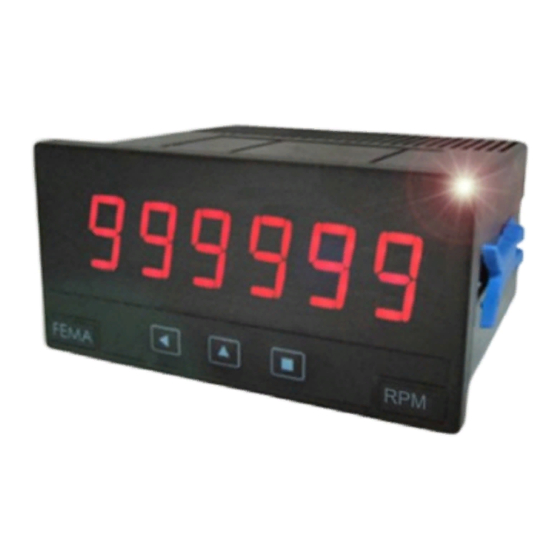
Chronometer and time counter, with 14 mm digit height. Configurable with up and down counting
modes. Independent controls for start, stop and reset. Display modes in decimal format and sexag-
esimal (clock) format. Standard 96 x 48 mm size (1/8 DIN). Reading with 6 digit display. Fast access to
alarm setpoints, special modes for counting exceeded time and totalized counting times, 'on power
up' function, configurable led brightness. Universal AC and DC power. Up to 3 optional modules for
output and control (relays, analog outputs, Modbus RTU communications, RS-485 ASCII, RS-232, ...).
3215r04
ELECTRONICS
FOR
PANEL METERS . SIGNAL CONVERTERS . LARGE DISPLAYS
Tel. (+34) 93.729.6004 info@fema.es
User's Manual
INDUSTRIAL
AUTOMATION
www.fema.es
Advertisement
Table of Contents

Related Manuals for Fema Electronica M Series


Summary of Contents for Fema Electronica M Series
- Page 1 User’s Manual ELECTRONICS INDUSTRIAL AUTOMATION PANEL METERS . SIGNAL CONVERTERS . LARGE DISPLAYS Series M . M60-CR Chronometer, time counter PANEL MEtERS Chronometer and time counter, with 14 mm digit height. Configurable with up and down counting modes. Independent controls for start, stop and reset. Display modes in decimal format and sexag- esimal (clock) format.
-
Page 2: Panel Meter M60-Cr
FEMA ELECTRÓNICA . Series M . M60-CR 1. Panel meter M60-CR Chronometer and time counter, size 96 x 48 mm (1/8 DIN) Panel meter 96 x 48 mm (1/8 DIN) and 6 digits with 14 mm digit Flash height, and function chronometer and time counter. Time displayed Several options allow to configure the display flash in case of ‘stop’... -
Page 3: Table Of Contents
FEMA ELECTRÓNICA . Series M . M60-CR Index 1. Panel meter M60-CR ..... . 2 1.13 Full configuration menu ....14 1.1 How to order . -
Page 4: Included Functions
FEMA ELECTRÓNICA . Series M . M60-CR 1.2 Included functions 1.4 Front view Alarms Control led* Functions included Section Fast access yes, configurable 1.12.5 Preset yes, configurable 1.12.1 yes, configurable : front, Reset rear and/or linked to alarm activation Logo Units Counting direction up or down... -
Page 5: Control Connections
FEMA ELECTRÓNICA . Series M . M60-CR 1.7 Types of reset 1.6 Control connections The reset function can be activated from three independent and con- • Normal connections (‘con.a’) - controls for ‘start’, ‘stop’ and ‘re- figurable sources: set’ are independent. Activation by default is by falling edge (by short-circuit to the 0 Vdc terminal). -
Page 6: Technical Specifications
FEMA ELECTRÓNICA . Series M . M60-CR 1.8 Technical specifications Digits Mechanical number of digits mounting panel 7 segments led connections plug-in screw terminal color red or green housing material ABS, polycarbonate (V0) digit height 14 mm weight <150 grams front size 96 x 48 mm (1/8 DIN) Reading modes... -
Page 7: How To Operate The Menus
FEMA ELECTRÓNICA . Series M . M60-CR 1.10 How to operate the menus The instrument has two menus accessible to the user : Example of operation inside the ‘configuration menu’. ‘Configuration menu’ (key SQ) (<) 1. The SQ (<) key enters into the ‘Fast access’... -
Page 8: Configuration Menu
FEMA ELECTRÓNICA . Series M . M60-CR 1.12 Configuration menu 1.12.1 Initial set-up Press ‘SQ’ (<) for 1 second to access the ‘configuration menu’. For a description on how to operate inside the menus see section 1.10 . For a full vision of the ‘configuration menu’ structure see To configure the initial set up of the instrument, select the viewing 1.13 section... - Page 9 FEMA ELECTRÓNICA . Series M . M60-CR 1.12 Configuration menu (cont.) • the ‘State’ (‘StAt’) parameter controls the state of the counter after power-up. Select ‘Strt’ to count after power-up or ‘StoP’ to remain stopped after power-up. ‘Flash on stop’ Flash The whole power-up process of the instrument is explained as fol- lows : instrument waits the time defined at ‘Delay’, it then resets (or...
-
Page 10: Controls Configuration
FEMA ELECTRÓNICA . Series M . M60-CR 1.12 Configuration menu (cont.) • function ‘B.4 exceeded’ (‘Fn.b.4’) enables an internal counter for exceeded time, which can be made visible on display by activation of channel ‘B’ signal. To reset the exceeded counter, view the counter Function B.4 Format on display and activate the reset (front or rear). -
Page 11: Alarms
FEMA ELECTRÓNICA . Series M . M60-CR 1.12 Configuration menu (cont.) els, value ‘on_h’ activates the reset on high signal value, and value Trigger level (from ‘on_0’ activates reset on low signal. Front reset activates always by 0 to 31). Each state. -
Page 12: Fast Access
FEMA ELECTRÓNICA . Series M . M60-CR 1.12 Configuration menu (cont.) • at ‘Activation delay’ (‘dEL.0’) configure the delay to apply before alarm activation. The activation delay starts counting when the set- point value is passed. Value from 0.0 to 99.9 seconds. Activation delay •... -
Page 13: Super Fast Access
FEMA ELECTRÓNICA . Series M . M60-CR 1.12 Configuration menu (cont.) 1.12.6 Super fast access If only a single function is selected for the ‘fast access’ menu, press- ing the the ‘UP’ (5) key will shortly display the function name and then automatically jump to the function value. -
Page 14: Full Configuration Menu
FEMA ELECTRÓNICA . Series M . M60-CR 1.13 Full configuration menu Press ‘SQ’ (<) for 1 second to access the ‘Configuration menu’. See 1.12 section for a description of each menu entry. Function on channel ‘B’ 0.00.00 to 99.59.99 Function View format 0.00.00 to 99.59.59 mode... - Page 15 FEMA ELECTRÓNICA . Series M . M60-CR 1.13 Full configuration menu (cont.) ‘Start’ Alarms Disabled Alarm 1 Alarm mode Normal Function B.5 ‘hold’ Repeat Type of alarm Function B.6 ‘Max / min’ Setpoint Activation delay No pull Pulls for Controls Pull up ‘Start’...
-
Page 16: Factory Configuration
FEMA ELECTRÓNICA . Series M . M60-CR 1.13 Full configuration menu (cont.) Configuration menu for the module installed at Opt.2 Key UP Tools Setpoint 1 Option 2 (‘Fast access’) Configuration menu for the module installed at Opt.3 Setpoint 2 Option 3 Setpoint 3 1.14 Factory configuration Function mode... -
Page 17: Application Example 1
FEMA ELECTRÓNICA . Series M . M60-CR 1.15 Application example 1 1.16 Application example 2 In an industrial process of electrolytic bath, the wetted parts need An industrial process has an oven to dry different elements. The dry- to be removed from the bath and replaced with new parts every 20 ing time of each element is variable, and the operator requires that minutes. -
Page 18: To Access The Instrument
Operation must be performed by qualified personnel only. 1.18 Modular system M Series panel meters are designed to create a modular system. This modular system allows for addition, replacement or substitution of any of the internal modules conforming the instrument. Below is a graphic explanation for the position of each module. -
Page 19: Precautions On Installation
FEMA ELECTRÓNICA . Series M . M60-CR 1.19 Precautions on installation soon as power is connected. The instrument does not have protection fuse, Risk of electrical shock. Instrument terminals can be connected the fuse must be added during installation. to dangerous voltage. The instrument is designed to be panel mounted. -
Page 20: Output And Control Modules
2.1 Module R1 2.2 Module AO The R1 module provides 1 relay output to M Series panel meters. The AO module provides 1 analog output with 4/20 mA or 0/10 Vdc Up to a maximum of 3 R1 modules can be installed in a single instru- configurable output range. -
Page 21: Module Rtu
(20 mm digit height) and BDF Series (60 mm and 100 mm digit installed (see section 1.18). height). The RTU module can be ordered pre-installed into a M Series panel • Access to display values, alarm status, memory of maximum and meter, or standalone for delayed installation, as it does not require minimum, alarm setpoints, ... -
Page 22: Module S2
(see section 1.18). The R2, R4 and R6 modules can be ordered pre-installed into a M The S2 module can be ordered pre-installed into a M Series panel Series panel meter, or standalone for delayed installation, as they do meter, or standalone for delayed installation, as it does not require not require soldering or special configuration. - Page 23 FEMA ELECTRÓNICA . Series M . M60-CR...
-
Page 24: Other Options
FEMA ELECTRÓNICA . Series M . M60-CR 3. Other options 3.1 Option NBT 3.3 Option G Instruments without front key- Green led digits option. pad. To configure the instrument, remove the meter from the panel and remove the front filter. Inter- nal press buttons for configuration are accessible. -
Page 25: Accessories
4.3 Adapter DRA-M Benchtop housing for M Series Adapter for DIN rail mount, for and K Series panel meters. Handle M Series and K Series panel me- with three selectable positions. ters. Power connector with manual switch and fuse holder. - Page 26 FEMA ELECTRÓNICA . Series M . M60-CR Notes...
- Page 27 FEMA ELECTRÓNICA . Series M . M60-CR Notes...
- Page 28 Panel meters Panel meters Signal converters Standard 96 x 48 mm Miniature 48 x 24 mm Panel meters Large format meters Bar meters Compact 72 x 36 mm ‘Customized’ Isolators Low cost instruments MODBUS TrueRMS TrueRMS RS-485 Load FEMA ELECTRÓNICA, S.A. Altimira 14 - Pol.
Need help?
Do you have a question about the M Series and is the answer not in the manual?
Questions and answers