
Related Manuals for Cosen C-260NC


Summary of Contents for Cosen C-260NC
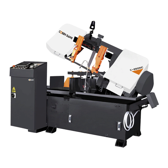
- Page 1 COSEN SAWS C-260NC SNC‐100 Programmable Automatic Mass Production Horizontal Bandsaw (CE & Non‐CE Models) Instruction Manual The Pinnacle of Cutting Performance Cosen Mechatronics Co., Ltd. ...
- Page 2 ...
- Page 3 FROM THE MANUFACTURER Thank you for your purchase of COSEN’s bandsaw machine and your trust in the COSEN brand. We are excited to have you as our valued customer and look forward as much as you do to the accelerated productivity, long-lasting endurance and superb cost-effectiveness this machine is about to bring to you.
- Page 4 ...
- Page 5 Safety rules Make sure your work area is cleared of uninvited people and obstacles every time before you start operating the machine. Never step or stand on the roller table. Your foot may slip or trip on the rollers and you will fall.
- Page 6 Safety rules Never adjust the wire brush or remove chips while the saw blade is still running. It is extremely dangerous if hands or clothing are caught by the running blade. Stop the saw blade before you clean the machine. It is dangerous if hands or clothing are caught by the running blade.
-
Page 7: Table Of Contents
Table of Contents Safety Information Section 1 – Safety Instructions ……………………………………………………………………………………………………… 1-1 Safeguard Devices ………………………………………………………………………………………………………. 1-3 Illustration: Safety Fence ………….……………………………………………………………………………..… Emergency Stop …………………………………………………………………………………………………………. 1-5 Illustration: Emergency Stop ……………………………………………………………………………………… Safety Labels ………………………………………………………………………………………………………………. 1-7 Illustration: Safety Labels ………………………………………………………………………………………..… Hearing Protection ……………………………………………………………………………………………………... 1-9 CE Compliance ……………………………………………………………………………………………………………. - Page 8 Table of Contents Control Buttons ……………………………………………………………………………………….…….. 4-5 Blade Descend Pressure & Speed ………..…………………………………………………….…… 4-7 HMI Touch Screen & Functions …………………………………………………………….………… 4-7 HMI Error Codes ………………………..……………………………………………………….…………. 4-17 Standard Accessories ………….………………………..……………………………………………….…………… 4-18 Optional Accessories …….…….………………………..…………………………………………….……………… 4-20 Unrolling & Installing the Blade …………………………………………………………………….……………. 4-21 Adjusting Wire Brush ………..……………………………………………………………………….……………….
- Page 9 Table of Contents Every Six Months ……………….……….………………………………………….……………………… 8-3 Storage Conditions …………………………..…………..………………………………………………………….. 8-3 Terminating the Use of Machine ……..……………..………………………………………………………….. 8-3 Oil Recommendation for Maintenance …………..………………………………………………………….. 8-4 Troubleshooting Section 9 – Introduction ……………………….…….……………………………………………………………………………….. 9-1 Precautions ………………….…………………..…………….………………………………………………………..9-2 General Troubles & Solutions ………………………..….……………………………………………………….. 9-2 Minor Troubles &...
-
Page 11: Safety Information
Section 1 SAFETY INFORMATION SAFETY INSTRUCTIONS SAFEGUARD DEVICES EMERGENCY STOP SAFETY LABELS HEARING PROTECTION CE COMPLIANCE RISK ASSESSMENT Safety is a combination of a well‐designed machine, operator’s knowledge about the machine and alertness at all times. COSEN’s band machine has incorporated many safety measures during the design process and used protective devices to prevent personal injuries and potential risks. Warning labels also serve as a reminder to the operator. Throughout this manual, you will also see various safety‐related symbols indicating important information that you should take note of prior to use of the machine or part of its functions. These important safety instructions do not cover all possible situations that might occur. It is your responsibility to take caution and follow procedures stated in this manual when installing, maintaining and operating your machine. Cosen will not be liable for damages resulting from improper use. SAFETY INSTRUCTIONS What the icons and signs in this user manual mean: This icon marks DANGER; hazards or unsafe practices that may result in severe personal injury or death. This icon marks WARNING; hazards or unsafe practices that may result in personal injury or damage to the machine. This icon marks CAUTION; information that should be read before use to prevent damage to the machine. Supplementary information to the procedures described in this manual. Call your local agent or our service center for help. ... - Page 12 This manual has important safety All users must read it before performing any information. Read through it carefully activity on the machine, such as replacing before operating this machine to prevent the saw band or doing regular maintenance. personal injury or machine damage. Learn the operation, limitation and the specific Some personal protective equipment is potential hazards peculiar to this band required for the safe use of the machine, e.g. protection goggles. saw. Do not operate this machine unless it is Keep blade protection cover and wheel completely assembled. covers in place and in working order. Make sure the power switch is off before Use recommended accessories. Improper plugging in power cord. accessories may be hazardous. Disconnect the power cord before making Keep your work area well illuminated at adjustment, maintenance or blade minimum 500 lumen. changes. Keep your work area clean. Cluttered and Keep all guards and shields in place before slippery floors invite accidents. installing or starting up the machine. Remove adjusting keys, wrenches or any Wear proper apparel during operation loose parts or items from the machine and when servicing the machine. ...
-
Page 13: Safeguard Devices
SAFEGUARD DEVICES The safeguard devices incorporated in this machine include the following two main parts: 1. Protection covers & guards 2. Safety‐related switches Protection Covers & Guards 1. Idle wheel housing cover 2. Drive wheel housing cover 3. Gear reducer cover 4. Wire brush belt cover 5. Blade guard cover (left & right) 6. Safety fence (left & right) (CE model only, as shown in Illustration: Safety Fence) 7. Chip conveyor cover (CE model only) The protection devices should always be mounted on the machine whenever the machine is running. Do not remove any of these safeguard devices under any circumstances except when servicing the machine. Even skilled service technicians should still take cautions when performing repairs or service on the machine with any of these protectors removed. It is the responsibility of the user to make sure all these elements are not lost and damaged. Take note of the following main moving parts on the machine prior to and during machine operation: Saw bow assembly Drive and idle wheels Blade guide arm Saw blade guide rollers ... -
Page 14: Illustration: Safety Fence
Illustration: Safety Fence Safety Fence Safety Fence 1‐4 ... -
Page 15: Emergency Stop
Safety Related Switches To protect the operator, the following safety related switches on the machine are actuated when the machine is in operation. Wheel motion detector This is a proximity sensor used to detect the motion of the drive wheel. Once the saw blade is broken or as soon as it starts slipping, the sensor will detect and stop the drive wheel and the machine. Power switch Located on the cover of electrical cabinet, the power switch controls the main power of the machine. Up to your company’s internal rules, this power switch can be locked with a padlock or a luggage lock to protect the operator and the machine. Emergency stop button Located on the control panel, the button when pressed will stop the machine completely. Vise clamp switch This switch assures firm clamping of the workpiece. If the workpiece is not clamped properly, the saw blade is not allowed to run. Wheel cover interlock switches Located on the two wheel housings, these switches (CE model only) are used to assure that the machine will stop whenever the wheel covers are open. This device is to protect users from being cut by the running saw blades. Among all these safety switches, some of them are used to protect the users and some of them are used to prevent damage to saw blades, the workpiece and the machine itself, etc. We have taken every precaution to prevent injury or damage and to provide safe and economical operation of the machine. EMERGENCY STOP Designed to be easily accessible, the emergency stop button is located on the left bottom corner on the control panel and is made in red color and rubber material. For CE models, supplementary emergency stop button may be available at other area(s) of the machine depending on machine type. ... -
Page 16: Illustration: Emergency Stop
Illustration: Emergency Stop Emergency Stop Button 1‐6 ... -
Page 17: Safety Labels
SAFETY LABELS Please read through and understand these safety labels before operating the machine. Refer to Illustration: Safety Labels. Label Meaning Label Meaning Impact Hazard Read Operator’s Manual WEAR SAFETY SHOES. Do This manual has important safety not approach dropping area information. Read through it during operation. carefully before operating this machine to prevent personal injury or machine damage. Keep Unauthorized Do not step. Personnel Away Do not stand on the machine or on the accessories! DANGER: Running Blade Cutting Hazard Blade runs through this KEEP COVER CLOSED / KEEP HAND area. Keep your hands away OFF while the blade is running. ... -
Page 18: Illustration: Safety Labels
Illustration: Safety Labels 1‐8 ... -
Page 19: Hearing Protection
Parts not assembled tightly causing mechanical vibration Our products pass noise testing less than 78 dBA. Noise level vary according to working conditions and we recommend ear plugs or other hearing protection at all time. If your machine produces an undesirable noise while it is running, you should: Make sure all maintenance tasks have been performed following the prescribed maintenance schedule (Refer to Section 8). If maintenance does not seem to solve the problem, follow the troubleshooting procedures under Section 9. CE COMPLIANCE Cosen’s CE model is designed to satisfy regulations of the Council Directive on the approximation of the laws of the Member States relating to machinery (2006/42/EC) ‐ Annex I Essential health and safety requirements relating to the design and construction of machinery. RISK ASSESSMENT Risk assessment generally takes account of intended use and foreseeable misuse, including process control and maintenance requirements. We made every effort to avoid any personal injury or equipment damage during the machine design stage. However, the operator (or other people) still needs to take precautions when handling any part of the machine that is unfamiliar and anywhere on the machine that has potential hazards (e.g. the electrical control box). ... - Page 20 ...
-
Page 21: General Information
Section 2 GENERAL INFORMATION SPECIFICATION MACHINE PARTS IDENTIFICATION FLOOR PLAN This band saw machine is designed by Cosen’s R&D engineers to provide you the following features and advantages: Safety This machine is designed to fully protect the operator from its moving parts during cutting operation. The machine and each compoment has passed strict testing (Council Directive on the approximation of the laws of the Member States relating to Machinery). The machine will shut off automatically when the saw blade is broken, protecting both the operator and the machine. Convenience & High‐Performance The machine is designed in the way that the operation and adjustment can be easily performed. The machine will stop automatically when out of stock. Dual valve system is designed to achieve optimal cutting performance with the simple setting of feed rate and perspective cutting pressure for different material. Durability The intended life‐span of the machine is counted based on regular daily operation. It is calculated with the life expectancy of 10 years under normal operating condition and exact attention to the maintenance schedule. 8 hours × 5 days × 52 weeks × 10 years = 20,800 hours 2‐1 ... - Page 22 SPECIFICATION C‐260NC Model 260 mm (10.2”) Round 260 mm (10.2”) Square Capacity 260 x 300 mm (10.2” x 11.8”) Rectangular (H x W) W: 190 ~ 280 mm (7.5” ~ 11”) Bundle Cutting H: 50 ~ 120 mm (2” ~ 4.7”) 20 ~ 100 m/min (66 ~ 328 fpm) Speed 3,660 x 34 x 1.1 mm (144” x 1.3” x 0.042”) Size (L x W x T) Hydraulic with automatic blade breakage detection Saw Blade Tension Interchangeable tungsten carbide Guide Steel wire brush with flexible drive shaft driven by main motor Cleaning 5 HP (3.75 kW) Saw Blade Motor 1 HP (0.75 kW) Hydraulic ...
- Page 23 MACHINE PARTS IDENTIFICATION Movable Vise Jaw Idle Wheel Blade Tension Controller Blade Tension Drive Wheel Meter Cutting Pressure Control Valve Chip Conveyor Blade descend (optional) speed controll Control Panel Top Clamp (optional) ...
- Page 24 Control Panel Rear Vise Cylinder Rear Vise Assembly Length Setting Stopper Rear Vise Feed Cylinder Discharge Table Blade Motor Chip Conveyor (optional) Machine top view 2‐4 ...
-
Page 25: Floor Plan
FLOOR PLAN Machine top view Machine side view 2‐5... - Page 26 ...
-
Page 27: Moving & Installation
Section 3 MOVING & INSTALLATION LOCATION & ENVIRONMENT UNPACKING & INSPECTING LIFTING REMOVING SHIPPING BRACKET CLEANING INSTALLING RELOCATING LOCATION & ENVIRONMENT For your safety, please read all information regarding installation before proceeding. Install your machine in a place satisfying all of the following conditions: Space: Leave enough free space around the machine for loading work and unloading cut‐off pieces as well as for maintenance and inspection. Refer to Section 2 General Information ‐ Specification for machine dimensions and floor space. Environment: Well lighted (500 lumen at minimum). Floor kept dry at all times in order to prevent operators from slipping. Away from direct exposure to the sunlight Room temperature between 5˚C to 40˚C. Humidity level kept at 30 ~95%“(without condensation) to avoid dew on electric installation and machine. Away from vibration of other machines Away from powders or dusts emitted from other machines ... -
Page 28: Unpacking & Inspecting
UNPACKING & INSPECTING Unpack your machine carefully to avoid damage to machine parts or surfaces. Upon arrival of your new band saw, please confirm that your machine is the correct model and it comes in the same specification you ordered by checking the model plate on the machine base. It is also imperative that a thorough inspection be undertaken to check for any damage that could have occurred during shipping. Pay special attention to machine surface, equipments furnished and the electrical and hydraulic systems for damaged cords, hoses and fluid leaks. In the event of damage caused during shipping, please contact your dealer and consult about filing a damage claim with the carrier. Your machine comes in with a set of tools for you to maintain the machine. The accessories furnished are as follows: 1. Tool box 1 pc 2. Grease gun 1 pc 3. Screwdriver (+, ‐) 2 pcs 4. Open‐ended spanner 3 pcs 5. Hexagon wrench 1 set 6. Chip spade (only for manual models) 1 pc 7. Operation manual 1 pc Should you find any missing accessories, please contact your local agent immediately. ... -
Page 29: Lifting
LIFTING When moving the machine, we strongly suggest you choose any one of the methods described below to move your machine. 1. Use a crane Move the machine to its location by using a crane and a wire rope sling that can fully withstand the weight of the machine (refer to machine specification under Section 2 General Information). Machine lifting is likely to damage the machine if not performed properly. You must have a qualified crane operator to perform the job. You must use tools and equipment with the proper tensile strength and use proper method when moving your machine. Apply the wire rope sling to the lifting hooks on the four ends of the machine. Refer to Illustration: Lifting Points for exact locations. Slowly lift the machine. Be sure to protect the machine from impact or shock during this procedure. Also watch out your own fingers and feet to avoid injuries. Keep the machine well balanced during lifting process and make sure the wire rope does not interfere with the saw frame. When you work together with more than two ... - Page 30 2. Use a forklift Most users choose this method to move their machine because it is easy to set up. Make sure that the lifting rod can fully withstand the weight of the machine. (Refer to Section 2 – General Information for Specifications) Machine lifting is likely to damage the machine if not performed properly. You must have a qualified forklift operator to perform the job. You must apply proper forklift technique to avoid damage to the machine. Make sure the forks are able to reach in at least 2/3 of the machine depth. You must keep the machine balanced at all times. Make sure the forks are centered before use. (Illustration only. Please follow user guide of your forklift.) 3. Use rolling cylinders You can use rolling cylinders to move your machine in a small machine shop environment. You must use rolling cylinders made in material of proper compressive strength. ...
-
Page 31: Illustration: Lifting Points
Illustration: Lifting Points Lifting point Lifting point Lifting point Lifting point Minimum weight capacity for each wire rope: 1.5 ton Total number of wire ropes required: 4 3‐5... -
Page 32: Removing Shipping Bracket
Retain this bracket so that it can be used again in the event that your machine must be relocated. CLEANING After the machine has been placed at the designated position, remove the rust‐preventive grease with wiping cloth dampened with cleaning oil or kerosene. Apply machine oil to machine surfaces that are prone to rust. Do not remove the rust‐preventive grease with a metal scraper and do not wipe the painted surfaces with solvent as doing so would damage surface paint. INSTALLING Cosen’s bandsaw machine is relatively easy to install. Follow these six easy steps to install your machine. Connect Leveling & Supply Supply Installing roller electric anchoring hydraulic oil cutting fluid table (Optional) power ... -
Page 33: Supplying Coolant
starting the machine. If the coolant pump is started without enough coolant supply in the tank, the pump and its drive motor may be damaged. Refer to specification chart under Section 2 General Information for tank capacity. Consult your coolant supplier for bandsaw use regarding coolant type and mix ratio. Connecting electric power Have a qualified electrician make the electrical connections. If the power supply voltage is different from the transformer and motor connection voltage shown on the label attached to the electrical compartment of the machine, contact COSEN or your agent immediately. Connect to power supply independently and directly. Avoid using the same power supply with electric spark machines such as electric welder. Unstable electric tension may affect your machine’s electric installation from working properly. Ground the machine with an independent grounding conductor. Supply voltage: 90 ‐ 110 of nominal supply voltage. Source frequency: 99 ‐ 101 of nominal frequency. Refer to the specification chart under Section 2 for total electric power consumption of the motors and make sure your shop circuit breaker is capable of this consumption amount. Also use a power supply cable of proper size to suit the power supply voltage. ... - Page 34 Turn off the shop circuit breaker. Make sure the machine circuit breaker switch on the electrical compartment door is turned to OFF. Remove the screw securing the electrical compartment and then open the door. Pull the power supply cable and grounding conductor through the power supply inlet into the electrical compartment. (Shown right) Connect the power supply cable to the circuit breaker (N.F.B.) to the R, S and T terminals, and connect the ground cable to the E terminal. Close the compartment door and fasten the screw back. Turn on the shop circuit breaker and then turn the machine circuit breaker switch to ON. The Power Indicator on the control panel will come on. Pull to unlock the Emergency Stop button and press the hydraulic ON button to start the hydraulic motor. Make sure the sawing area is clear of any objects. Start the blade and check the blade rotation. If the electrical connections are made correctly, the blade should run in a counterclockwise direction. If not, shut the hydraulics off, turn off the machine as well as the shop circuit breaker. Then swap the power the power cable conductors connected to R and T terminals. 10. Repeat step 6 to 9 to ensure the electrical connections are in the right order. Leveling Place spirit level on the vise slide plates and the work feed table. Level the machine in both directions i.e. along and across the machine. Adjust the level of the machine by ...
-
Page 35: Installing Roller Table (Optional)
Anchoring the machine Normally there is no need to anchor the machine. If the machine is likely to vibrate, fix the machine to the floor with anchor bolts. Shock absorption steel plates are provided and can be placed under each leveling bolt to prevent their sinking into the concrete floor. Installing roller table (optional) The roller table is used to support long material at the rear and/or the front of the machine. If you have ordered the optional roller table for cutting long material, position it before or behind the machine. Level the roller table and the stand with the Adjust bolts machine by adjusting the leveling bolts. Installing Fire Control Device Install a fire extinguisher or any other fire control device in the shop in case a fire breaks out. RELOCATING We recommend you follow these procedures when relocating or shipping your machine to other place: 1. Descend the saw frame to its lowest position then turn off the power. 2. Fix the saw frame using the shipping bracket that originally came with the machine. 3. If you are shipping the machine, pack the machine carefully with industrial plastic wraps to protect it from dust. 4. Use a crane or forklift to raise it. If a crane is used to lift the machine, ensure that the lifting cable is properly attached to the machine. ... - Page 36 ...
-
Page 37: Operating Instructions
Section 4 OPERATING INSTRUCTION SAFETY PRECAUTIONS BEFORE OPERATING CONTROL PANEL STANDARD ACCESSORIES OPTIONAL ACCESSORIES UNROLLING & INSTALLING THE BLADE ADJUSTING WIRE BRUSH PLACING WORKPIECE ONTO WORKBED POSITIONING WORKPIECE FOR CUTTING ADJUSTING SAW ARM ADJUSTING COOLANT FLOW ADJUSTING BLADE SPEED BREAKING‐IN THE BLADE TEST‐RUNNING THE MACHINE CUTTING OPERATION STARTING AN AUTOMATIC OPERATION USING TOP CLAMP FOR BUNDLE CUTTING TERMINATING A CUTTING OPERATION 4‐1 ... -
Page 38: Safety Precautions
SAFETY PRECAUTIONS For your safety, please read and understand the instruction manual before you operate the machine. The operator should always follow these safety guidelines: The machine should only be used for its designated purpose. Do not wear gloves, neckties, jewelry or loose clothing/hair while operating the machine. For eye protection, always wear protective safety glasses. Check the blade tension and adjust blade guides before starting the machine. Use auxiliary clamping or supporting devices to fix material in place before cutting long workpieces. Always make sure the material is clamped firmly in place before starting to cut. Do not remove jammed or cut‐off pieces until the blade has come to a full stop. Keep fingers away from the path of the blade. Protection devices should be in place at all times. For your own safety, never remove these devices. Disconnect machine from the power source before making repairs or adjustments. Wear protection gloves only when changing the blade. Do not operate the machine while under the influence of drugs, alcohol or medication. Do not take your eyes off the machine while in operation. Do place warning signs to mark out machine work zone and restrict entry to be staff‐only. 4‐2 ... -
Page 39: Before Operating
BEFORE OPERATING Choosing an appropriate saw blade and using the right cutting method is essential to your cutting efficiency and safety. Select a suitable saw blade and cutting method based on your work material and job requirements e.g. cutting accuracy, cutting speed, economic concern, and safety control. Wet cutting If you choose dry cutting or low‐speed cutting, the chips may accumulate in machine parts and may cause operation failure or insulation malfunction. We suggest you choose wet cutting to avoid machine damage. Cutting unknown materials Before cutting an unknown material, consult the material supplier, burn a small amount of chips from the material in a safe place, or follow any other procedure to check if the material is flammable. Never take your eyes off the machine while in operation. Cutting fluid For cooling and lubrication purpose, we recommend you use water‐soluble cutting fluids. The following table lists out its pros and cons for your reference. Pro Con Have a high cooling effect Remove machine paint Not flammable Lose its rust protection effect if Economical deteriorated Does not require cleaning of the cut Tend to create foam Subject to decay products ... -
Page 40: Control Panel
CONTROL PANEL The control panel is located on the top of the electrical box. It includes the following function: power system, hydraulic system, cooling system and the human‐machine–interface (HMI). The operator must fully understand the function of each switch and button before operating the machine. No. Name No. Name 1 Emergency stop button 7 Rear vise open button 2 Power indicator lamp 8 Rear vise clamp button 3 Saw bow down button 9 Feed forward button 4 Saw bow up button 10 Feed backward button 5 Front vise open button 11 Blade speed control knob 6 Front vise clamp button 12 HMI touch screen 4‐4 ... -
Page 41: Control Buttons
Control Buttons 1. Emergency stop button Press this button to stop the machine in an emergency. When the button is pressed, it brings the machine to a full stop. The button locks when pressed. In order to unlock it, please turn the button clockwise. 2. Power indicator lamp When the lamp is on, it indicates the power to the machine is turned on. 3. Saw bow down When this button is pressed, the saw bow descends. Before lowering the saw bow, the guide arm must be positioned outside the vise in order to avoid hitting the vise and causing damages. 4. Saw bow up button When this button is pressed, the saw bow rises until the operator lets go of the button or until the saw bow touches the upper limit switch. While pressing the saw bow up button can stop the running blade, please still make use of the emergency stop button in an emergency. 5. Front vise open button This button only works when the machine is switched to manual mode “ ”. If the saw bow is not above the middle limit switch, the front vise can only be opened in small increments, so as to prevent the vise from hitting the guide arm. 6. Front vise clamp button This button only works when the machine is switched to manual mode “ ”. 7. Rear vise open button This button only works when the machine is switched to manual mode “ ”. ... - Page 42 9. Feed forward button When this button is pressed, the feeding workbed will move forward. Press and hold the button to feed forward. As soon as the button is released, the feeding workbed will stop moving forward. This button only works when the machine is switched to manual mode “ ”. This button is only in function when the quick approach bar is touching the upper limit switch AND when either of the front and rear vises are unclamped. After the blade motor starts running, the function of rear vise is disabled due to safety concerns. 10. Feed backward button When this button is pressed, the feeding workbed will move backward. Press and hold the button to feed backward. As soon as the button is released, the feeding workbed will stop moving backward. This button only works when the machine is switched to manual mode “ ”. This button is only in function when the quick approach bar is touching the upper limit switch AND when either of the front and rear vises are unclamped. After the blade motor starts running, the function of rear vise is disabled due to safety concerns. 11. Blade speed control knob Blade speed is controlled by the inverter in the control box. Turning the knob clockwise increases the blade speed. 12. HMI touch screen Please refer to later section for detailed introduction. ...
-
Page 43: Blade Descend Pressure & Speed
Blade Descend Pressure and Speed The part of control panel is where cutting pressure and saw bow descend speed can be adjusted. 1. Cutting pressure control knob This pressure control knob is used to adjust the cutting pressure of the blade. Turning the knob clockwise increases the cutting pressure. To obtain a good cutting result, choose the right cutting pressure by turning the knob until it points to your material on the color chart. 2. Blade descend speed control knob This knob is used to adjust the descend speed of the saw blade. Turning the knob clockwise increases the blade descend speed. Blade descend speed is a determining factor to a good cutting time and quality cutoff surface. Set the blade descend speed in accordance with the cutting pressure control knob. Also commonly known as the flow control Cutting pressure and speed control panel valve Human‐Machine‐Interface (HMI) Touch Screen ... - Page 44 Item Range Ambient temperature 5℃ ~ 50℃ Temperature for safe ‐10℃ ~ 60℃ operation Ambient humidity 30%~85% RH (No condensation) Connection RS422 MMI port Environment No condensation and rust Startup Screen After the power is turned on, Cosen’s logo will appear as the startup screen, followed by the main operation menu.. Main control menu The main control menu includes some operating button that were used on the control panel of the earlier machines. Some convenient functions are added to the page for the operator to better understand the features of the machine. Setting the parameters shown on the screen requires a gentle touch of the finger. You can also look up the parameters or make changes while in the middle of a cut. 4‐8 ...
- Page 45 Refer to the table below for descriptions of each function. No. Item Function Description Hydraulic start When the power is turned on, press this button to start the hydraulic motor. A solid yellow icon indicates the hydraulic system has been turned on. Press this button to turn off the hydraulic motor Hydraulic stop immediately. When the blade is running, the hydraulic stop button is temporarily disabled. You need to press the saw blade stop or the saw bow up button to stop the blade first. When the work piece is clamped properly, press this button Blade start to start cutting. A solid yellow blade icon indicates the blade has been started. Press this button to stop the blade. Blade stop Work light ON/OFF Press this button to turn on the work light. The light bulb showing a solid yellow icon indicates the worklight has been turned on. Press again to turn off the work light. ...
- Page 46 No. Item Function Description in action under AUTO mode, the machine will stop after the individual cut is finished. Switching to manual mode at any time other than cutting, the machine will proceed with the next cut until it is finished. When this function is turned on, the machine will retract the Material retract 2mm material for 2mm after completing each cut before the blade ON/OFF rises from its lowest position. A solid yellow icon indicates the Material retract 2mm mode has been turned on. Single/Bundle cutting This button is used to switch between single or bundle cutting mode. mode Switch to single cutting model ( ) to cut a single work piece. Switch to bundle cutting mode ( ) to cut a stack of work pieces. When under bundle cutting mode, the feeding vise must be touching the front limit switch for the blade to be able to start. Press this button to turn on the coolant pump. Coolant ON/OFF A solid yellow faucet icon indicates the coolant pump has been turned on. ...
- Page 47 No. Item Function Description System parameter Press this button to set up system parameters. Password is required. setting All parameters have been set up by the manufacturer. In order to prevent random change from being made to these parameters and affect cutting precision and machine life, this function is protected with a set of password. Press this button to display cutting‐related information e.g. Cutting parameter total number of cuts completed and feeding length OR to set setting parameters e.g. cutting lengths and quantity. (A total of 100 cutting programs can be set.) Blade deviation detector (optional) can be also configured in this setup page. Refer to Cutting Display & Setup in the following page. Cutting program setting Press this button to directly enter the cutting job program setup page. A total of 100 cutting programs can be set. Material cutting This 2‐page reference chart lists out the required blade speed and cutting rate for each different material. reference PLC monitor Shows current PLC signals. Error report Lists a historical report of the errors and the time of occurrence as well as provides troubleshooting support. 6 ...
- Page 48 No. Item Function Description Front vise status Indicates if the front vises have clamped and secured the workpiece. indicator When the front vises have secured the workpiece, the clamping vise icon on the right will turn solid white. When the feeding vise reaches the front limit, the vise set Feeding movement indicator icon will turn solid white. Feeding length display Displays current feeding length while the material is being fed. Blade speed display Displays current blade speed. Displays error messages in the order of occurrences; press Error display the message for one second to clear the messages. (yellow highlight) The message must be cleared for the machine to continue to operate normally. ...
- Page 49 Cutting status display & setup When cutting is in operation, press to enter cutting status display and setup page. Page 1 – cutting status display This page shows the following information (from top to bottom): Feeding length (current feeding vise position) Blade speed Deviation value (optional) Current in ampere (optional) Number of current cutting job/step in operation Preset quantity of current cutting job Number of cuts finished The green square light on the bottom left corner indicates the warranty status of the HMI touch screen. Warranty is one year and starts counting after 70 hours of operation after the machine is shipped. Warranty status light turning to red indicates the HMI touch screen has expired. Error messages (highlighted in yellow; can be cleared by pressing down for one second) Press Home to return to the main control menu. ...
- Page 50 Press Home to return to the main control menu. Press PGUP to go back to the previous setup page. Press Next to go to the next setup page. For machines with optional blade deviation detector installed, additional two command are provided: Deviation ‐ Set deviation tolerance value based on the precision requirement of your material. Deviation ON/Off ‐ Turn on or turn off the deviation detector if installed. (Display with optional blade deviation detector included) Page 3 – cutting program setup In this page you can set your desired cutting length and quantity and see the number of finished cuts (Cut Finished). A total of 100 cutting jobs can be set and performed under the automatic mode. In “start step/job” and the “end step/job” field, fill in the number of the cutting job you wish to start and end with. The machine will automatically perform cutting jobs within this range. In Length column, set each respective cutting length in mm or inch. In Quantity column, set each respective cutting quantity. Press cut reset button for 3 seconds to reset the cutoff quantity. ...
- Page 51 Cutting program setup When cutting is in operation, press to quickly access the cutting program setup page (the same as page 3 of the cutting status display and setup page) This setup page is the same as page 3 of the cutting status display and setup page. Material cutting reference This 2‐page reference chart lists out the required blade speed and cutting rate for each different material. 4‐15 ...
- Page 52 PLC Monitor Shows all signals of the PLC system. Press Home to return to the main control menu. Error report Page 1 – error report Lists a historical report of the errors and the time of occurrence. Press Home to return to the main control menu. Press Next to go to the troubleshooting support page. Page 2 – troubleshooting Provides suggestions on troubleshooting. 6 pages in total. Also refer to the Table 4.1 for error codes, descriptions and solutions. Press Home to return to the main control menu. Press Next to go to the troubleshooting support page. 4‐16 ...
- Page 53 Error Error Description Solution Code M300 Front vises not clamping Check if the queen valve works M301 Rear vises not clamping Check if the queen valve works M303 Lower limit switch error Check if the lower limit switch works M304 Hydraulic motor not starting Check if the hydraulic motor works M306 Broken blade detected 1. Check if the speed switch works 2. Check if the blade is broken M308 Left safety door abnormal 1. Check if the left safety door is shut properly 2. Check if the left safety door limit switch works M309 Right safety door abnormal 1. Check if the right safety door is hut properly 2. Check if the right safety door limit switch works M312 Quick approach bar abnormal Check if the quick approach limit switch works M313 OL1 abnormal Check if the blade motor overload relay has tripped M314 OL2 abnormal Check if the hydraulic motor overload relay has tripped M315 OL3 abnormal Check if the coolant pump motor overload relay has tripped M316 ...
-
Page 54: Standard Accessories
STANDARD ACCESSORIES Blade tension device This blade tension device equipped with hydraulic cylinder provides appropriate tension to the saw blade. To tighten the saw blade, turn the selector to . Upon saw blade breakage, the safety device will activate and automatically stop all machine operation. The limit switch of the safety device can be reset by turning the blade tension selector to To change the blade, turn the handle to to release saw blade tension. Blade speed/motion detector Besides detecting the blade speed, the speed/motion detector also functions as a safety device. The speed/motion detector protects operators and the machine by preventing blade overloads and consequent damages if a saw Blade blade breaks or skids. Once blade breakage or slippage is detected, the drive wheel will Speed/motion stop in 10 seconds. detector Inverter This inverter is installed inside the electrical compartment. It is used to control and stabilize the saw blade speed during cutting. ... - Page 55 Quick approach device This device allows the blade to quickly descend to just right above the material to save you operation time. Split front vises The spilt vises are a clever design to make sure your workpiece is tightly clamped by the two vises from both sides of the blade, maximizing stability and cutting precision. Gear reducer The specially designed gear reducer can work toward your preset blade speed and torque. Please refer to Section 8 for information on maintenance. Coolant pump When the hydraulic system is turned on, the coolant pump can be operated individually from the control panel. Coolant can be used to ...
-
Page 56: Optional Accessories
OPTIONAL ACCESSORIES Vise pressure regulator This adjustment valve is used to control vise pressure. Adjust vise pressure based on the material of your workpiece. When cutting pipes or soft materials, reduce vise pressure to prevent exerted pressure from damaging the workpiece shape or Pressure exterior. Pressure adjusting gauge valve Vise pressure should never be lower than 8 kg/cm Vibration damper The vibration damper can be assembled to the left saw arm. This optional accessory is extremely useful in reducing the high‐frequency noise produced when cutting large‐sized material. Hydraulic top clamps The top clamp device composed of two clamps is installed on top of the front and rear vises before executing bundle cutting. Refer to Using Top Clamp for Bundle Cutting for operating procedure on bundle cutting. 2M roller table ... -
Page 57: Unrolling & Installing The Blade
UNROLLING & INSTALLING THE BLADE Always wear leather gloves and protection glasses when handling a blade. Unrolling the blade Please follow the procedures illustrated below. Unroll and roll the blade Installing a new blade Step 1 ‐ Select the most suitable saw blade for your workpiece considering the size, shape and material. Step 2 ‐ Turn on the machine power by switching to ON and turn on the hydraulic system. Step 3 ‐ Switch to manual ( ) mode. Step 4 ‐ Press the saw bow up button and elevate the saw bow until it reaches to its highest point. Step 5 ‐ Turn the tension controller handle from “ ” to “ ” position to release tension. The idle wheel will then move slightly toward the direction of the drive wheel. 4‐21 ... - Page 58 Step 6 ‐ Open the idle and drive wheel covers. Step 7 ‐ Press the Blade Clip device to hold onto the blade. This device makes blade changing easy and feasible even with only one operator available. Blade Clip Step 8 ‐ Loosen the left and right carbide inserts by loosening the “lock nut” shown below. Step 9 ‐ Open the wire brush cover. Loosen the lock lever and lower the wire brush. Wire Brush Case Lock Lever Step 10 ‐ Remove the old blade. If necessary, clean the carbide inserts before installing a new saw blade. Step 11 ‐ Place the new blade around the idle wheel and the drive wheel. Step 12 ‐ Insert the blade into the left and right tungsten carbide inserts. The back and the sides of the blade need to be touching the inserts as well as the adjacent rollers. Step 13 ‐ Place the blade to the drive wheel and press the back of the blade against the flange of the drive wheel. Use the Blade Clip device to tightly hold the blade from falling out of the drive wheel. When saw blade begins to rotate, the blade holder will automatically release the blade and fall back to its original position. Step 14 ‐ Make sure the back of the blade is also pressed against the flange of the idle wheel. 4‐22 ...
-
Page 59: Adjusting Wire Brush
Step 15 ‐ Turn the tension controller handle to [ ] position to obtain blade tension. Step 16 ‐ Make sure the sides of the blade are in close contact with the carbide inserts and then tighten the left and right carbide inserts by tightening the “lock nut.” Step 17 ‐ Gently close the idle and drive wheel covers. Step 18 ‐ Press the saw blade start button to start the blade. Allow the blade to run for a few rotations then press the saw bow up button to elevate the saw bow. Open the wheel covers and make sure the blade has not fallen off the drive and idle wheels. If the blade has shifted, follow the same procedure to reinstall the blade again. Step 19 ‐ Adjust wire brush to a proper position. Refer to Adjusting Wire Brush in this section. ADJUSTING WIRE BRUSH Follow these steps to adjust wire brush to appropriate position: Step 1 ‐ Open the drive wheel cover. Loosen the lock lever. Step 2 ‐ Make brush move up / down until it makes proper contact with the saw blade (see below illustration). Step 3 ‐ Tighten the lock lever. Close the drive wheel cover. Proper Improper Lock Lever PLACING WORKPIECE ONTO WORKBED Step 1 – Press the saw bow up button and elevate the saw bow until it reaches to its highest point. Step 2 – Press the front vise open and rear vise open buttons to open vises. Step 3 – Loosen the vertical roller lock handles and fully open the vertical rollers. Step 4 – Carefully place the workpiece onto the work feed table to where it extends approximately 30mm (1.2 inch) beyond the rear vise toward the front vise. Vertical Roller 4‐23 ... -
Page 60: Positioning Workpiece For Cutting
POSITIONING WORKPIECE FOR CUTTING Follow these steps to position your workpiece: Step Action Press the rear vise clamp button until the workpiece is rear vises clamp material securely clamped. Move the vertical alignment rollers toward workpiece align vertical rollers until it stands against the workpiece. Lock the vertical alignment rollers by tightening the lock handles Press the feed forward button until the rear vise touches feed material forward the front limit switch. Press the front vise clamp button until the workpiece is front vises clamp material securely clamped. Press the rear vise open button. rear vises retract to clamp material again Press the feed backward button until the rear vises reach back limit switch. Press the rear vise clamp button until the workpiece is securely clamped again. Simultaneously press the front vise open button and the front vises open; prepare for rear vise clamp button to make sure the material is being precision position clamped. ... -
Page 61: Adjusting Saw Arm
ADJUSTING SAW ARM Adjust the blade guide (guide arm) position based on the size of your workpiece: Step 1 – Loosen the inserts by unlocking the lock nut. Step 2 – Loosen the blade guide locking lever. Then adjust the guide arm to a position suitable for your workpiece size. Step 3 – After adjustment is made, tighten the blade guide locking lever. Step 4 – Clamp the inserts back by tightening the lock nut. Locking Lever Inserts Lock Nut ADJUSTING COOLANT FLOW Step 1 – Press the saw blade start button to start the saw blade drive motor. Step 2 – Press the saw bow down button to lower the saw bow. Step 3 – Use the flow control valve (shown below) to adjust the amount of fluid flowing to the cutting area. Adjust the flow amount if you observe the following changes to the chips generated from cutting. If the chips are sharp and curved, increase the coolant flow amount. If the chips are granulated, decrease the coolant flow amount. 4‐25 ... -
Page 62: Adjusting Blade Speed
ADJUSTING BLADE SPEED Step 1 – Set the flow control to “0” position. Step 2 – Press the saw blade start button to start the blade. Step 3 – Turn the blade speed control knob to adjust the blade speed. The blade speed should be adjusted based on the size and the material of the workpiece. BREAKING‐IN THE BLADE When a new saw blade is used, be sure to first break in the blade before using it for actual, extended operation. Failure to break in the blade will result in less than optimum efficiency. To perform this break‐in operation, the following instructions should be followed: Step 1 ‐ Reduce the blade speed to one‐half of its normal setting. Step 2 ‐ Lengthen the cutting time to 2‐3 times of what is normally required. Step 3 ‐ Start the break‐in operation. Step 4 ‐ After the break‐in operation is completed, set all parameters back to normal settings. TEST‐RUNNING THE MACHINE Test‐running this machine can ensure good machine performance in the future. We suggest you run the following tests on the machine before first use: Testing machine performance: Turn on the power and run a basic performance test after you finish installing the machine. Follow these steps to test machine performance: Step 1 – Disassemble shipping brackets and bolts. Step 2 – Install roller table (optional). Step 3 – Turn on the relay switch in the control box. Step 4 – Elevate the saw bow. (If your coolant pump is in reverse and the machine cannot run, please change the electrical phase.) Step 5 – After the saw bow ascends, extend the quick approach device. Step 6 – Remove the rust‐prevention grease with cleaning oil or kerosene. Step 7 – Start the coolant pump. Step 8 – Test these functions under manual mode: vise clamping/unclamping saw bow ascending/descending ... -
Page 63: Cutting Operation
CUTTING OPERATION Step 1 – Check before you cut Power: Check the voltage and frequency of your power source. Coolant: Check if you have sufficient coolant in the tank. Hydraulic: Check if you have sufficient (at least two‐thirds or higher) hydraulic oil. Workbed: Check if there is any object on the feeding bed that may cause interference. Blade: Check the blade teeth and make sure there is no worn out teeth along the blade. Light: Check the work lamp or laser light (optional) and make sure there is sufficient lighting. Roller: Check all the rollers on the front and rear workbed can roll smoothly. Saw bow: Check the saw bow to see if it can be elevated and lowered smoothly. Step 2 – Place your workpiece onto the workbed manually or by using a lifting tool e.g. a crane. Before loading, make sure the vises are opened to at least wider than the width of the workpiece. Step 3 – Position your workpiece. Step 4 – Clamp the workpiece. Step 5 – Turn the cutting pressure control knob to adjust cutting pressure according to the material. Step 6 – Adjust blade descend speed control knob to obtain a suitable blade descend speed for your material. Step 7 – Start running the blade. Before you start cutting, check again that there is no other object in the cutting area. Step 8 – While the blade descends, adjust the blade speed if necessary. You can do so by turning the blade speed control knob, clockwise to speed up and counterclockwise to slow down. The blade speed is displayed in the HMI touch screen. Step 9 – Select the proper cutting condition according to different material. Step 10 – After the entire cutting job is completed, elevate the saw bow to the top and open the vises to remove the workpiece. Step 11 – Clean the workbed by removing chips and cutting fluids. Step 12 – Lower the saw bow to a proper position then turn off the power. 4‐27 ... -
Page 64: Using Top Clamp For Bundle Cutting
STARTING AN AUTOMATIC OPERATION Step 1 – Use manual mode and cut the edge of the workpiece by using the same procedures as those described under manual operation. Step 2 – After the trim cut is completed and the saw blade has stopped at the lower limit position, press the saw blade up button to raise the saw bow until the quick approach bar is approximately 10mm (0.4inch) above the workpiece. Step 3 – Turn the Auto / manual switch to manual. Step 4 – Set your desired cutting length and quantity via the HMI touch screen. A total of 100 sets of cutting data can be programmed. Step 5 – Turn the Auto / manual switch to Auto. Step 6 – Press the saw blade start button and press the saw bow down button to start automatic cutting. USING TOP CLAMP FOR BUNDLE CUTTING Installing top clamp To perform bundle cutting, use the top clamps and take the following installation procedures. Step 1 – Install stud bolts on the front and rear vises and position the top clamp. Lock nut Stud bolt Step 2 – Connect the top clamp hoses to the pressure joints on the vise hydraulic cylinders. Step 3 – Position the workpiece for bundle cutting. Note the allowable clamping width and height. (Refer to Section 2 – General Information, Specifications) 4‐28 ... -
Page 65: Terminating A Cutting Operation
Proper and improper stacking of workpieces Proper Improper Step 4 – Align the top clamp cylinders with the center of the workpiece and tighten the lock nuts. Step 5 – Turn the top clamp handles so that the clearance between the top clamp jaw and the top of the bundled workpiece is within 5 to 10 mm ( 0.2 ~ 0.4 in). Step 6 – Install the bundle‐cutting fence to the work tray. The fence is designed to prevent cut pieces from scattering across the work tray. Adjust the width of the fence to be slightly larger than the width of the bundle. Step 7 – Press Single/Bundle cutting mode button and switch to bundle cutting mode. Step 8 – For subsequent cutting procedures, refer to the instructions under manual operation and automatic operation. Uninstalling top clamp Follow these steps to uninstall top clamp for cutting single material: Step 1 – Disconnect the top clamp hoses. Step 2 – Loosen the lock nuts and remove the top clamp. Step 3 – Remove the stud bolts. STOP TERMINATING A CUTTING OPERATION To terminate a cutting operation, press either the saw bow up button or the emergency stop button. ... - Page 66 ...
-
Page 67: Electrical System
Section 5 ELECTRICAL SYSTEM ELECTRICAL CIRCUIT DIAGRAMS Non‐CE model: page 5‐2~5‐5 CE model: page 5‐6~5‐9 5‐1... - Page 76 ...
-
Page 77: Hydraulic System
Section 6 HYDRAULIC SYSTEM HYDRAULIC DIAGRAMS Non‐CE model: page 6‐2~6‐6 CE model: page 6‐7~6‐11 6‐1... - Page 85 Item Part NO. PART NAME Specification PHD-02D-1000*T Hydraulic pipe 油壓管1/4 x雙 xL1000 PHD-02D-1100*T Hydraulic pipe 油壓管 1/4 x雙 xL1100 PHD-02D-1300*T Hydraulic pipe 油壓管1/4 x雙 xL1300 PHD-02D-1600*T Hydraulic pipe 油壓管1/4 x雙 xL1600 PHD-02D-1900*T Hydraulic pipe 油壓管 1/4 x雙 xL1900 PHD-02D-2100*T Hydraulic pipe 油壓管1/4 x雙...
- Page 86 6-10...
- Page 87 6-11...
- Page 88 ...
-
Page 89: Bandsaw Cutting: A Practical Guide
Section 7 BANDSAW CUTTING: A PRACTICAL GUIDE INTRODUCTION SAW BLADE SELECTION VISE LOADING BladeBreak -In SOLUTIONS TO SAWING PROBLEMS INTRODUCTION TPI: The number of teeth per inch as measured from gullet to gullet. 2. Tooth Rake Angle: The angle of the tooth face measured with respect to a line perpendicular to the cutting direction of the saw. - Page 90 SAW BLADE SELECTION 1. Band length The dimensions of the band will depend on the band saw machine that has been installed. Please refer to Section 2 – General Information 2. Band width Band width: the wider the band saw blade, the more stability it will have. 3.
-
Page 91: Vise Loading
VISE LOADING The position in which material is placed in the vise can have a significant impact on the cost per cut. Often, loading smaller bundles can mean greater sawing efficiency. When it comes to cutting odd-shaped material, such as angles, I-beams, channel, and tubing, the main point is to arrange the materials in such a way that the blade cuts through as uniform a width as possible throughout the entire distance of cut. - Page 92 ...
-
Page 93: Maintenance & Service
Section 8 MAINTENANCE & SERVICE INTRODUCTION BASIC MAINTENANCE MAINTENANCE SCHEDULE BEFORE BEGINNING A DAY’S WORK AFTER ENDING A DAY’S WORK EVERY MONTH EVERY THREE MONTHS EVERY SIX MONTHS STORAGE CONDITIONS TERMINATING THE USE OF MACHINE OIL RECOMMENDATION FOR MAINTENANCE INTRODUCTION For the best performance and longer life of the band saw machine, a maintenance schedule is necessary. Some of the daily maintenance usually takes just a little time but will give remarkable results for the efficient and proper operation of cutting. BASIC MAINTENANCE It is always easy and takes just a little effort to do the basic maintenance. But it always turns out to be a very essential process to assure the long life and efficient operation of the machine. Most of the basic maintenance requires the operator to perform it regularly. 8‐1... - Page 94 MAINTENANCE SCHEDULE We suggest you do the maintenance on schedule. Before beginning a day’s work 1. Please check the hydraulic oil level. If oil level volume is below 1/2, please add oil as necessary.(Filling up to 2/3 level is better for system operation.) 2. Please check the cutting fluid level, adding fluid as necessary. If the fluid appears contaminated or deteriorated, drain and replace it. 3. Please check the saw blade to ensure that it is properly positioned on both the drive and idle wheels. 4. Please make sure that the saw blade is properly clamped by the left and right inserts. 5. Please check the wire brush for proper contact with the saw blade. Replace the wire brush if it is worn out. After ending a day’s work Please remove saw chips and clean the machine with discharging the cutting fluid when work has been completed. Do not discharge cutting fluid while the saw blade is operating because it will cause severe injury on operator’s hand. Be sure the saw blade is fully stop, it will be performed after working inspection. Every month Please apply grease to the following points: 1. Idle wheel ...
- Page 95 Every six months 1.Clean the filter of the cutting fluid. 2.Replace the transmission oil for every half of a year(or 1200 hours). Check the sight gauge to ascertain the transmission level. Recommended TRANSMISSION OIL Omala oil HD220 Mobil comp 632 600W Cylinder oil 3.Replace the hydraulic oil. Recommended HYDRAULIC OIL Shell Tellus 27 Mobil DTE OIL light Hydraulic28 STORAGE CONDITIONS Generally, this machine will be stored on the following conditions in future: (1) Turn off the power. (2) Ambient temperature: 5℃ ~ 40℃ (3) Relative humidity: 30%~95% (without condensation) (4) Atmosphere: use a plastic canvas to cover machine to avoid excessive dust, acid fume, corrosive gases and salt. (5) Avoid exposing to direct sunlight or heat rays which can change the environmental temperature. (6) Avoid exposing to abnormal vibration. (7) Must be connected to earth. TERMINATING THE USE OF THE MACHINE ...
- Page 96 OIL RECOMMENDATION FOR MAINTENANCE Item Method Revolution Suggest oil Dovetail guide Keep grease covered. Antirust. Daily Shell R2 Roller bearing Sweep clean and oil with lubricant. Daily SEA #10 Bed roller / surface Sweep clean and oil with lubricant. Daily SEA #10 Nipples of bearing Use grease gun, but not excess. Monthly Shell R2 Shell Alvania EP Grease 2, Blade tension device Use grease gun, but not excess. Monthly Mobil Mobilplex Inspect once a week. Change oil of 600 hours of Omala oil HD220 Reducer ...
-
Page 97: Precautions
Section 9 TROUBLESHOOTING INTRODUCTION PRECAUTIONS GENERAL TROUBLES & SOLUTIONS MINOR TROUBLES & SOLUTIONS MOTOR TROUBLES & SOLUTIONS BLADE TROUBLES & SOLUTIONS SAWING PROBLEMS & SOLUTIONS RE-ADJUSTING THE ROLLER TABLE INTRODUCTION All the machines manufactured by us pass a 48 hours continuously running test before shipping out and we are responsible for the after sales service problems during the warranty period if the machines are used normally. - Page 98 PRECAUTIONS When an abnormality occurs in the machine during operation, you can do it yourself safely. If you have to stop machine motion immediately for parts exchanging, you should do so according to the following procedures: Press HYDRAULIC MOTOR OFF button or EMERGENCY STOP button. ...
-
Page 99: Motor Troubles & Solutions
MINOR TROUBLES & SOLUTIONS TROUBLE PROBABLE CAUSE SUGGESTED REMEDY Saw blade motor does not run Overload relay activated Reset even though blade drive button Saw blade is not at forward Press SAW FRAME is pressed. limit position. FORWARD button MOTOR TROUBLES & SOLUTIONS TROUBLE PROBABLE CAUSE SUGGESTED REMEDY... -
Page 100: Blade Troubles & Solutions
BLADE TROUBLES AND SOLUTIONS DISCONNECT POWER CORD TO MOTOR BEFORE ATTEMPTING ANY REPAIR OR INSPECTION. TROUBLE PROBABLE CAUSE SUGGESTED REMEDY Too few teeth per inch Use finer tooth blade Loading of gullets Use coarse tooth blade or cutting lubricant. Teeth strippage Excessive feed Decrease feed... -
Page 101: Sawing Problems & Solutions
SAWING PROBLEMS AND SOLUTIONS Other than this manual, the manufacturer also provides some related technical documents listed as follows: Sawing Problems and Solutions Vibration during cutting Failure to cut Short life of saw blade Curved cutting Broken blade ... - Page 102 SOLUTIONS TO SAWING PROBLEMS Table Of Contents #1. Heavy Even Wear On Tips and Corners Of Teeth #11. Uneven Wear Or Scoring On The Sides Of Band #2. Wear On Both Sides Of Teeth #12. Heavy Wear And/Or Swagging On Back Edge #3.
- Page 103 #2. Wear On Both Sides Of Teeth Probable Cause : A. Broken, worn or missing back-up guides allowing teeth to contact side guides. B. Improper side guides for band width. C. Backing the band out of an incomplete cut. #3. Wear On One Side Of Teeth Probable Cause : A.
- Page 104 #5. Body Breakage Or Cracks From Back Edge Probable Cause : A. Excessive back-up guide "preload" will cause back edge to work harden which results in cracking. B. Excessive feed rate. C. Improper band tracking – back edge rubbing heavy on wheel flange.
- Page 105 #8. Gullets Loading Up With Material Probable Cause : A. Too fine of a tooth pitch – insufficient gullet capacity. B. Excessive feeding rate producing too large of a chip. C. Worn, missing or improperly positioned chip brush. D. Insufficient sawing fluid due to inadequate supply, improper ratio and/or improper application.
- Page 106 #12. Heavy Wear And/Or Swagging On Back Edge Probable Cause : A. Excessive feed rate. B. Excessive back-up guide "preload". C. Improper band tracking – back edge rubbing heavy on wheel flange. D. Worn or defective back-up guides. #13. Butt Weld Breakage Probable Cause : A.
- Page 107 #16. Body Breakage Or Cracks From Gullets Probable Cause : A. Excessive back-up guide "preload". B. Improper band tension. C. Guide arms spread to maximum capacity. D. Improper beam bar alignment. E. Side guide adjustment is too tight. F. Excessively worn teeth. #17.
-
Page 108: Re-Adjusting The Roller Table
#20. Broken Band Shows A Twist In Band Length Probable Cause : A. Excessive band tension B. Any of the band conditions which cause the band to be long (#18) or short (#19) on tooth edge. C. Cutting a tight radius. RE-ADJUSTING THE ROLLER TABLE If the feeding table suffers the huge stroke and the alignment is effected, follow the below procedure to adjust. -
Page 109: Parts
Section 10 PARTS SPARE PARTS RECOMMENDATIONS PART LIST SPARE PARTS RECOMMENDATIONS The following table lists the common spare parts we suggest you purchase in advance: Part Name Part Name Saw blade Filter Wire brush Steel plates Carbide inserts Rollers Bearings Belt Chain Duster seal Asbestos Washer 10‐1... - Page 110 10-2...
- Page 111 10-3...
- Page 112 10-4...
- Page 113 10-5...
- Page 114 10-6...
- Page 115 10-7...
- Page 116 10-8...
- Page 117 10-9...
- Page 118 10-10...
- Page 119 10-11...
- Page 120 10-12...
- Page 121 10-13...
- Page 122 10-14...
- Page 123 Front Top Clamp 10-15...
- Page 124 C-260NC前下壓組立爆炸圖 / C-260NC Front Top Clamp C250H-24000-F 項次編號 數量 品號 PART NO. PART NAME 零件名稱 PART SPEC AHA-1924A*T Clamping block 下壓板 AHA1926A*T Sliding block 下壓滑板 C250H-2435*T Adjusting rod 下壓調整螺桿 C250H-2437*T Pushing rod 推把 AHA-1923*T Adjusting handwheel 調整手輪 PRA-3-10*T Spring pin 彈簧銷...
- Page 125 Rear Top Clamp 10-17...
- Page 126 C-260NC後下壓組立爆炸圖 / C-260NC Rear Top Clamp C250H-24000-B 項次編號 數量 品號 PART NO. PART NAME 零件名稱 PART SPEC AHA-1924A*T Clamping block 下壓板 AHA1926A*T Sliding block 下壓滑板 C250H-2435*T Adjusting rod 下壓調整螺桿 C250H-2437*T Pushing rod 推把 AHA-1923*T Adjusting handwheel 調整手輪 PRA-3-10*T Spring pin 彈簧銷...
- Page 127 10-19...
- Page 128 ...
-
Page 129: Warranty
Section 11 Warranty Warranty New machines are warranted to be free from defects in workmanship and material for a period of one (1) year from the date of shipment by Seller. The warranty period is based on normal usage of two thousand eighty hours (2080) per year and is reduced proportionately for any excess usage. Products, which under normal operating conditions in Buyer’s plant are defective in workmanship or material, will be repaired or replaced at the option of Seller. This warranty does not cover shipping freight charges for either the return of the defective part or for the shipping of the replacement or repaired part. Seller will have no obligation to repair or replace perishable parts, or materials or parts damaged by misuse, negligence or failure of Buyer to provide appropriate maintenance and service as stated in the operator’s manual or industry standard and normally acceptable practices. This warranty does not apply if the machine has been altered or modified without our prior written consent. In the case of components or units purchased by Seller including work holding devices, tool holders, motors and controls, the warranty shall not exceed that received by Seller from the supplier of such components or units. Seller will not assume responsibility for products or components returned to Seller without prior consent or for unauthorized repairs to its products, even though defective. Electrical Equipment: The warranty available for all electrical components to the Buyer will be voided if the voltage supplied to the machine is found to be outside the stated voltage of the machine by +/‐ 10% and/or grounded at machine. Accessories Supplied with Manufacturer’s Equipment: The warranties available to the Buyer are those extended by the accessory manufacturer, if any, to the extent they are in force and effect. The ACCESSORY MANUFACTURER’S WARRANTY, if any, is exclusive and is in lieu of all other warranties whether written, oral or implied. 11‐1 ... - Page 130 ...
- Page 131 ...
- Page 132 COSEN SAWS Vertical Plate Saws Horizontal Billet Saws NC/CNC Band Saws Structural Miter‐Cutting Saws Automatic Band Saws Industry 4.0 Cosen Predictive Computing Visit our website at www.cosen.com COSEN MECHATRONICS CO., LTD. ...
Need help?
Do you have a question about the C-260NC and is the answer not in the manual?
Questions and answers