
Related Manuals for Cosen CNC-800DM


Summary of Contents for Cosen CNC-800DM
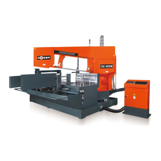
- Page 1 COSEN SAWS CNC-800DM CNC Programmable Automatic Double Miter-Cutting Horizontal Bandsaw Instruction Manual The Pinnacle of Cutting Performance Cosen Mechatronics Co., Ltd.
- Page 2 ...
- Page 3 FROM THE MANUFACTURER Thank you for your purchase of COSEN’s bandsaw machine and your trust in the COSEN brand. We are excited to have you as our valued customer and look forward as much as you do to the accelerated productivity, long-lasting endurance and superb cost-effectiveness this machine is about to bring to you.
- Page 5 Safety rules Make sure your work area is cleared of uninvited people and obstacles every time before you start operating the machine. Never step or stand on the roller table. Your foot may slip or trip on the rollers and you will fall.
- Page 6 Safety rules Never adjust the wire brush or remove chips while the saw blade is still running. It is extremely dangerous if hands or clothing are caught by the running blade. Stop the saw blade before you clean the machine. It is dangerous if hands or clothing are caught by the running blade.
-
Page 7: Table Of Contents
Table of Contents Safety Information Section 1 – Safety Instructions …………………………………………………………………………………………………….. 1-1 Safeguard Devices ……………………………………………………………………………………………………… 1-3 Emergency Stop ………………………………………………………………………………………………………… 1-4 Illustration: Emergency Stop ……………………………………………………………………………………… Safety Labels …………………………………………………………………………………………………………….. 1-6 Illustration: Safety Labels ………………………………………………………………………………………..… Hearing Protection …………………………………………………………………………………………………….. 1-10 CE Compliance ………………………………………………………………………………………………………….. 1-10 Risk Assessment ……………………………………………………………………………………………………….. - Page 8 Table of Contents Control Buttons ……………………………………………………………………………………….…… 4-5 Human‐machine‐interface (HMI) touch screen……………………………………….………. 4-7 Main control menu……………………..……………………………………………………….………… 4-8 Remote Control ………………………………………………………………………………………………………….. 4-37 HMI Error Codes ………………………..……………………………………………………….………………………. 4-38 Replacing PLC Battery …………………………………………………………………………………………………. 4-41 Standard Accessories ………….………………………..……………………………………………….………….. 4-41 Optional Accessories …….…….………………………..…………………………………………….…………….. 4-44 Manual Cutting …………………………………………………………………………………………………………… 4-47 Automatic Cutting ……………………………………………………………………………………………………….
- Page 9 Table of Contents Terminating the Use of Machine ……..…………..………………………………………………………….. Oil Recommendation for Maintenance …………………………………………………………………….. 8-4 Troubleshooting Section 9 – Introduction ……………………….…….…………………..………………………………………………………….. 9-1 Precautions ………………….…………………..……………………………………………………………………..9-2 General Troubles & Solutions ………………………..………………………………………………………….. 9-2 Minor Troubles & Solutions ………………………..………………………………………………..………….. 9-3 Motor Troubles & Solutions ………………………..…………………………………………………..……….. 9-3 Blade Troubles &...
-
Page 11: Safety Information
Safety is a combination of a well-designed machine, operator’s knowledge about the machine and alertness at all times. COSEN’s band machine has incorporated many safety measures during the design process and used protective devices to prevent personal injuries and potential risks. Warning labels also serve as a reminder to the operator. - Page 12 This manual has important safety Wear proper apparel during operation information. Read through it carefully and when servicing the machine. Some before operating this machine to personal protective equipment is prevent personal injury or machine required for the safe use of the machine, damage.
-
Page 13: Safeguard Devices
SAFEGUARD DEVICES The safeguard devices incorporated in this machine include the following two main parts: 1. Protection covers & guards 2. Safety-related switches Protection Covers & Guards 1. Idle wheel housing cover 2. Drive wheel housing cover 3. Gear reducer cover 4. - Page 14 Illustration: Safety Fence Safety Fences...
-
Page 15: Emergency Stop
Safety Related Switches To protect the operator, the following safety related switches on the machine are actuated when the machine is in operation. Wheel motion detector This is a proximity sensor used to detect the motion of the drive wheel. Once the saw blade is broken as soon as it starts slipping, the sensor will detect and stop the drive wheel and the machine. -
Page 16: Illustration: Emergency Stop
Illustration: Emergency Stop Emergency Stop Emergency Stop Emergency Stop Emergency Stop... -
Page 17: Safety Labels
SAFETY LABELS Please read through and understand these safety labels before operating the machine. Refer to Illustration: Safety Labels. Label Meaning Label Meaning Impact Hazard Read Operator’s Manual WEAR SAFETY SHOES. Do This manual has important safety not approach dropping area information. -
Page 18: Illustration: Safety Labels
Illustration: Safety Labels... -
Page 19: Hearing Protection
If maintenance does not seem to solve the problem, follow the troubleshooting procedures under Section 7. CE COMPLIANCE Cosen’s CE model is designed to satisfy regulations of the Council Directive on the approximation of the laws of the Member States relating to machinery (2006/42/EC) - Annex I Essential health and safety requirements relating to the design and construction of machinery. -
Page 21: General Information
INFORMATION SPECIFICATION MACHINE PARTS IDENTIFICATION FLOOR PLAN This band saw machine is designed by Cosen’s R&D engineers to provide you the following features and advantages: Safety This machine is designed to fully protect the operator from its moving parts during cutting operation. - Page 22 SPECIFICATION CNC-800DM Model CNC Programmable Automatic Machine Type Double Miter-Cutting Horizontal Band Saw +45° ~ -60° Miter Degree 500 mm (20 in.) 0° Round 400 x 800 mm (16 x 31 in.) 0° Rectangular (H x W) ±45° Round 450 mm (17.7 in.) Capacity ±45°...
- Page 23 MACHINE PARTS IDENTIFICATION...
-
Page 24: Floor Plan
FLOOR PLAN Machine top view... - Page 25 Machine front view Machine side view...
-
Page 27: Moving & Installation
Section 3 MOVING & INSTALLATION LOCATION & ENVIRONMENT UNPACKING & INSPECTING LIFTING REMOVING SHIPPING BRACKET CLEANING INSTALLING RELOCATING LOCATION & ENVIRONMENT For your safety, please read all information regarding installation before proceeding. Install your machine in a place satisfying all of the following conditions: Space: ... -
Page 28: Unpacking & Inspecting
UNPACKING & INSPECTING Unpack your machine carefully to avoid damage to machine parts or surfaces. Upon arrival of your new band saw, please confirm that your machine is the correct model and it comes in the same specification you ordered by checking the model plate on the machine base. ... -
Page 29: Lifting
LIFTING When moving the machine, we strongly suggest you choose any one of the methods described below to move your machine. Use a crane (Only applies to the machine with the design of the hanging point.) Move the machine to its location by using a crane and a wire rope sling that can fully withstand the weight of the machine (refer to machine specification under Section 2 General Information). - Page 30 When you work together with more than two people, it is best to keep constant verbal communication with each other. Use a forklift (Only applies to the machine with the design of the lifting point.) Make sure that the lifting rod can fully withstand the weight of the machine. (Refer to Section 2 – General Information for Specifications.) Machine lifting with a forklift should be done strictly according to the lifting points designated by the original manufacturer.
-
Page 31: Illustration: Lifting Points
3. Use rolling cylinders You can use rolling cylinders to move your machine in a small machine shop environment. You must use rolling cylinders made in material of proper compressive strength. 4. Other ways to move If the machine does not have stickers, please contact your local agent immediately. -
Page 32: Removing Shipping Bracket
Do not remove the rust-preventive grease with a metal scraper and do not wipe the painted surfaces with solvent as doing so would damage surface paint. INSTALLING Cosen’s bandsaw machine is relatively easy to install. Follow these six easy steps to install your machine. Connect Leveling &... -
Page 33: Supplying Coolant
Have a qualified electrician make the electrical connections. If the power supply voltage is different from the transformer and motor connection voltage shown on the label attached to the electrical compartment of the machine, contact COSEN or your agent immediately. -
Page 34: Leveling
Turn off the shop circuit breaker. Make sure the machine circuit breaker switch on the electrical compartment door is turned to OFF. Remove the screw securing the electrical compartment and then open the door. Pull the power supply cable and grounding conductor through the power supply inlet into the electrical compartment. -
Page 35: Installing Roller Table (Optional)
Anchoring Normally there is no need to anchor the machine. If the machine is likely to vibrate, fix the machine to the floor with anchor bolts. Shock absorption steel plates are provided and can be placed under each leveling bolt to prevent their sinking into the concrete floor. -
Page 37: Operating Instructions
Section 4 OPERATING INSTRUCTION SAFETY PRECAUTIONS BEFORE OPERATING CONTROL PANEL REMOTE CONTROL REPLACING PLC BATTERY STANDARD ACCESSORIES OPTIONAL ACCESSORIES MANUAL CUTTING AUTOMATIC CUTTING UNROLLING & INSTALLING THE BLADE ADJUSTING WIRE BRUSH ADJUSTING BLADE SPEED ADJUSTING COOLANT FLOW BREAKING‐IN THE BLADE TEST‐RUNNING THE MACHINE TERMINATING A CUTTING OPERATION 4‐1 ... -
Page 38: Safety Precautions
SAFETY PRECAUTIONS For your safety, please read and understand the instruction manual before you operate the machine. The operator should always follow these safety guidelines: The machine should only be used for its designated purpose. Do not wear gloves, neckties, jewelry or loose clothing/hair while operating the machine. For eye protection, always wear protective safety glasses. Check the blade tension and adjust blade guides before starting the machine. Use auxiliary clamping or supporting devices to fix material in place before cutting long workpieces. Always make sure the material is clamped firmly in place before starting to cut. Do not remove jammed or cut‐off pieces until the blade has come to a full stop. Keep fingers away from the path of the blade. Protection devices should be in place at all times. For your own safety, never remove these devices. Disconnect machine from the power source before making repairs or adjustments. Wear protection gloves only when changing the blade. Do not operate the machine while under the influence of drugs, alcohol or medication. Do not take your eyes off the machine while in operation. Do place warning signs to mark out machine work zone and restrict entry to be staff‐only. 4‐2 ... -
Page 39: Before Operating
BEFORE OPERATING Choosing an appropriate saw blade and using the right cutting method is essential to your cutting efficiency and safety. Select a suitable saw blade and cutting method based on your work material and job requirements e.g. cutting accuracy, cutting speed, economic concern, and safety control. Wet cutting If you choose dry cutting or low‐speed cutting, the chips may accumulate in machine parts and may cause operation failure or insulation malfunction. We suggest you choose wet cutting to avoid machine damage. Cutting unknown materials Before cutting an unknown material, consult the material supplier, burn a small amount of chips from the material in a safe place, or follow any other procedure to check if the material is flammable. Never take your eyes off the machine while in operation. Cutting fluid For cooling and lubrication purpose, we recommend you use water‐soluble cutting fluids. The following table lists out its pros and cons for your reference. Pro Con Have a high cooling effect Remove machine paint Not flammable Lose its rust protection effect if Economical deteriorated Does not require cleaning of the cut Tend to create foam Subject to decay products ... -
Page 40: Control Panel
CONTROL PANEL The control panel is located on the top of the electrical box. It includes the following function: power system, hydraulic system, cooling system and the human‐machine‐interface (HMI). The operator must fully understand the function of each switch and button before operating the machine. No. Name No. Name 1 Power indicator lamp 8 Front vise open button 2 Emergency stop button 9 Front vise clamp button 3 Saw blade start/stop buttons 10 Front movable vise backward button 4 Saw bow up (cutting stop) button 11 Front movable vise forward button 5 Saw bow down button 12 Shuttle bed – feed backward button 6 Rear vise open button 13 Shuttle bed – feed forward button 7 Rear vise clamp button 14 USB port (for flash disk/memory stick) ... -
Page 41: Control Buttons
Control Buttons 1. Power indicator lamp When the lamp is on, it indicates the power to the machine is turned on. 2. Emergency stop button Press this button to stop the machine in an emergency. When the button is pressed, it brings the machine to a full stop. The button locks when pressed. In order to unlock it, please turn the button clockwise. 3. Saw blade start/stop buttons Press green button to start cutting when the material is ready to cut; press red button to stop cutting. After the saw blade starts, the blade will come down at first quick then the preset downfeed speed: Quick approach speed Used in order to save operation time. The machine will calculate the quick approach height by the preset material shape( rectangle or round) in HMI, then the saw bow descends at a quicker speed reaching the quick approach height. See more info in Material shape in HMI section. Downfeed speed When the blade leaves the quick approach height, the saw bow will slow to come down at the downfeed speed as preset in HMI. Before pressing saw blade start button, please make sure the material shape is chosen correctly. Failure to do so might cause material not cut through and blade or material damage. After the blade motor starts running, the forward/backward functions of front and rear vises are disabled due to safety concerns. During operation, do not approach front bed where dropping might occur . 4. Saw bow up (cutting stop) button When this button is pressed, the saw bow rises until the operator lets go of the button or until the saw bow touches the upper limit switch. While pressing the saw bow up button can stop the running blade, please still use the emergency stop button in an emergency. ... - Page 42 5. Saw bow down button When this button is pressed, the saw bow descends. This machine incorporates a blade descend clearance check feature to control and ensure the blade can be lowered only when it is safe to do so. For more information, refer to HMI control panel in later section. The blade comes down at first quick then the preset downfeed speed. Please refer to supplementary notes previously explained in No. 3 saw blade start button. 6. Rear vise open button This button only works when the machine is switched to manual mode. When this button is pressed, the rear vises will open until the operator lets go of the button or until the vises are fully opened. 7. Rear vise clamp button This button only works when the machine is switched to manual mode. When this button is pressed, the rear vises will close until the operator lets go of the button or until the vises are fully closed. Rear vise cannot clamp the inclined plane of the material, or it might damage the machine. Therefore material end cannot be an inclined plane. 8. Front vise open button This button only works when the machine is switched to manual mode. When this button is pressed, the front vises will open until the operator lets go of the button or until the vises are fully opened. If the saw bow is not at the upper limit switch position, the front vise can only be opened in small increments, so as to prevent the vise from hitting the guide arm. 9. Front vise clamp button This button only works when the machine is switched to manual mode. When this button is pressed, the front vises will close until the operator lets go of the button or until the vises are fully closed. Front vise cannot clamp the inclined plane of the material, or it might damage the machine. Therefore material end annot be an inclined plane. 10. Front movable vise backward button Front vise moves backward when this button is pressed. This button is enabled only when the saw bow is at its top most position. 4‐6 ...
-
Page 43: Human-Machine-Interface (Hmi) Touch Screen
11. Front movable vise forward button Front vise moves forward when this button is pressed. This button is enabled only when the saw bow is at its top most position. 12. Shuttle bed – feed backward button When this button is pressed, the shuttle bed (shuttle vise) will move backward. Press and hold the button to feed backward. As soon as the button is released, the shuttle bed will stop moving backward. This button only works when the machine is switched to manual mode. This button is only in function when the saw bow is at its top most position AND when the front and rear vises are NOT clamped simultaneously. Before moving the shuttle vise backward, open the shuttle vise wider than the material to avoide collision. 13. Shuttle bed – feed forward button When this button is pressed, the shuttle bed (shuttle vise) will move forward. Press and hold the button to feed forward. As soon as the button is released, the shuttle bed will stop moving forward. This button only work when the machine is switched manual mode. This button is only in function when the saw bow is at its top most position AND when the front and rear vises are NOT clamped simultaneously. Before moving the shuttle vise forward, open the shuttle vise wider than the material to avoide collision. When moving forward the shuttle vise clamped with the material, pay attention not to hit the front vise. 14. USB port (for flash disk/memory stick) Human‐machine‐interface (HMI) touch screen This HMI touch screen displays operation messages so that the operator is able to understand the system condition. It also provides different operating modes and selections for the operator to work with. During a cutting job, the operator can still enter the system and make changes to the cutting operation as needed. 4‐7 ... -
Page 44: Main Control Menu
Do not wipe or clean the screen with volatile solvents. Do not overexert pressure on the screen. The touch screen is very sensitive; all buttons on the screen just need a slight touch to operate. All range parameters in Advantech 10” are configured under the “manual” mode. Please pay attention to the following environment conditions necessary for Advantech 10” HMI touch screen to properly operate: Item Range Ambient temperature 5℃ ~ 50℃ Temperature for safe operation ‐10℃ ~ 60℃ Ambient humidity 30%~85% RH (No condensation) Connection RS422 MMI port Environment No condensation and rust Startup Screen After the power is turned on, Cosen’s logo will appear as the startup screen, followed by the main operation menu.. Main control menu The main control menu includes some operating button that were used on the control panel of the earlier machines. Some convenient functions are added to the page for the operator to better understand the features of the machine. Setting the parameters shown on the screen requires a gentle touch of the finger. You can also look up the parameters or make changes while in the middle of a cut. 4‐8 ... - Page 45 Refer to the table below for descriptions of each function. No Item Function Description Hydraulic start When the power is turned on, press 1 this button to start the hydraulic motor. A sold yellow icon indicates the hydraulic system has been turned on. Hydraulic stop Press this button to turn off the 2 hydraulic motor immediately. When the blade is running, the hydraulic stop button is temporarily disabled. You need to press the saw bow up button or the emergency stop button to stop the blade. AUTO/Manual mode Use this button to switch between 3 automatic and manual mode. AUTO mode ( ): used to automatically perform continuous cutting steps. When switched to the AUTO mode, ...
- Page 46 No Item Function Description step. When switched to the Manual mode, you can execute each individual function. Coolant ON/OFF Press this button to turn on the 4 coolant pump. A solid yellow faucet icon indicates the coolant pump has been turned on. Press again to turn off the coolant pump. Under automatic mode, a started blade will also start the coolant. Carbide inserts clamp/unclamp When under manual mode, press this 5 button to clamp carbide inserts. Press again to unclamp. The carbide inserts are programmed to automatically clamp when the saw blade starts in order to protect the blade and the user. Projection light ON/OFF Press this button to turn on the 6 projection light. A solid yellow light bulb icon indicates the projection light has been turned on. Press again to turn off the projection ...
- Page 47 No Item Function Description Automatic cutting mode selection When under manual mode, press this 9 button to open the window to choose from three automatic cutting modes: loop multiple angle mode, NC100 single angle mode, and NC100 multiple angle mode. See Cutting Mode Setting & Selecting in later section. Saw bow automatically swivel When under manual mode, press this 10 button to open the automatically swivel window for adjusting mitering angle. See Auto Swivel in later section. PLEASE STAY OUT OF SWIVELING AREA OR SEVERE INJURY OR DEATH MAY OCCUR! Guide arm automatic positioning Press this button to turn on the guide 11 function ON/OFF arm automatic positioning function when under manual mode. With this function, the guide arm automatically moves in sync with the swiveling saw bow and positions itself at the best possible location based on the mitering angle. Guide arm to the LEFT Press this button to move the guide ...
- Page 48 No Item Function Description angle (shown on the HMI touch screen). This button only works when the following conditions are both met: When the machine is switched to manual mode. When the saw frame is raised to its upper most position i.e. when the saw bow upper limit switch is activated. Saw head swivel backward (clockwise) When this button is pressed, the saw 16 head will start swiveling backward i.e. clockwise until the button is released or until reaching the maximum “‐ “ mitering capacity, 60°. Press the button and release it when arriving at your desired mitering angle (shown on the HMI touch screen). This button only works when the following conditions are both met: When the machine is switched to manual mode. When the saw frame is raised to its upper most position i.e. when the saw bow upper limit switch is activated. ...
- Page 49 No Item Function Description to enter its setting page. See Cutting Mode Setting in later section. Material cutting reference This 3‐page reference chart lists out 20 the required blade speed and cutting rate for each different material. Press Home to return to the main control menu. Press Page Down to go to the next page. PLC signal monitor This page shows current PLC signals. 21 Press Home to return to the main control menu. Error report Lists a historical report of the errors 22 and the time of occurrence as well as provides troubleshooting support. Press Home to return to the main control menu. ...
- Page 50 No Item Function Description clearance status. Press Home to return to the main control 2. Clearance indicator: Green light on: Indicates that saw bow is cleared and allowed to descend. Red light on: Indicates that saw bow is not allowed to descend due to clearance problem. ROUND/RECTANGLE work cutting To save operation time, this machine 26 incorporates a program which designates different quick approach height for round and rectangle work of different width. The blade will descend quickly to programmed quick approach height to save blade running time. When cutting rectangle shaped material such as I‐beam, profiles and etc., be sure to switch to rectangle work cutting or the material might not be cut through and material and blade might damage. Front vise automatic positioning ...
- Page 51 No Item Function Description Back (‐) 90.2°~ 96° Front limit Position 2 Back (‐) Front middle Position 4 96.1°~ 150° limit The blade will not start if the front movable vise is not at its required position. For better results, have the front vise automatic positioning function ON all the time. Shuttle vises feed speed FAST/SLOW Press this button to switch the 28 shuttle vise feed speed between fast (rabbit icon) and slow (snail icon). Shuttle vise position indicator Indicates the position of the shuttle vises: whether they have reached the front limit switch. When the shuttle vises have reached the front limit switch position, the shuttle vise icon at the front will turn solid white. Front/Rear vises status indicators When the vises have secured the 29 work piece, the clamping vise icon on the right will turn solid white. ...
- Page 52 No Item Function Description When the blade completes each cut and triggers the lower limit switch, the saw blade icon will turn solid white. Shuttle vise position / feed length Displays current position of the 32 display shuttle vise, which also indicates the length to be fed. Shuttle vise multiple feed length Displays multiple feed length of the display shuttle vise. It clears when the cutting completes. Front vise opening width display Displays how wide the front vise is currently opened i.e. the horizontal distance between front movable vise and front fixed vise. Round material height is detected by the front vise opening width sensor. Saw bow height display Displays current height of the saw bow. Mitering angle display Displays current mitering angle i.e. which angle is the saw bow swiveled to. Saw bow Miter HMI Angle Direction ...
- Page 53 Main Control Menu #7 : Home Button Whenever the machine is restarted, “Home” action must be performed so that the saw bow and shuttle bed can return to zero position. Otherwise the saw bow would not come down and shuttle vise can only move in jog mode. Follow these steps to perform the action: Step 1 – Press the hydraulic start button . Step 2 – Switch to manual mode . Step 3 ‐ Press the home icon and the following window will appear . Step 4 – Press the home icon and the machine will perform the following “Home” action. First the saw bow will move up to the upper limit position. Then the saw bow will swivel to 45° (return‐to‐zero point of mitering angle) then 90°. Next both front and rear vises will fully open. Rear vise will move back to rear limit position as its return‐to‐zero point. Front vise will move from position 1 to 3 then back to 1 (please refer main control menu No. 26 front movable vise position). To stop the home action, press either the home icon or the saw bow up button. Step 5 – Press the close icon to close the window. Main Control Menu #9 : Cutting Mode Setting & Selecting When under manual mode, press this button to open the window to choose from three automatic cutting modes: loop multiple angle mode, NC100 single angle mode, and NC100 multiple mode. Loop multiple angle mode ( ): used when a product is formed under 4 continuously loop cutting steps. Product quantity can be counted for this mode. NC 100 single angle ( ): used when the product is formed with the same mitering angle cuttings. Product quantity can be counted for this mode. NC 100 multiple angle ( ): used for those multiple angle product which cannot be formed with loop ...
- Page 54 Step 2 – Press the auto swivel icon and the following window will appear . Step 3 – Press the icon and enter the desired mitering angle( 45°~150°). Step 4 – Press the auto swivel icon and saw bow will automatically rise to the upper limit position then swivel to preset angle. To stop the swiveling, press either the auto swivel icon or the saw bow up button. Step 5 – Press the close icon to close the window. Main Control Menu #18 : Status Display & Setting Display/Button Description Blade Speed Current blade speed display Down Feed Current downfeed speed display Feed Length Shuttle vise position / feed length display Width Front vise opening width display Height Saw bow height display Angle Mitering angle display Guide Arm Guide arm position display AMP. Blade motor current display Time Left Remaining cutting time display (in min. only) Estimated Time Estimated cutting time for current material under preset downfeed speed ...
- Page 55 Main Control Menu #19 : Cutting Mode Setting After choosing an automatic cutting mode, corresponding mode button will appear at the right most of main Refer below descriptions for the following control menu. Press the mode button to enter its setting page. automatic cutting mode: loop multiple angle mode, NC100 single angle mode and NC100 multiple angle mode. Loop multiple angle mode The Cutting Job Setting and Selecting Page is divided into two work zones: Effective Job and Standby Job. Effective Job Zone is where the cutting job in action can be monitored, re‐edited and used for re‐work. Standby Job Zone is where cutting data can be retrieved from database or external memory for users to start preparing for the next cutting job. Effective Job Work Zone E1: Job Info Display/Button Description Job No. Job number in effect Job Name Name of the job in effect. For job naming, refer to Job Database in later section. Job Notes ...
- Page 56 E2: Job Step Info Display & Re‐Program (1) Display/Button Description Step No. Lists out the steps programmed in the effective job. Each job can include up to four cutting steps. Blade Speed Displays the preset blade speed for each given step. Blade speed can be reprogrammed by directly pressing the number icon and entering a new speed. The new speed will take effect at the next time the given step is executed. Changing blade speed while the given step is being executed will not take immediate effect. If you wish to change speed of the current running blade, use the blade speed control buttons on the HMI home menu. Downfeed Displays the preset downfeed speed for each given step. speed Downfeed speed can be reprogrammed by directly pressing the number icon and entering a new speed. The new speed will take effect the next time the given step is executed. Changing blade downfeed speed while the given step is being executed will not take immediate effect. If you wish to change downfeed speed of the current running blade, use the downfeed speed control buttons on the HMI home menu. Length Displays the preset feed length for each given step to cut. Feed length can be reprogrammed by directly pressing the number icon and entering a new feed length. The new length will take effect the next time the given step is executed. Changing feed length while the given step is being executed will not take immediate effect. ...
- Page 57 E3: Job Step Info Display & Re‐Program (2) Display/Button Description Step Starts The starting step is set to be 1 at default. No change is allowed. Step Ends Displays the ending step number, which can also be reprogrammed by directly pressing the number icon. If product needs two steps to form, set step end at 2. The given example on the right means cutting starts at Step 1 and ends with Step 4. P. Qty Displays the quantity of cut‐off work the user wishes to produce. The quantity can be reprogrammed by directly pressing the number icon and entering a new product quantity. Changing the product quantity during automatic cutting is allowed. Once it is changed, the machine will continue to cut until reaching the new product quantity. If the new quantity is smaller than the finished quantity, the machine will stop right after completing the cut. E4: Product Count Formula Display & Re‐Program Display/Button Description Product Count Displays the formula number chosen for the effective job. Formula In this example, the formula number is 41. Set Press this button to enter the Product Count Formula Selection page, where the user can choose a calculation formula for product count. (See explanations on Selecting Product Count Formula in later section.) Formula Icon Displays the corresponding formula graphic for the formula chosen. In this example, the formula graphic ...
- Page 58 Two examples listed below provides a step‐by‐step explanation of how the product quantity is counted with the formula step sequence looks for matching numbers from below while the completed step sequence enters from right to left and moves from slot to slot as each cutting step completes. Sequence Example: Formula 21 Sequence Example: Formula 24 Starting Formula Step Starting Formula Step 0 0 0 1 2 0 0 1 2 1 step 1 step 1 Completed Step Completed Step 0 0 0 0 0 1 0 0 0 0 0 1 Starting Formula Step ...
- Page 59 E8: Trim Cut Selecting Press Trim Cut icon and selecting window will pop out. This machine incorporats a 90° leading edge ( ) locater function. It cannot locate non 90° leading edge. If this function is desired but leading edge is not 90°, cut the leading edge as 90°first. If the material head is an incline plane, locating leading edge might cause front vise clamping the incline plane and damage the machine. Before locating the leading edge, put the material in between rear vise and edge locater sensor, about 400mm extending from the rear vise. Display/Button Description No Trim Cut Indicates trim cut is not needed. Before cutting, both front and rear vises need to be clamped. Either one not clamped might cause damage to the machine. After starting the blade, in order to avoid “‐ “ angle cutting causes front vise clamping the incline plane, machine will release the front vise automatically. Leading Edge Indicates locating material leading edge is needed and Locater (90°) current step angle is 90°. After machine has located the edge, current step is seen completed. Therefore the current step angle must be 90° or the cutting will not start. Before cutting, rear vises need to be clamped and saw bow needs to be at upper limit position. Trim Cut With Indicates locating material leading edge is needed and Angle current step angle is NOT 90°. ...
- Page 60 Standby Job Work Zone S1: Standby Job Info Display/Button Description Job No. All the standby job information listed on the left are retrieved Job Name from the job database. As they are displays only, no editing is Job Notes allowed in this work zone. For explanations, please refer to Step No. Effective Job Work Zone: E1~E4 from earlier sections. Blade Speed Downfeed Speed Standby Job Zone is where cutting data can be retrieved Length from database or external memory for users to start Angle preparing for the next cutting job. Step Starts Step Ends Product Quantity Product Count Formula S2: Enter JOB Database Page Display/Button Description Enter JOB Press this button to enter the JOB database page, where data of a Database total of 500 cutting jobs can be loaded from external memory, reprogrammed, and saved. The selected cutting job then will be displayed in the Standby Job work zone as previously introduced. See JOB Database Page for more information. S3: Standby Job Info Display/Button ...
- Page 61 D1: Cutting Jobs in Database This window lists out the cutting jobs stored in the database. To recall a cutting job, use D2 buttons to quickly jump to other jobs. Display/Button Description Job No. Job number Job Name Name of the job Job Notes Supplementary notes about the job D2: Jumping to & Recalling A Cutting Job Use these convenient buttons to jump to and recall a certain cutting job. Display/Button Description Job No. Press the number icon and directly enter the job number to jump to. +20 Jump ahead 20 jobs. +10 Jump ahead 10 jobs. +1 Jump to the next cutting job. ‐1 Jump back to previous cutting job. ‐10 Jump backward 10 jobs. ‐20 Jump backward 20 jobs. D3: Editing the Standby Cutting Job (1) Display/Button Description Job No. Displays the job number recalled for standby work zone Job Name Displays the name of the job recalled for standby work ...
- Page 62 feeding for the first cut of the first step. The saw will cut where material is fed and clamped at. Angle Displays the preset mitering angle for each given step. Angle can be reprogrammed by directly pressing the number icon and entering a new angle. D5: Editing the Standby Cutting Job (3) Display/Button Description Product Count Displays the formula number chosen for the effective job. Formula In this example, the formula number is 41. Set Press this button to enter the Product Count Formula Selection page, where the user can choose a calculation formula for product count. (See explanations on Product Count Formula Selection in later section.) Formula Icon Displays the corresponding formula graphic for the formula chosen. In this example, the formula graphic corresponds to formula number 41. P. Qty (Product Displays the quantity of cut‐off work the user wishes to Quantity) produce. The quantity can be reprogrammed by directly pressing the number icon and entering a new product quantity. D6: Loading Data from Memory Display/Button Description Open File Press this button to open a cutting job file from internal or external memory drive. When a dialogue box pops out, select the file you wish to load data from. At default, the job database automatically reloads a default ...
- Page 63 Default memory Disk D for Micro SD plugged into HMI drive system at time of manufacture Optional Disk E for optional memory stick memory drive (flash drive) connected to the USB socket on the control panel As the job database automatically reloads data from Disk D each time upon machine restart, it is important to save your work before turning off the machine. D8: Return to Cutting Job Setting & Selecting Page Display/Button Description Page Up Press this button to return to the cutting job setting and selecting page. The cutting job recalled will be shown in the standby cutting job section. Selecting Product Count Formula 1 Select a job type. Based on the number of steps your cutting job includes, select the corresponding job type. For example, press anywhere within the bracket which writes “For a 4‐step job” if you wish to execute a four‐step job, then a list of option on calculation formula will pop out. 2 Select a formula from the options provided. From the options provided, select the desired calculation formula and press the corresponding formula number key. The green light will come on for ...
- Page 64 Calculation Formula Options Choosing the calculation formula right is important to getting a correct product count. An example is provided below to explain the concept of cutting step, cutting sequence and the different ways of producing a cutoff product. Example: Step Setting Step starts = Step Angle Feed Length Step ends = 1 120° 200 mm P. Qty = 2 50 mm 60° Cutting Sequence (illustrated) Calculation Formula No: Formula Representing formula graphic: Numbers inside the circle represents step number. A circle represents a finished product. Explanation in detail: In the first (green) circle, it requires the completion of three steps i.e. step 1, step 2 and then step 1 in order to account for one finished product. (As shown in cutting sequence illustrated above, it takes ...
- Page 65 Formula No. Formula For a Graphic 1‐step Formula Cut 1 Starting step 1 Formula Step 0 0 0 0 1 Step Completed Step 0 0 0 0 0 1 Step 1 ends Formula Step P.Qty = 1 0 0 0 0 1 Completed Step 0 0 0 0 1 ...
- Page 66 Example Cutting Sequence Formula No. Formula Graphic Formula Cut 1 Starting step 1 Formula Step 0 0 0 2 1 Step Completed Step 0 0 0 0 0 1 Cut 2 Starting step 2 Formula Step 0 0 0 1 2 Completed Step 0 0 0 0 1 2 ...
- Page 67 Example Cutting Sequence Formula No. Formula For a Graphic 3‐step Formula Cut 1 Starting step 1 Formula Step 0 0 1 2 3 Step Completed Step 0 0 0 0 0 1 Cut 2 Starting step 2 Formula Step 0 0 1 2 3 ...
- Page 68 Example Cutting Sequence Formula No. Formula For a Graphic 4‐step Formula Cut 1 Starting step 1 Formula Step 0 1 2 3 4 Step Completed Step 0 0 0 0 0 1 Cut 2 Starting step 2 Formula Step 0 1 2 3 4 ...
- Page 69 Formula No. Formula Graphic Formula Cut 1 Starting step 1 Formula Step 1 2 3 4 1 Step Completed Step 0 0 0 0 0 1 Cut 2 Starting step 2 Formula Step 1 2 3 4 1 Completed Step 0 0 0 0 1 2 Cut 3 ...
- Page 70 Display/Button Description Job Job number Length Set the feed length for each given job to cut. Feed length can be reprogrammed by directly pressing the number icon and entering a new length. P. Qty Set the quantity of cut‐off work the user wishes to produce. The quantity can be reprogrammed by directly pressing the number icon and entering a new product quantity. F. Qty Displays the current quantity of finished product. Job Starts Press the number icon and enter which job to start with. When current job is done, it will automatically jump to next job number. Job Ends Press the number icon and enter which job to end with. Trim Cut Selecting Press this icon to select trim cut mode. Please refer below detail. Clear Cut Press this icon for three seconds to clear all the F. QTY. All Reset Press this icon for three seconds to clear all the setting. Home Press this icon to go back to the main control menu. 00~09 Cutting job setting page switch. Total 100 setting jobs (00~99). Cutting job 01~04 setting is shared by loop multi angle mode, NC100 single angle mode, and NC100 multi angle mode. Cutting job 00, 05~99 setting is shared by NC100 single angle mode, and NC100 multi angle mode. ...
- Page 71 one. Therefore the current step angle must be 90° or the cutting will not start. Before cutting, rear vises need to be clamped and saw bow needs to be at upper limit position. Trim Cut With Indicates locating material leading edge is needed and Angle current step angle is NOT 90°. After machine has located the edge, machine will swivel to trim cut angle, feed the trim cut length (press and enter) then trim cut. When trim cut is done, cut piece is not yet a product. The machine continues to feed the first length and start cutting. When the cutting is done, the first product is formed and product count adds by one. Trim cut angle Trimming length position “+” angle “‐“ angle Before cutting, rear vises need to be clamped and saw bow needs to be at upper limit position. NC100 multi angle mode Display/Button Description Job Job number Blade Speed Set the blade speed for each given job to cut. Blade speed can be reprogrammed by directly pressing the number icon and entering a new speed. Downfeed ...
- Page 72 Speed descend speed can be reprogrammed by directly pressing the number icon and entering a new speed. Length Set the feed length for each given job to cut. Feed length can be reprogrammed by directly pressing the number icon and entering a new length. Angle Set the miter angle for each given job to cut. Miter angle can be reprogrammed by directly pressing the number icon and entering a new angle. P. Qty Set the CUT NUMBER the user wishes to produce. The number can be reprogrammed by directly pressing the number icon and entering a new number. F. Qty Displays the current number of finished CUT. Job Starts Press the number icon and enter which job to start with. When current job is done, it will automatically jump to next job number. Job Ends Press the number icon and enter which job to end with. Trim Cut Selecting Press this icon to select trim cut mode. Please refer below detail. Clear Cut Press this icon for three seconds to clear all the F. QTY. All Reset Press this icon for three seconds to clear all the setting. Home Press this icon to go back to the main control menu. 00~09 Cutting job setting page switch. Total 100 setting jobs (00~99). Trim Cut Selecting Press Trim Cut icon and selecting window will pop out.
-
Page 73: Remote Control
Trim Cut With Indicates locating material leading edge is needed and Angle current step angle is NOT 90°. After machine has located the edge, machine will swivel to trim cut angle, feed the trim cut length (press and enter) then trim cut. When trim cut is done, current step is seen completed and cut count adds by one. Trim cut angle Trimming length position “+” angle “‐“ angle Before cutting, rear vises need to be clamped and saw bow needs to be at upper limit position. Remote Control (optional) The remote control is only in fuction when the saw bow is at the upper limit switch position AND BOTH front and rear vises are not clamping the material. Symbol Switch Description No use 3M powered roller table clutch ON 3M powered roller table clutch OFF 3M powered roller fast feeding mode 3M powered roller slow feeding mode 3M powered roller feeding forward 3M powered roller feeding backward 4‐37 ... - Page 74 Error Error Description Further Description/Solution Code M300 Front vises not clamped Check if the queen valve works M301 Rear vises not clamped Check if the queen valve works M303 Lower limit switch error Check if the lower limit switch works M304 Hydraulic motor not starting Check if the hydraulic motor works M305 Both front and rear vise clamped Both front and rear vises are clamped and rear vises cannot move. M306 Broken blade detected 1. Check if the speed switch works 2. Check if the blade is broken M308 Left safety door abnormal 1. Check if the left safety door is shut properly 2. Check if the left safety door limit switch works M309 Right safety door abnormal 1. Check if the right safety door is hut properly 2. Check if the right safety door limit switch works ...
- Page 75 Error Error Description Solution Code M330 Time‐out: front vise to position 1 Check if front vise moves normally (rear) M331 Time‐out: front vise to position 2 Check if front vise moves normally (front) M332 Time‐out: front vise to position 3 Check if front vise moves normally (second to rear) M333 Time‐out: front vise to position 4 Check if front vise moves normally (second to front) M334 PLC battery low voltage The battery will soon be out of battery. It is critical to replace the battery, otherwise all programs and system parameters will be lost and the machine will not be able to function. Follow the below steps to replace battery. M335 Guide arm not synchronized: Activate guide arm automatic positioning function. please activate M336 Front vise not synchronized: please Activate front vise automatic positioning function activate M337 Servo motor: zero return Require servo motor zero return procedure after procedure required restarting the machine ...
- Page 76 Error Error Description Solution Code M352 Front vise clamping abnormal 1. Place new material 2. Check if the vise queen valve works 3.Check if the “no material parameter” is too low M353 Rear vise clamping abnormal Check if the vise queen valve works M354 Shuttle vise forward‐feed abnormal Shuttle vise forward‐feed time out. Check if shuttle vise move forward normally. M355 Shuttle vise reverse‐feed abnormal Shuttle vise reverse‐feed time out. Check if shuttle vise move backward normally. M356 Saw blade slipping Saw blade broken or slipping M357 Saw bow descend abnormal 1. Check if the descend solenoid valve is stuck 2. Check the quick approach bar works 3. Check if the quick approach bar limit switch works M358 Saw bow ascend abnormal 1. Check if the ascend solenoid valve is stuck 2. Check the quick approach bar works 3. Check the quick approach bar limit switch works M361 No material 1. Place new material 2. Check if the vise queen valve works 3.Check if the “no material parameter” is too low M362 Hydraulics stopped due to last cut Hydraulic system automatically stop due to last cut ...
-
Page 77: Replacing Plc Battery
REPLACING PLC BATTERY STANDARD ACCESSORIES Blade tension device This blade tension device equipped with hydraulic cylinder provides appropriate tension to the saw blade. To tighten the saw blade, turn the selector to . Upon saw blade breakage, the safety device will activate and automatically stop all machine operation. To change the blade, turn the handle to to release saw blade tension. 4‐41 ... - Page 78 Never adjust blade tension while the blade is running. Blade speed/motion detector Besides detecting the blade speed, the speed/motion detector also functions as a safety device. The speed/motion detector protects operators and the machine by preventing blade overloads and consequent damages if a saw blade breaks or skids. Once blade breakage or slippage is detected, the drive wheel will stop in 10 seconds. Inverter This inverter is installed inside the machine base. It is used to control and stabilize the saw blade speed during cutting. To adjust blade speed, use the blade speed control knob on the control panel. Voltage used should not exceed AC 460V. Note: 1. Make sure the terminal points are connected. 2. Make sure the ambient temperature is within acceptable range and keep the surroundings well ventilated. 3. Keep the inverter away from dust. 4. For repair or maintenance, please contact your local agent. Gear reducer The specially designed gear reducer can work toward your preset blade ...
- Page 79 Wire Brush The wire brush is hydraulically driven to rotate at the same speed as the blade motor. It removes the metal chips on the saw blade teeth so that blade life can be extended. Keep hands away from the transmission shaft and the brush while the wire brush is running. Turn off the hydraulic motor or the main power switch before performing maintenance or cleaning on the wire brush drive system. Hydraulic front top clamp device The top clamp will hold the material tightly so as to avoid material sliding during cutting. Use the adjusting valve to adjust its speed during A A d d j j u u s s t t i i n n g g clamping/unclamping.
-
Page 80: Optional Accessories
Vibration Damper Vibration damper roller is installed on the left saw arm. It reduces the high frequency noise while cutting large work piece. Lubrication device This device automatically provides lubrication to the ballscrews and linear guides. OPTIONAL ACCESSORIES Vise Pressure Regulator This adjustment valve is used to control vise pressure. Adjust vise pressure based on the material of your workpiece. Pressure When cutting pipes or soft materials, reduce vise pressure to prevent exerted pressure from damaging the workpiece gauge shape or exterior. Do not adjust vise pressure at any time during cutting. Vise pressure should never be lower than 8 kg/cm Adjusting valve Chip conveyor Chip conveyor is a spiral device to bring chips out during cutting. When the hydraulic system is turned on, the user can adjust the conveying speed via the pressure valve. As a regular maintenance, remove the chip conveyor ... - Page 81 Projection Light Activate the switch to project a beam of light on the work piece. The operator can use the light as reference to adjust the cutting dimension of the work piece. The light will shut off automatically within 90 seconds. Warning Light Warning light indicates below messages: 1. Red light: any abnormal situation 2. Yellow light: Hydraulic motor is on, blade is not running and no abnormal situation 3. Green light: Blade motor is on(blade is running) and no abnormal situation 4. Flash green light: Cutting completes and no abnormal situation Blade Deviation Detector This device detects blade deviation. If the blade deviates beyond the preset range, the machine will stop automatically. When this device is installed, the cutting width will be reduced. The blade deviation detected value and preset values are displayed on the control panel screen. ydraulic rear top clamp device The top clamp will hold the material tightly so as to avoid material sliding during cutting. Use the adjusting valve to adjust its speed during clamping/unclamping.
- Page 82 Blade protection device This device is for blade protection. When electric current value is greater than default setting value, saw bow automatically rises to avoid blade damage. V‐Drive It increases cutting efficiency and reduces vibration. 2M Roller Table The optional 2M roller table supports the work material and ensures the material is fed in smoothly. 3M Powered Roller Table The 3M roller table is able to keep work pieces level with the machine and ensure the material is fed in smoothly. Please refer to Section 9 for instructions on adjusting roller tables. 4‐46 ...
-
Page 83: Manual Cutting
Power Terminal Block for 3M Powered Roller Table Situated below the workbed, this optional accessory is the power source of the 3‐meter powered roller table and is water‐proof and can be quickly installed. Do not make any changes to the terminal. Remote Control for 3M Powered Roller Table With this remote control, you can choose to operate the roller table independently or synchronize the rollers with the movement of workbed vises. You can use the remote control to feed the material both forward and backward. The feed speed selection switch also allows users to quickly and accurately feed the work pieces to the cutting area. MANUAL CUTTING Step Action 1 Switch to manual mode. 2 Turn on the auto swivel function if necessary. 3 Open front and rear vises and place material. 4 Clamp rear vises until rear clamping vise icon turns solid white. 5 Turn on the front vise automatic positioning function. 6 Clamp front vises until front clamping vise icon turns solid white. 7 Turn on the guide arm automatic positioning function. 8 Descend the saw bow just above the material. No quick approach device function under manual mode. 9 Press the saw blade start/stop switch and start the blade. ... -
Page 84: Automatic Cutting
AUTOMATIC CUTTING Step Action Reference 1 Position material Make full use of shuttle vise (refer to manual mode) forward/backward buttons to position the material where the first Step 1 Step 1 cut needs to be. Alignment point L1 L1 Front vise clamp / rear vise clamp 2 Clamp both front and rear vises (refer to manual button. mode) 3 Raise the saw bow to be at the upper limit Saw bow up button position 4 Switch to AUTO mode. 5 Program cutting job Effective Job Work Zone Standby Job Work Zone a. Make sure all required information including Job Database ... -
Page 85: Unrolling & Installing The Blade
UNROLLING & INSTALLING THE BLADE Always wear leather gloves and protection glasses when handling a blade. Unrolling the blade Please follow the procedures illustrated below. Installing a new blade Step 1 ‐ Select the most suitable saw blade for your workpiece considering the size, shape and material. Step 2 ‐ Turn on the machine power by switching to ON and turn on the hydraulic system. Step 3 ‐ Switch to manual ( ) mode. Step 4 ‐ Press the saw bow up button and elevate the saw bow to the proper position. Step 5 ‐ Turn the tension controller handle from “ ” to “ ” position to release tension. The idle wheel will then move slightly toward the direction of the drive wheel. Step 6 ‐ Open the idle and drive wheel cover. Step 7 ‐ Open the wire brush cover. Loosen the screws and move the wire brush away from the blade. Step 8 ‐ Detach the old blade from below the left and right guide seat and then pull the entire blade out. 4‐49 ... -
Page 86: Adjusting Wire Brush
Step 9 ‐ Place the new blade around the idle wheel and the drive wheel Step 10 ‐ Insert the blade into the left and right tungsten carbide inserts. The back and the sides of the blade need to be touching the inserts as well as the adjacent rollers. Step 11 ‐ Place the blade to the drive wheel and press the back of the blade against the flange of the idle/drive wheel. Turn the tension controller handle to [ ] position to obtain blade tension. Step 12 ‐ Adjust wire brush to a proper position and tighten the screws. Step 13 – Gently close the idle and drive wheel covers. ADJUSTING WIRE BRUSH Follow these steps to adjust wire brush to appropriate position: Step 1 – Open the wire brush cover. Step 2 – Loosen the screws. Step 3 – Make brush move up / down until it makes proper contact with the saw blade (see below illustration). Step 4 – Tighten the screws. Step 5 – Close the wire brush cover. Proper Improper ADJUSTING BLADE SPEED Step 1 – Set the flow control to “0” position. Step 2 – Press the saw blade start button to start the blade. Step 3 – Turn the blade speed control knob to adjust the blade speed. The blade speed should be adjusted based on the size and the material of the workpiece. 4‐50 ... -
Page 87: Adjusting Coolant Flow
ADJUSTING COOLANT FLOW Step 1 – Press the saw blade start button to start the saw blade drive motor. Step 2 – Press the saw bow down button to lower the saw bow. Step 3 – Use the flow control valve (shown below) to adjust the amount of fluid flowing to the cutting area. Coolant Flow Valve Adjust the flow amount if you observe the following changes to the chips generated from cutting. If the chips are sharp and curved, increase the coolant flow amount. If the chips are granulated, decrease the coolant flow amount. BREAKING‐IN THE BLADE When a new saw blade is used, be sure to first break in the blade before using it for actual, extended operation. Failure to break in the blade will result in less than optimum efficiency. To perform this break‐in operation, the following instructions should be followed: Step 1 ‐ Reduce the blade speed to one‐half of its normal setting. Step 2 ‐ Lengthen the cutting time to 2‐3 times of what is normally required. 2 Step 3 ‐ The complete break‐in operation requires cutting on a 645mm (25.4in ) section for 5 times. Step 4 ‐ After the break‐in operation is completed, set all parameters back to normal settings. ... -
Page 88: Test -Running The Machine
TEST‐RUNNING THE MACHINE Test‐running this machine can ensure good machine performance in the future. We suggest you run the following tests on the machine before first use: Testing machine performance: Turn on the power and run a basic performance test after you finish installing the machine. Follow these steps to test machine performance: Step 1 – Disassemble shipping brackets and bolts. Step 2 – Install roller table (optional). Step 3 – Turn on the relay switch in the control box. Step 4 – Elevate the saw bow. (If your coolant pump is in reverse and the machine cannot run, please change the electrical phase.) Step 5 – After the saw bow ascends, extend the quick approach device (optional). Step 6 – Remove the rust‐prevention grease with cleaning oil or kerosene. Step 7 – Start the coolant pump. Step 8 – Test these functions under manual mode: vise clamping/unclamping saw bow ascending/descending feeding forward and backward. STOP TERMINATING A CUTTING OPERATION • To terminate a cutting operation, press either the saw bow up button or the emergency stop button. • The saw blade will stop running when the saw bow up button is pressed. • Both the saw blade and hydraulic pump motors will stop running when the emergency stop button is pressed. The machine will stop automatically when an error occurs. The error message will be shown on the screen. 4‐52 ... -
Page 89: Electrical System
Section 5 ELECTRICAL SYSTEM ELECTRICAL CIRCUIT DIAGRAMS The following are electrical circuit diagrams of the system: Non‐CE model with the power roller table Fig. 5‐1 Control panel layout Fig. 5‐2 Circuit board layout Fig. 5‐3 Power supply layout Fig. 5‐4 PLC I/O layout Fig. 5‐5 Servo Fig. 5‐6 Remote control Non‐CE model without the power roller table Fig. 5‐7 Control panel layout Fig. 5‐8 Circuit board layout Fig. 5‐9 Power supply layout Fig. 5‐10 PLC I/O layout Fig. 5‐11 Servo 5‐1... - Page 90 Fig. 5‐1 Control panel layout 5‐2 ...
- Page 91 Fig. 5‐2 Circuit board layout 5‐3...
- Page 92 Fig. 5‐3 Power supply layout 5‐4 ...
- Page 93 Fig. 5‐4 PLC I/O layout 5‐5...
- Page 94 Fig. 5‐5 Servo 5‐6 ...
- Page 95 Fig. 5‐6 Remote control 5‐7...
- Page 96 Fig. 5‐7 Control panel layout 5‐8 ...
- Page 97 Fig. 5‐8 Circuit board layout 5‐9...
- Page 98 Fig. 5‐9 Power supply layout 5‐10 ...
- Page 99 Fig. 5‐10 PLC I/O layout 5‐11...
- Page 100 Fig. 5‐11 Servo 5‐12 ...
-
Page 101: Hydraulic System
Section 6 HYDRAULIC SYSTEM HYDRAULIC CIRCUIT DIAGRAMS 6‐1... - Page 102 Fig. 6‐1 Hydraulic circuit layout 6‐2...
- Page 103 Hydraulic parts list for CNC-800DM PART NO. PART NAME IN CHINESE PART NAME PP-43521 電磁閥 Solenoid valve 11a PP-43125 引導止回閥 Guiding check valve 11b AGB-707019G 鋸弓油壓缸組 Sawbow cylinder assembly 11c AGB-707270 濾油器組 Filter assembly PP-43601 電磁閥 Solenoid valve PP-43508 電磁閥...
- Page 104 Hydraulic parts list for CNC-800DM PART NO. PART NAME IN CHINESE PART NAME 31b PP-43468 油壓缸 Hydraulic cylinder NGG-33000-1 壓差閥組 pressure valve 34a PP-43127A 減壓閥 Pressure regulator 34b PP-43311A 壓力表 Pressure gauge PP-43525 電磁閥 Solenoid valve 35a PP-43117 流量閥 Flow vlave 35b PP-43473 油壓缸...
- Page 105 Hydraulic parts list for CNC-800DM PART NO. PART NAME IN CHINESE PART NAME 71a PP-31640-1 油壓馬達 Hydraulic motor 71b PP-43117 流量閥 Flow vlave 72a AGB-707209-1 張力油壓缸組 Tensioner cylinder assembly 72b PP-43842 手動方向閥 三位 Manual three way valve 72d PP-43311A 壓力表...
- Page 106 ...
-
Page 107: Bandsaw Cutting: A Practical Guide
Section 7 BANDSAW CUTTING: A PRACTICAL GUIDE INTRODUCTION SAW BLADE SELECTION VISE LOADING BladeBreak -In SOLUTIONS TO SAWING PROBLEMS... - Page 108 INTRODUCTION TPI: The number of teeth per inch as measured from gullet to gullet. 2. Tooth Rake Angle: The angle of the tooth face measured with respect to a line perpendicular to the cutting direction of the saw. 3.Tooth Pitch: Tooth pitch refers to the number of teeth per inch (tpi). 1 inch equates to 25.4 mm. A distinction is made between constant tooth pitches with a uniform tooth distance, 2 tpi for example, and variable tooth pitches with different tooth distances within one toothing interval.
-
Page 109: Vise Loading
4. Tooth pitch The main factor here is the contact length of the blade in the workpiece. If it is 4P, 25.4 ÷ 4 P = 6.35 mm, that is, one tooth is 6.35 mm. If it is 3P, 25.4 ÷ 3 P = 8.46 mm If the number is small, it means that the tooth is large. What is written as 3/4 is that it is a variable pitch of large (3) / small (4). -
Page 110: Bladebreak -In
The following diagrams suggest some costeffective ways of loading and fixturing. Be sure, regardless of the arrangement selected, that the work can be firmly secured to avoid damage to the machine or injury to the operator. BladeBreak -In Completing a proper break-in on a new band saw blade will dramatically increase its life. 1. -
Page 111: Maintenance & Service
Section 8 MAINTENANCE & SERVICE INTRODUCTION BASIC MAINTENANCE MAINTENANCE SCHEDULE BEFORE BEGINNING A DAY’S WORK AFTER ENDING A DAY’S WORK EVERY MONTH EVERY THREE MONTHS EVERY SIX MONTHS STORAGE CONDITIONS TERMINATING THE USE OF MACHINE OIL RECOMMENDATION FOR MAINTENANCE INTRODUCTION For the best performance and longer life of the band saw machine, a maintenance schedule is necessary. Some of the daily maintenance usually takes just a little time but will give remarkable results for the efficient and proper operation of cutting. BASIC MAINTENANCE It is always easy and takes just a little effort to do the basic maintenance. But it always turns out to be a very essential process to assure the long life and efficient operation of the machine. Most of the basic maintenance requires the operator to perform it regularly. 8‐1... - Page 112 MAINTENANCE SCHEDULE We suggest you do the maintenance on schedule. The recommended schedule includes three periods, 1.Daily maintenance. 2.Monthly maintenance. 3. Six months maintenance. Before beginning a day’s work 1. Please check the hydraulic oil level. If oil level volume is below 1/2, please add oil as necessary.(Filling up to 2/3 level is better for system operation.) 2. Please check the cutting fluid level, adding fluid as necessary. If the fluid appears contaminated or deteriorated, drain and replace it. 3. Please check the saw blade to ensure that it is properly positioned on both the drive and idle wheels. 4. Please make sure that the saw blade is properly clamped by the left and right inserts. 5. Please check the wire brush for proper contact with the saw blade. Replace the wire brush if it is worn out. After ending a day’s work Please remove saw chips and clean the machine with discharging the cutting fluid when work has been completed. Do not discharge cutting fluid while the saw blade is operating because it will cause severe injury on operator’s hand. Be sure the saw blade is fully stop, it will be performed after working inspection. Every month Please apply grease to the following points: ...
-
Page 113: Storage Conditions
Every six months 1.Clean the filter of the cutting fluid. 2.Replace the transmission oil for every half of a year(or 1200 hours). Check the sight gauge to ascertain the transmission level. Recommended TRANSMISSION OIL Omala oil HD220 Mobil comp 632 600W Cylinder oil 3.Replace the hydraulic oil. Recommended HYDRAULIC OIL Shell Tellus 32 Mobil DTE OIL light Hydraulic28 STORAGE CONDITIONS Generally, this machine will be stored on the following conditions in future: (1) Turn off the power. (2) Ambient temperature: 5℃ ~ 40℃ (3) Relative humidity: 30%~95% (without condensation) (4) Atmosphere: use a plastic canvas to cover machine to avoid excessive dust, acid fume, corrosive gases and salt. (5) Avoid exposing to direct sunlight or heat rays which can change the environmental temperature. (6) Avoid exposing to abnormal vibration. (7) Must be connected to earth. TERMINATING THE USE OF THE MACHINE ... -
Page 114: Oil Recommendation For Maintenance
OIL RECOMMENDATION FOR MAINTENANCE Item Method Revolution Suggest oil Dovetail guide Keep grease covered. Antirust. Daily Shell R2 Roller bearing Sweep clean and oil with lubricant. Daily SEA #10 Bed roller / surface Sweep clean and oil with lubricant. Daily SEA #10 Nipples of bearing Use grease gun, but not excess. Monthly Shell R2 Blade tension device Use grease gun, but not excess. Monthly Shell R2 Inspect once a week. Change oil of 600 hours of Omala oil HD220 Reducer Regularly using. Change it every year. Mobil Gear 630 ... -
Page 115: Troubleshooting
Section 9 TROUBLESHOOTING INTRODUCTION PRECAUTIONS GENERAL TROUBLES & SOLUTIONS MINOR TROUBLES & SOLUTIONS MOTOR TROUBLES & SOLUTIONS BLADE TROUBLES & SOLUTIONS SAWING PROBLEMS & SOLUTIONS RE-ADJUSTING THE ROLLER TABLE INTRODUCTION All the machines manufactured by us pass a 48 hours continuously running test before shipping out and we are responsible for the after sales service problems during the warranty period if the machines are used normally. - Page 116 PRECAUTIONS When an abnormality occurs in the machine during operation, you can do it yourself safely. If you have to stop machine motion immediately for parts exchanging, you should do so according to the following procedures: Press HYDRAULIC MOTOR OFF button or EMERGENCY STOP button. ...
-
Page 117: Motor Troubles & Solutions
MINOR TROUBLES & SOLUTIONS TROUBLE PROBABLE CAUSE SUGGESTED REMEDY Saw blade motor does not run Overload relay activated Reset even though blade drive button Saw blade is not at forward Press SAW FRAME is pressed. limit position. FORWARD button MOTOR TROUBLES & SOLUTIONS TROUBLE PROBABLE CAUSE SUGGESTED REMEDY... - Page 118 BLADE TROUBLES AND SOLUTIONS DISCONNECT POWER CORD TO MOTOR BEFORE ATTEMPTING ANY REPAIR OR INSPECTION. TROUBLE PROBABLE CAUSE SUGGESTED REMEDY Too few teeth per inch Use finer tooth blade Loading of gullets Use coarse tooth blade or cutting lubricant. Teeth strippage Excessive feed Decrease feed...
- Page 119 SAWING PROBLEMS AND SOLUTIONS Other than this manual, the manufacturer also provides some related technical documents listed as follows: Sawing Problems and Solutions Vibration during cutting Failure to cut Short life of saw blade Curved cutting Broken blade ...
- Page 120 SOLUTIONS TO SAWING PROBLEMS Table Of Contents #1. Heavy Even Wear On Tips and Corners Of Teeth #11. Uneven Wear Or Scoring On The Sides Of Band #2. Wear On Both Sides Of Teeth #12. Heavy Wear And/Or Swagging On Back Edge #3.
- Page 121 #2. Wear On Both Sides Of Teeth Probable Cause : A. Broken, worn or missing back-up guides allowing teeth to contact side guides. B. Improper side guides for band width. C. Backing the band out of an incomplete cut. #3. Wear On One Side Of Teeth Probable Cause : A.
- Page 122 #5. Body Breakage Or Cracks From Back Edge Probable Cause : A. Excessive back-up guide "preload" will cause back edge to work harden which results in cracking. B. Excessive feed rate. C. Improper band tracking – back edge rubbing heavy on wheel flange.
- Page 123 #8. Gullets Loading Up With Material Probable Cause : A. Too fine of a tooth pitch – insufficient gullet capacity. B. Excessive feeding rate producing too large of a chip. C. Worn, missing or improperly positioned chip brush. D. Insufficient sawing fluid due to inadequate supply, improper ratio and/or improper application.
- Page 124 #12. Heavy Wear And/Or Swagging On Back Edge Probable Cause : A. Excessive feed rate. B. Excessive back-up guide "preload". C. Improper band tracking – back edge rubbing heavy on wheel flange. D. Worn or defective back-up guides. #13. Butt Weld Breakage Probable Cause : A.
- Page 125 #16. Body Breakage Or Cracks From Gullets Probable Cause : A. Excessive back-up guide "preload". B. Improper band tension. C. Guide arms spread to maximum capacity. D. Improper beam bar alignment. E. Side guide adjustment is too tight. F. Excessively worn teeth. #17.
-
Page 126: Re-Adjusting The Roller Table
#20. Broken Band Shows A Twist In Band Length Probable Cause : A. Excessive band tension B. Any of the band conditions which cause the band to be long (#18) or short (#19) on tooth edge. C. Cutting a tight radius. RE-ADJUSTING THE ROLLER TABLE If the feeding table suffers the huge stroke and the alignment is effected, follow the below procedure to adjust. -
Page 127: Parts
Section 10 PARTS SPARE PARTS RECOMMENDATIONS PART LIST SPARE PARTS RECOMMENDATIONS The following table lists the common spare parts we suggest you purchase in advance: Part Name Part Name Saw blade Coolant tank filter Wire brush Steel plates Carbide inserts Rollers Bearings Belt Hydraulic tank leak‐proof asbestos Duster seal Rubber washer Oil seal O‐ring Snap ring Drive wheel Idle wheel 10‐1... - Page 128 CNC-800DM SERIES PART LIST 2015/01/14 C800C-10000 底座組 Base Assembly 10-2...
- Page 129 CNC-800DM SERIES PART LIST 2015/01/14 C800C-10000 底座組 Base Assembly ITEM PART NO. PART NAME PART NAME IN CHINESE PART SPEC QTY C800C-1001B Base 底座 NDE-1031A Lock track 鎖定軌道 NDE-1013 Swivel ring gear 旋轉齒環 C800C-10500A-1R Base side cover 1 底座邊蓋(一) C800C-10500A-1L Base side cover 1 底座邊蓋(一)
- Page 130 CNC-800DM SERIES PART LIST 2015/01/26 C800C-30000 鋸弓組 Saw Bow Assembly 10-4...
- Page 131 CNC-800DM SERIES PART LIST 2015/01/26 C800C-30000 鋸弓組 Saw Bow Assembly ITEM PART NAME PART NO. PART NAME IN CHINESE PART SPEC. C800C-3001A Saw bow 鋸弓 AGB-70315E Drive wheel 下輪 AGB-70328D Idle wheel 上輪 NGG-32000E Planetary gearbox 直結行星減速機組 PP-31133 Vertical motor 立式馬達...
- Page 132 CNC-800DM SERIES PART LIST 2015/01/14 C800C-20000床面組 Bed Assembly 10-6...
- Page 133 CNC-800DM SERIES PART LIST 2015/01/21 C800C-20000床面組 Bed Assembly ITEM PART NAME PART NAME IN CHINESE PART SPEC QTY PART NO. C800C-2001 Vise bed 虎鉗床面 C800C-2201 Front fixed vise (front) 前固定虎鉗(前) C800C-2203 Front fixed vise(rear) 前固定虎鉗(後) C800C-2010-6 Bed duck6 床面承板(六) NDE-2009 Workbed roller 床面滾輪...
- Page 134 CNC-800DM SERIES PART LIST 2015/01/21 C800C-28100 床面滾輪架組 ITEM PART NO. PART NAME PART NAME IN CHINESE PART SPEC. QTY C800C-2811 Roller frame 滾輪架 C800C-2814 Roller bearing seat 滾輪軸承座 PP-14294 bearing 滾珠軸承 6306VV C800C-2019 Feed roller 送料輔助床面滾輪 C800C-2831A Roller interval plate(1) 滾輪間板(一)
- Page 135 CNC-800DM SERIES PART LIST 2015/01/21 C800C-11500 旋轉關節座組 Rotary joint block assembly 10-9...
-
Page 136: Parts
CNC-800DM SERIES PART LIST 2015/01/21 C800C-11500 旋轉關節座組 Rotary joint block assembly ITEM PART NO. PART NAME PART NAME IN CHINESE PART SPEC C800C-1102B Main shaft seat 主軸座 NDE-1030 Main shaft pad 主軸套墊板 Rotary sprocket NDE-1026 旋轉鏈輪軸承座 bearing seat PP-14156 Bearing 軸承... - Page 137 CNC-800DM SERIES PART LIST 2015/01/23 C800C-11000 主軸組 Main shaft assembly ITEM PART SPEC QTY PART NO. PART NAME PART NAME IN CHINESE C800C-1104B-1 Main shaft cover (1) 大主軸護蓋(一) C800C-1104B-2 Main shaft cover (2) 大主軸護蓋(一) C800C-1101A Main shaft 大主軸 WC800C-0039 Linear transducer cover 電阻尺護蓋...
- Page 138 CNC-800DM SERIES PART LIST 2015/01/21 C800C-22500 送料虎鉗組 Feeding vise assembly 10-12...
- Page 139 CNC-800DM SERIES PART LIST 2015/01/21 C800C-22500 送料虎鉗組 Feeding vise assembly ITEM PART NO. PART NAME PART NAME IN CHINESE PART SPEC QTY PP-43421B Hydraulic cylinder 油壓缸 FA63x850L C800C-2602 Rear top clamp base plate 後下壓底板 Rear top clamp sliding C800C-2617 後下壓滑軸...
- Page 140 CNC-800DM SERIES PART LIST 2015/01/26 SDM-10280 右導輪座組 Right guide roller assembly ITEM PART NAME PART NO. PART NAME IN CHINESE PART SPEC. SDM-1028 Right guide roller seat 右導輪座 SDM-1032 Right Fixed Insert 右固定鎢鋼片 SDM-1033 Right Movable Insert 右活動鎢鋼片 AHA-0704A- Pressure block 下壓座(EU79用)
- Page 141 CNC-800DM SERIES PART LIST 2015/01/26 C800C-32200 鋼刷機構組 Steel Brush PART NAME ITEM PART NO. PART NAME IN CHINESE PART SPEC. S8580-3244 motor seat 鋼刷馬達座 PP-13025 DU bushing 乾式軸承 1215 PP-52111F Handle 鋸臂把手 M12x45L C800C-3229 Wire brush cover 鋼刷座護蓋 PP-31640-1 Hydraulic motor 油壓馬達...
- Page 142 CNC-800DM SERIES PART LIST 2015/01/26 SDM-10290 左導輪座組 Left guide roller assembly ITEM PART NO. PART NAME PART NAME IN CHINESE PART SPEC. QTY SDM-1029 left guide roller seat 左導輪座 SDM-1031A Left Fixed Insert 左固定鎢鋼片 SDM-1030A Left movable insert 左活動鎢鋼片 AGB-70415 Carbide insert coolant conduit 鎢鋼片冷卻導管...
- Page 143 CNC-800DM SERIES PART LIST 2015/01/26 AGB-703500C 張力滑座滑板組 Tensioner sliding plate assembly PART NAME PART NAME IN CHINESE PART SPEC QTY ITEM PART NO. AGB-70358A Hydraulic tension sliding seat 張力滑座(油壓) AGB-70359A Hydraulic tension sliding plate 張力滑板 AGB-70360 Press down plate 壓板...
- Page 144 CNC-800DM SERIES PART LIST 2015/01/26 AGB-707200 張力油壓缸組 Tensioner cylinder assembly ITEM PART NAME PART SPEC. QTY PART NO. PART NAME IN CHINESE AGB-70720A Cylinder front cover 張力油缸前蓋 PP-59135 O-ring O型環 P-42 PP-51104 Oil seal 油封 AGB-70738 Spring 張力油壓缸內彈簧 AGB-70723A Piston and shaft 活塞及桿...
-
Page 145: Warranty
Section 11 Warranty Warranty New machines are warranted to be free from defects in workmanship and material for a period of one (1) year from the date of shipment by Seller. The warranty period is based on normal usage of two thousand eighty hours (2080) per year and is reduced proportionately for any excess usage. Products, which under normal operating conditions in Buyer’s plant are defective in workmanship or material, will be repaired or replaced at the option of Seller. This warranty does not cover shipping freight charges for either the return of the defective part or for the shipping of the replacement or repaired part. Seller will have no obligation to repair or replace perishable parts, or materials or parts damaged by misuse, negligence or failure of Buyer to provide appropriate maintenance and service as stated in the operator’s manual or industry standard and normally acceptable practices. This warranty does not apply if the machine has been altered or modified without our prior written consent. In the case of components or units purchased by Seller including work holding devices, tool holders, motors and controls, the warranty shall not exceed that received by Seller from the supplier of such components or units. Seller will not assume responsibility for products or components returned to Seller without prior consent or for unauthorized repairs to its products, even though defective. Electrical Equipment: The warranty available for all electrical components to the Buyer will be voided if the voltage supplied to the machine is found to be outside the stated voltage of the machine by +/‐ 10% and/or grounded at machine. Accessories Supplied with Manufacturer’s Equipment: The warranties available to the Buyer are those extended by the accessory manufacturer, if any, to the extent they are in force and effect. The ACCESSORY MANUFACTURER’S WARRANTY, if any, is exclusive and is in lieu of all other warranties whether written, oral or implied. 11‐1 ... - Page 146 ...
- Page 147 ...
- Page 148 COSEN SAWS Vertical Plate Saws Horizontal Billet Saws NC/CNC Band Saws Structural Miter‐Cutting Saws Automatic Band Saws Visit our website at www.cosen.com COSEN MECHATRONICS CO., LTD. ...
Need help?
Do you have a question about the CNC-800DM and is the answer not in the manual?
Questions and answers