Advertisement
Owner's
Manual
Portable
Air Conditioner
GRP-E05SH-R4
GRP-E06SH-R4W
GRP-E06SH-R4
Please read the entire manual carefully to
ensure proper operation of the product.
To find an electronic version of this manual,
please visit www.greeproducts.com
Phone: 1-866-658-0466
Email: customerservice@greeproducts.com
Advertisement

Related Manuals for Gree GRP-E05SH-R4


Summary of Contents for Gree GRP-E05SH-R4
- Page 1 Owner’s Manual Portable Air Conditioner GRP-E05SH-R4 GRP-E06SH-R4W GRP-E06SH-R4 Please read the entire manual carefully to ensure proper operation of the product. To find an electronic version of this manual, please visit www.greeproducts.com Phone: 1-866-658-0466 Email: customerservice@greeproducts.com...
-
Page 2: Table Of Contents
TABLE OF CONTENTS PAGE SAFETY INFORMATION ........................3-4 INSTALLATION ..........................5-16 OPERATING INSTRUCTIONS ......................17-20 CLEANING AND MAINTENANCE ....................21-24 BEFORE YOU CALL ........................25-27 WARRANTY STATEMENT ........................28 MODEL # XXX-XXXXX-XXX Write the model and serial numbers below for your records: Model # Serial # Date Purchased... -
Page 3: Safety Information
SAFETY INFORMATION SYMBOL INDICATES A HAZARDOUS SITUATION WHICH IF NOT AVOIDED COULD RESULT IN SERIOUS INJURY OR DEATH. Please read and understand this entire manual before attempting to assemble, operate or install your air conditioner. Use this unit only as instructed in this manual. While this manual covers a wide variety of troubleshooting, the instructions are not meant to cover every situation that may occur. - Page 4 SAFETY INFORMATION Electrical Information The power cord with this air conditioner contains a current detection device designed to reduce the risk of fire. Please refer to the section “operation of current device” for details. In the event that the power cord is damaged, it cannot be repaired. It must be replaced with a power cord from the product manufacturer.
- Page 5 INSTALLATION INSTRUCTIONS Before You Begin CAUTION When handling the unit be careful to avoid cuts from any sharp metal edges and the aluminum fins on the front / rear coils. IMPORTANT : Save these instructions for future reference. Product failure due to any improper installation is not covered under the One Year Limited Warranty. IMPORTANT: You MUST use the parts provided for installation as well as proper installation procedures as described in this manual when installing this Portable Air Conditioner.
- Page 6 INSTALLATION INSTRUCTIONS Where to Install the Unit • Ensure there is no obstruction near the air-inlet or air-outlet. • This unit is for indoor use only. • This unit must be positioned so that the plug is accessible. • Reserved space around the air conditioner should be at least 12"...
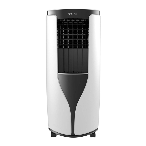
- Page 7 INSTALLATION INSTRUCTIONS Unit Overview Control Display Horizontal Louver Adjustment Vertical Louver Adjustment Caster Filter Cover Air-inlet Exhaust Hose Connection Remote Control Storage Pocket Drainage Port...
-
Page 8: Installation
INSTALLATION INSTRUCTIONS Parts and Tools Needed Parts Please Assemble Exhaust Hose Exhaust Nozzle Exhaust Nozzle Connection Bottom Exhaust Hose Drain Connector (1) Extension Panel Screw (14) Bracket Foam Seal Adjustment Panel Window Panel Foam with May Be Pre-Assembled Cord Hook (2) Pipe Clip Rubber Plug Adhesive (2) - Page 9 INSTALLATION INSTRUCTIONS Cord Hook Installation Cord Hook Screw Install the at the back of the Cord Hooks unit with 2 screws. The top Cord Hook should face upward, and the bottom should face downward. Cord Hook Wind the power cord around Cord Hooks NOTE: Do not...
- Page 10 INSTALLATION INSTRUCTIONS Drainage Hose Installation NOTE: Use the continuous drainage option from the drainage port. Install the drainage hose before using, otherwise poor drainage will affect the unit. Pipe Clip Drainage Port Screw Drainage Port Remove the at the Drainage Port, and fix the on the right rear side of the unit near Rubber Plug Pipe Clip...
- Page 11 INSTALLATION INSTRUCTIONS Vertical Double Hung Window Window Panel Spring Washers Nuts Exhaust Nozzle Support Inner Side Washers Bolts Screws Bolts Washers Protective Guard Rain Shield Nuts Spring Washers A) Insert into Exhaust Nozzle Window Panel A) Attach on the outer side of the Support B with Window Panel...
- Page 12 INSTALLATION INSTRUCTIONS Vertical Double Hung Window 20.5" 20.5" - 38.5" 38.5" - 56.7" cannot be Inner width of the window: Inner width of the window: Window Panel installed in windows less than 20.5" (52 cm)- 38.5" (98 cm) 38.5" (98 cm) - 56.7" (144 cm) 20.5"...
- Page 13 INSTALLATION INSTRUCTIONS Horizontal Sliding Window Window Panel Exhaust Nozzle Robert to insert Inner Side correct image Screws Protective Guard A) Attach on the outer side of the Support A A) Insert into Exhaust Nozzle Window Panel with Window Panel 2 Bolts, 2 Washers, 2 Spring in this order.
- Page 14 INSTALLATION INSTRUCTIONS Horizontal Sliding Window 20.5" 20.5" - 38.5" 38.5" - 56.7" cannot be Inner height of the window: Inner height of the window: Window Panel installed in windows less than 20.5" (52 cm)- 38.5" (98 cm) 38.5" (98 cm) - 56.7" (144 cm) 20.5"...
- Page 15 INSTALLATION AND DISASSEMBLY Exhaust Hose Connection Clockwise Clockwise Exhaust Nozzle Exhaust Hose Connection Exhaust Exhaust Hose Nozzle Bottom Rotate clockwise into Exhaust Hose Connection Exhaust Nozzle opposite ends of the Exhaust Hose Exhaust Hose Clasp Connection Groove Slide into the grooves located on the back of the unit. Exhaust Hose Connection...
- Page 16 INSTALLATION AND DISASSEMBLY Exhaust Hose Connection CORRECT CORRECT CORRECT INCORRECT Note: In order to improve cooling efficiency, the Exhaust Hose should be as short as possible, and without bends. Exhaust Hose Removal Exhaust Hose Upwards Connection Exhaust Clasp Nozzle Exhaust Exhaust Hose Hose...
-
Page 17: Operating Instructions
OPERATING INSTRUCTIONS Features of Your Portable A/C LCD Remote Control LCD remote control displays all settings. X-Fan Button On Remote Control By pressing this button in COOL or DRY mode the Icon “ ” will be displayed and the interior fan will continue to operate for a few minutes in order to disperse excess condensation. - Page 18 OPERATING INSTRUCTIONS Function & Control Display + / - Button Display Cool Mode Dry Mode Cool High Auto Mode Mode Sleep Speed Button Button Timer Button Button On/Off Button SYMBOL DESCRIPTION FUNCTION Power Button Turns air conditioner On and Off. When turned on, the display will show the set temperature, or time remaining Display on the Delay Timer.
- Page 19 OPERATING INSTRUCTIONS Remote Control Operation NOTICE: • The distance between remote and receiving window should be no more than 8 m (26 ft.), and there should be no obstacles between them. • When not using the remote control for extended periods of time, please take out the batteries.
- Page 20 OPERATING INSTRUCTIONS To Change Air Flow Direction CAUTION: Do not adjust the Horizontal Louver to the extreme left or right position in the COOL or DRY mode with the fan speed set to Low for an extended period of time. Condensation may form on the louvers. Horizontal Louver Adjustment Hold the Horizontal Louver as shown in the diagram and adjust...
-
Page 21: Cleaning And Maintenance
CLEANING AND MAINTENANCE WARNING • Turn off the air conditioner and disconnect the power cord from outlet before cleaning the air conditioner to avoid electric shock. • Do not wash the air conditioner with water to avoid electric shock. • Do not use harsh cleansers to clean the air conditioner. •... - Page 22 CLEANING AND MAINTENANCE Remove Collected Water: Continuous Drainage Lower Hole Option NOTE: During cooling or drying operations, water will condense and drain into the chassis. When the chassis is full with water, a buzzer will sound and “H8” will display on the unit. The unit will shut off.
- Page 23 CLEANING AND MAINTENANCE Remove Collected Water: Continuous Drainage Middle Hole Option ATTENTION: When using continuous drainage option from the middle hole, place portable on a level surface and make sure drainage hose is clear of any obstructions and is directed downward. Placing portable on an uneven surface or improper hose installation may result in water filling up the chassis and causing the unit to shut off.
- Page 24 CLEANING AND MAINTENANCE Remote Control Battery Replacement AAA Battery Signal Sender Reinstall Remove Battery Cover Replacement of Batteries in Remote Control 1. Press the back side of remote control marked with OPEN, as shown in the figure, and then push out the BATTERY COVER of battery box along the arrow direction.
-
Page 25: Before You Call
BEFORE YOU CALL WARNING If the below errors occur, please turn off the air conditioner and disconnect the power cord from the outlet immediately. Please contact Customer Service at once. • Power cord is overheating or damaged. • Abnormal sound during operation. •... - Page 26 Remote control is outside of range of the unit. Place remote within 8 m (26 ft.) of the unit. Remote control signal is obstructed- remove any item blocking front of unit. Low batteries. Replace batteries on remote control. IF THESE SOLUTIONS FAIL, PLEASE CALL 1-866-658-0466 FOR GREE CUSTOMER SERVICE...
- Page 27 1. Turn unit off, pull out power plug. Wait 10 minutes. Overcurrent protection 2. Plug unit in and turn on. 3. If code still appears, please contact Customer Service. IF THESE SOLUTIONS FAIL, PLEASE CALL 1-866-658-0466 FOR GREE CUSTOMER SERVICE...
-
Page 28: Warranty Statement
Air Conditioner unit. This warranty does not cover, and is not intended to exclude any liability on the part of GREE, whether under this warranty or implied by law for any indirect or consequential damages for breach of warranty. - Page 29 Gree Customer Service Hours: 9am–5pm CST Monday–Friday Phone: 1-866-658-0466 Email: customerservice@greeproducts.com Website: www.greeproducts.com M100517-5K6KPACS-US...
Need help?
Do you have a question about the GRP-E05SH-R4 and is the answer not in the manual?
Questions and answers