Table of Contents
Advertisement
Change for life
Owner's Manual
Original Instructions
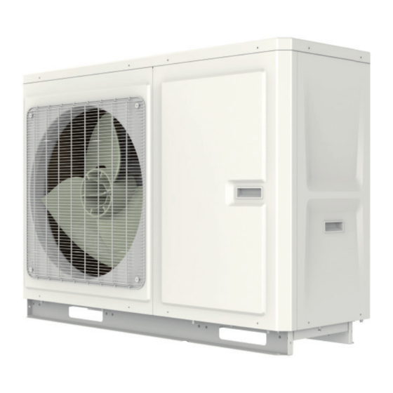
Air Conditioners
Air-to-water Heat Pump
GRS-CQ4.0Pd/NhG3-E
GRS-CQ6.0Pd/NhG3-E
GRS-CQ8.0Pd/NhG3-E
GRS-CQ10Pd/NhG3-E
GRS-CQ8.0Pd/NhG3-M
GRS-CQ10Pd/NhG3-M
GRS-CQ12Pd/NhG3-E
GRS-CQ14Pd/NhG3-E
GRS-CQ16Pd/NhG3-E
GRS-CQ12Pd/NhG3-M
GRS-CQ14Pd/NhG3-M
GRS-CQ16Pd/NhG3-M
GRS-CQ4.0Pd/NhG4-E
GRS-CQ6.0Pd/NhG4-E
GRS-CQ8.0Pd/NhG4-E
GRS-CQ10Pd/NhG4-E
GRS-CQ8.0Pd/NhG4-M
GRS-CQ10Pd/NhG4-M
GRS-CQ12Pd/NhG4-E
GRS-CQ14Pd/NhG4-E
GRS-CQ16Pd/NhG4-E
GRS-CQ12Pd/NhG4-M
GRS-CQ14Pd/NhG4-M
GRS-CQ16Pd/NhG4-M
MONOBLOC TYPE
Advertisement
Table of Contents


Need help?
Do you have a question about the GRS-CQ4.0Pd/NhG3-E and is the answer not in the manual?
Questions and answers