Table of Contents
Advertisement
Advertisement
Table of Contents

Related Manuals for Gree GRH120DB-K6NA1A


Summary of Contents for Gree GRH120DB-K6NA1A
- Page 1 Change for life Service Manual GREE ELECTRIC APPLIANCES, INC. OF ZHUHAI...
-
Page 2: Table Of Contents
6. Function and Control .............13 6.1 Remote Controller Introduction ................13 6.2 Control Panel Introduction .................15 6.3 GREE+ App Operation Manual ................16 6.4 Ewpe Smart App Operation Manual ..............17 6.5 Brief Description of Models and Functions ..........18 7. Notes for Installation and Maintenance .... - Page 3 8.6 Installing The Ceiling Assembly ...............27 8.7 Electrical Wiring ......................27 8.8 Completing The Installation ................28 9. Maintenance .................29 9.1 Error Code List ......................29 9.2 Procedure of Troubleshooting ................30 10. Exploded View and Parts List .......37 10.1 Indoor Unit ......................37 10.2 Outdoor Unit ......................38 11.
-
Page 4: Part Ⅰ : Technical Information
Outdoor Remote Model Product code Indoor model Outdoor model code product code Controller GRH120DB-K6NA1A CU050001400 GRH120DB-K6NA1A/I CU050N01400 GRH120DB-K6NA1A/O CU050W01400 GRH120DB-K6NA1A CU050001401 GRH120DB-K6NA1A/I CU050N01401 GRH120DB-K6NA1A/O CU050W01401 YAY1F2 GRH085DB-K6NA1A CU050001300 GRH085DB-K6NA1A/I CU050N01300 GRH085DB-K6NA1A/O CU050W01300 GRH085DB-K6NA1A CU050001301 GRH085DB-K6NA1A/I CU050N01301 GRH085DB-K6NA1A/O CU050W01301 Technical Information... -
Page 5: Specifications
2. Specifications Model GRH085DB-K6NA1A GRH085DB-K6NA1A Product Code CU050001300 CU050001301 Rated Voltage 220-240 220-240 Power Rated Frequency Supply Phases Cooling Capacity 2600 2600 Heating Capacity 2400 2400 Cooling Power Input 1160 1160 Heating Power Input 1000 1000 Cooling Current Input Heating Current Input Rated Input 1600 1600... - Page 6 Model GRH085DB-K6NA1A/O GRH085DB-K6NA1A/O Product Code CU050W01300 CU050W01301 Compressor Trademark HIGHLY HIGHLY SHANGHAI HIGHLY SHANGHAI HIGHLY Compressor Manufacturer ELECTRICAL APPLIANCES CO.,LTD ELECTRICAL APPLIANCES CO.,LTD Compressor Model GDD102SV-A3D GDD102SV-A3D Compressor Oil ACS-68R ACS-68R Compressor Type Rotary Rotary Compressor Locked Rotor Amp 18.9 18.9 Compressor Rated Load Amp 3.85...
- Page 7 Model GRH120DB-K6NA1A GRH120DB-K6NA1A Product Code CU050001400 CU050001401 Rated Voltage 220-240 220-240 Power Rated Frequency Supply Phases Cooling Capacity 3600 3600 Heating Capacity 3400 3400 Cooling Power Input 1270 1270 Heating Power Input 1170 1170 Cooling Current Input Heating Current Input...
- Page 8 Model GRH120DB-K6NA1A/O GRH120DB-K6NA1A/O Product Code CU050W01400 CU050W01401 Compressor Trademark HIGHLY HIGHLY SHANGHAI HIGHLY SHANGHAI HIGHLY Compressor Manufacturer ELECTRICAL APPLIANCES CO.,LTD ELECTRICAL APPLIANCES CO.,LTD Compressor Model GDD102SV-A3D GDD102SV-A3D Compressor Oil ACS-68R ACS-68R Compressor Type Rotary Rotary Compressor Locked Rotor Amp 18.9 18.9...
-
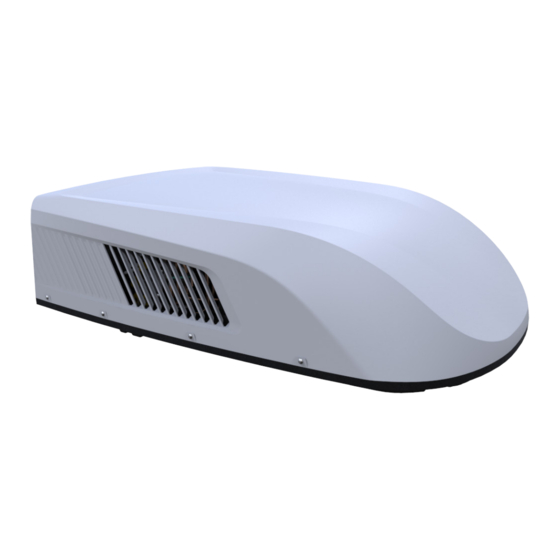
Page 9: Outline Dimension Diagram
3. Outline Dimension Diagram 3.1 Indoor Unit 3.2 Outdoor Unit 1077 Unit:mm Technical Information... -
Page 10: Refrigerant System Diagram
4. Refrigerant System Diagram CENTRIFUGAL FAN COOLED AIR CENTRIFUGAL FAN HOT DISCHARGED AIR HOT AIR COOLED AIR COMPRESSOR INDOOR COILS OUTDOOR COILS CAPILLARY STRAINER NOTES: COOLING MODE HEATING MODE REFRIGERANT FLOW DIRECTION COOLED AIR CENTRIFUGAL FAN AXIAL FAN HOT DISCHARGED AIR HOT AIR COOLED AIR COMPRESSOR... -
Page 11: Electrical Part
5. Electrical Part 5.1 Wiring Diagram ●Instruction Symbol Symbol Color Symbol Symbol Color Symbol Name White Green COMP Compressor Yellow Brown Grounding wire Blue YEGN Yellow/Green Black Violet Orange ● Indoor Unit CONNECTOR DISP1 DISPLAY BOARD ROOM ROOM SENSOR WIFI CONNECTOR WIFI LAMP... - Page 12 ● Outdoor Unit CAP. TUBE OUTDOOR OUTROOM 4-WAY TUBE SENSOR SENSOR SENSOR VALVE IN_FAN YEGN MOTOR (20K) (20K) (15K) (WH) (BK) 4WAY T-SEN DISP1 MAIN BOARD OFAN AC-L COMP YEGN CAP. POWER YEGN OUT_FAN COMP MOTOR CAP. COMP. 600007064532 These wiring diagrams are subject to change without notice; please refer to the one supplied with the unit. Technical Information...
-
Page 13: Pcb Printed Diagram
5.2 PCB Printed Diagram Silk screen on main board Name Name Control terminal of outdoor fan motor Live wire terminal Control terminal of indoor fan motor Fuse Neutral wire terminal Wiring terminal of compressore Neutral wire terminal Display terminal Control terminal of 4-way valve 10 Temperature sensor terminal Technical Information... - Page 14 Silk screen on display board Name Name Interface of WiFi Interface of lamp plate Interface of temperature sensor Interface of main board Technical Information...
-
Page 15: Function And Control
6. Function and Control 6.1 Remote Controller Introduction Introduction for buttons on remote controller Note: ● This is a general use remote controller. It could be used for the air conditioner with multifunction. For the functions which the model doesn't have, if press the corresponding button on the remote controller, the unit will keep the original running status. - Page 16 for a few minutes in order to dry the indoor unit even though Press "+" and "-" simultaneously to turn on or turn off child lock you have turned off the unit. After energization, X-FAN OFF is function. When child lock func-tion is on, " " icon is displayed defaulted.
-
Page 17: Control Panel Introduction
6.2 Control Panel Introduction Note: If the remote controller is missing, operate on the control panel. FILTER CHECK ON/OFF temp. COOL receiver indicator indicator indicator indicator window HEAT indicator Mode Button Fan Speed Button +/- Button Light Button ON/OFF Button Basic Functions of the Buttons 1.ON/OFF button Operation starts when pressing this button, and stops when pressing this button again. -
Page 18: Gree+ App Operation Manual
GREE+ App Download Linkage Scan the QR code or search "GREE+" in the application market to download and install it. When "GREE+" App is installed, register the account and add the device to achieve long-distance control and LAN control of Gree smart home appliances. -
Page 19: Ewpe Smart App Operation Manual
6.4 Ewpe Smart App Operation Manual Control Flow Chart Internet Cloud intelligent Home Wi-Fi Cellular/ home Other Wi-FI appliances Home wireless router Home Wi-Fi Operating Systems Requirement for User's smart phone: iOS system Android system Support iOS7.0 and Support Android 4.4 and above version above version Download and installation... -
Page 20: Brief Description Of Models And Functions
6.5 Brief Description of Models and Functions 1. Target Recreational Vehicles 2. Basic Functions 2.1 Cooling 2.1.1 Operating conditions and procedures a) Tinner amb ≥ Tpreset +1 F), cooling mode: compressor cycles on, fan motors will operate in set speed. b) Tinner amb ≤Tpreset -1 F), compressor and outdoor fan motors cycle off, indoor fan motor will operate in set speed. - Page 21 If the time is set within 10 hours, the timing interval is 0.5h; If the time is set more than 10 hours, the timing interval is 1h. 3.4 Memory Function The system will remember the settings when power is interrupted. The unit will automatically restart in the last setting used after the power is restored.
- Page 22 4.2 problem2: dual 8 nixie tube shows F1; What to do: make sure the indoor ambient temperature sensor is securely connected to the controller. 4.3 Problem3: dual-8 nixie tube shows F2; What to do: the indoor tube temperature sensor is not securely connected with the controller. Install it again or replace it with a new one. 4.4 problem4: dual 8 nixie tube shows F3;...
-
Page 23: Notes For Installation And Maintenance
7. Notes for Installation and Maintenance Safety Precautions: Important! 11. For the air conditioner without plug, an air switch must be installed in the circuit. The air switch should be all-pole Please read the safety precautions carefully before parting and the contact parting distance should be more than installation and maintenance. - Page 24 equipment manufacturer. Maintenance and repair requiring the Safety Precautions for Refrigerant assistance of other skilled personnel shall be carried out under the supervision of the person competent in the use of flammable ●To realize the function of the unit, a special refrigerant refrigerants.
- Page 25 that the work is carried out. The ventilation should safely disperse ●Repair to intrinsically safe components any released refrigerant and preferably expel it externally into the Do not apply any permanent inductive or capacitance loads to the atmosphere. circuit without ensuring that this will not exceed the permissible voltage and current permitted for the equipment in use.
- Page 26 shall not be used for purging refrigerant systems. equipment are closed off. For appliances containing flammable refrigerants, flushing shall k. Recovered refrigerant shall not be charged into another be achieved by breaking the vacuum in the system with OFN refrigeration system unless it has been cleaned and checked. and continuing to fill until the working pressure is achieved, then venting to atmosphere, and finally pulling down to a vacuum.
-
Page 27: Installation
8. Installation 8.2 Before installation 8.1 Accessory list Test run the unit with proper power supply. Refer to the operation instruction section in the Owner’s Manual Operation & Installation. Make sure all the controls operate correctly then disconnect the power supply of the unit. WARNING 1. - Page 28 Below Level 0° Max Select the installation position for the recreational vehicle air conditioner This mounting plat of switchover opening is applicable for Gree Level recreational vehicle air conditioner. The opening size of installation port on the top of the vehicle must Above or Below Level 5°...
-
Page 29: Mounting Outdoor Unit
8.5 Mounting Outdoor Unit assembly. Stick the sponge and foam assembly with double faced adhesive tape (prepared by user) (See Fig.10, Fig.11). 1.Open the package and take out the outdoor unit. 6.Install the foam assembly on the air duct assembly. Use 4 screw 1) When taking out the outdoor unit after unpacking, do not lift the bolts to fix the air duct assembly onto the mounting plat. -
Page 30: Completing The Installation
indoor electrical wire display board Fig.13 Fig.14 4. Use protective sleeve to wrap the wiring terminal, stick the protective sleeve and then use cable tie to bundle them tightly. Note: 1. The fixing position of cable must be at both ends of wiring terminal. -
Page 31: Maintenance
9. Maintenance 9.1 Error Code List Display Method Malfunction of Indoor Unit A/C Status Possible Causes Name (Error Code) 1. The wiring terminal between indoor ambient temperature sensor and Indoor ambient controller is loosened or poorly contacted; temperature 2. There’s short circuit due to trip-over of the parts on controller; sensor 3.Indoor ambient temperature sensor is damaged (Please check it by is open/... -
Page 32: Procedure Of Troubleshooting
9.2 Procedure of Troubleshooting 1. Malfunction of Temperature Sensor F1 Start Is the wiring terminal between the temperature sensor and the controller loosened or poorly contacted? Insert the temperature sensor tightly Is malfunction eliminated Is there short circuit due to trip- over of the parts Make the parts upright Is malfunction... - Page 33 2. Malfunction of detecting plate(WIFI) JF Start check if the connection wire are correctly connected detecting Replace the plate with the same model Is malfunction eliminated Replace the mainboard with the same model The end Installation and Maintenance...
- Page 34 3. Overload malfunction E8 Troubleshooting for E8 malfunction Operate the unit after ambient tempeature and Whether the environment Malfunction is humidity is decreased or move the unit to the eliminated. is formidable place with low abient temprature and humidity. Heat exchangers are Clean the heat exchangers and remove Malfunction is too dirty or the air inlet/outlet...
- Page 35 4. Malfunction of Insufficient fluorine protection F0 Troubleshooting for F0 malfunction Heat exchangers are Clean the heat exchangers and remove Malfunction is too dirty or the air inlet/outlet eliminated. blockage of air inlet/outlet. is blocked. Compressor doesn't work Malfunction is Make compressor run normally.
- Page 36 5. Overload malfunction H3 Troubleshooting for H3 malfunction Heat exchangers are Clean the heat exchangers and remove Malfunction is too dirty or the air inlet/outlet eliminated. blockage of air inlet/outlet. is blocked. Fan motor doesn't work at Check motor and reinstall the moto to Malfunction is a normal fan speed;...
- Page 37 6. Overload malfunction PL Start Start Check whether the power supply voltage is lower than 184V? Cut off the power and confirm the supply power is not lower than 184V. After that, put through the power again. Is the malfunction Replace the main board eliminated? Installation and Maintenance...
- Page 38 7. Communication malfunction E6 Start Did the equipment operate normally before the failure occurs? Check the wiring of the indoor and outdoor units with reference to the wiring diagram Check wiring inside of the indoor and Is the connection right? outdoor units Correctly connect the corresponding wires for...
-
Page 39: Exploded View And Parts List
10. Exploded View and Parts List 10.1 Indoor Unit The component picture is only for reference; please refer to the actual product. Description Description Foam Front Panel Air Duct Sub-assy Magnet Sub-assy Air Outlet Mid-panel Latch Base Plate Front Grill Air Outlet Frame Sub-assy Healthy Filter Shaft of Guide Louver... -
Page 40: Outdoor Unit
10.2 Outdoor Unit The component is only for rererence;please refer to the actual product Installation and Maintenance... - Page 41 Description Description Condenser Assy Foam Capillary Sub-assy Sponge (sealing strip) Compressor and Fittings Chassis Assy Compressor Gasket Sponge 4-Way Valve Assy Motor base Assy Water baffle (4-way valve) Electric Box Assy Water baffle (fixing pipe) Main Board Centrifugal fan (inside) Capacitor CBB61S Centrifugal fan blade Capacitor CBB65...
-
Page 42: Removal Procedure
11. Removal Procedure 11.1 Removal Procedure of Indoor Unit Step Procedure 1.Remove air-in grille and the filter Press both ends of air-outlet grille to unlock the door switch and then remove the air-in grille and the filter. 2. Remove front panel sub-assy Loose 4 screws at both ends and then remove the panel sub-assy downwards. - Page 43 Step Procedure Screw 4. Remove base plate and the middle air-outlet panel Loose 2 screws at both ends; loose 7 clasps at both sides and then separate the base plate and the middle air-outlet panel. 5. Remove detecting board Loose 1 screw on the top; remove the detecting board. Screw Detecting board 6.
- Page 44 Step Procedure 7.Remove display module Screw Loose 1 screw as shown in the figure, and rotate the display module in clockwise direction to remove it. 8. Remove air-outlet frame sub-assy clasp Press inwards to press out the 5 clasps on the outside of the air-outlet frame sub-assy, so that the clasps out of the panel and pull down, so that the inside 4 limit clasps out can remove the air-outlet frame sub-assy.
-
Page 45: Removal Procedure Of Outdoor Unit
11.2 Removal Procedure of Outdoor Unit Caution: discharge the refrigerant completely before removal. Step Procedure 1. Outdoor unit diagram 2.Remove outer case Remove screws fixing outer case. Lift up to remove the outer case. screws screws Installation and Maintenance... - Page 46 Step Procedure 3.Remove foam(inner side) Remove screws fixing the foam(inner side) and then remove the foam(inner side). screws 4.Remove foam(outside) Remove screws fixing the foam(outside) and then remove the foam(outside). foam sub-assy screw 5.Remove Electric Box Cover Electric box cover Remove screws fixing the electric box cover and then remove the electric box cover.
- Page 47 Step Procedure Main Board 7.Remove electric box assy Lift the mainboard, disconnect each wiring terminal on the mainboard; Remove screws fixing the electric box assy, remove the ground screw on the condenser and then lift the electric box assy to remove it. Screws Screws 8.Remove water baffle...
- Page 48 Step Procedure Remove screw fixing the water baffle (fixing pipe); remove screws fixing the tube clip, then remove the water baffle(fixing pipe). Tube Clip Screws Screw 9.Remove Magnet Coil Remove bolt fixing the magnet coil and then remove the magnet coil. Magnet Coil Bolt 10.Remove Capillary Sub-assy...
- Page 49 Step Procedure 10.Remove 4-way valve assy Welding joint Unsolder the welding joint connecting the 4-way valve assy and then unsolder the 4-way valve assy. Note: 1.Before unsoldering the welding joint, please make sure the refrigerant is discharged completely. 2.Before unsoldering the welding joint connecting the 4-way valve, wrap the 4-way valve assy with a wet cloth completely to avoid damage to the valve caused by high temperature.
- Page 50 Step Procedure 13.Remove Centrifugal Fan Blade Centrifugal fan blade(inside) Screw Remove screws fixing the centrifugal fan; Pull out in the direction of the arrow, remove the centrifugal fan. Centrifugal fan blade(outside) Screws 14.Remove Compressor Nuts with Washer Remove nuts with washer fixing the compressor; remove the compressor.
-
Page 51: Appendix
Appendix Appendix 1: Reference Sheet of Celsius and Fahrenheit Conversion formula for Fahrenheit degree and Celsius degree: Tf=Tcx1.8+32 Set temperature Fahrenheit display Fahrenheit Celsius Fahrenheit display Fahrenheit Celsius Fahrenheit display Fahrenheit Celsius temperature(℉) temperature(℉) temperature(℉) (℉) (℃) (℉) (℃) (℉) (℃)... -
Page 52: Appendix 2: List Of Resistance For Temperature Sensor
Appendix 2: List of Resistance for Temperature Sensor Resistance Table of Ambient Temperature Sensor for Indoor and Outdoor Units(15K) Temp( Resistance(kΩ) Temp( Resistance(kΩ) Temp( Resistance(kΩ) Temp( Resistance(kΩ) 138.10 49.02 18.75 7.97 128.60 44.31 17.14 7.35 115.00 40.09 15.68 6.79 102.90 36.32 14.36 6.28... - Page 53 JF00304635 GREE ELECTRIC APPLIANCES, INC. OF ZHUHAI Add: West Jinji Rd, Qianshan, Zhuhai,Guangdong, China, 519070 Tel: (+86-756) 8522219 Fax: (+86-756) 8669426 E-mail: global@cn.gree.com For product improvement, specifications and appearance in this manual are subject to change without prior notice.
Need help?
Do you have a question about the GRH120DB-K6NA1A and is the answer not in the manual?
Questions and answers