General safety summary ..................Service safety summary ..................Terms in this manual ..................Symbols and terms on the product ................Compliance information ................... EMC compliance (TCPA300/400 only) ..............Safety compliance ..................... Environmental considerations ................Operating considerations ..................Installation......................Standard accessories..................
Page 4
Table of Contents Amplifiers and Current Probes Compliance and Safety Instructions...
Carefully read all instructions. Retain these instructions for future reference. TCPA300/400 only: This product shall be used in accordance with local and national codes. For correct and safe operation of the product, it is essential that you follow generally accepted safety procedures in addition to the safety precautions specified...
Page 6
Use only current probes, test leads, and adapters supplied with the product, or indicated by Tektronix to be suitable for the product. Observe all terminal ratings. TCPA300/400 only: To avoid fire or shock hazard, observe all ratings and markings on the product. Consult the product manual for further ratings information before making connections to the product.
Page 7
Do not push objects into any of the openings. Probes and test leads Before connecting probes or test leads to the TCPA300/400, connect the power cord from the power connector to a properly grounded power outlet. Keep fingers behind the protective barrier, protective finger guard, or tactile indicator on the probes.
Important safety information Service safety summary The Service safety summary section contains additional information required to safely perform service on the product. Only qualified personnel should perform service procedures. Read this Service safety summary and the General safety summary before performing any service procedures. To avoid electric shock.
(This symbol may also be used to refer the user to ratings in the manual.) Amplifiers The following symbol(s) may appear on the TCPA300/400 amplifiers: Probes The following symbol(s) may appear on the TCP303/305A/312A/404XL current probes: Amplifiers and Current Probes Compliance and Safety Instructions...
Tektronix, Inc. PO Box 500, MS 19-045 Beaverton, OR 97077, USA www.tek.com EMC compliance (TCPA300/400 only) EU EMC Directive Meets intent of Directive 2014/30/EU for Electromagnetic Compatibility. Compliance was demonstrated to the following specifications as listed in the Official Journal of the European Communities: EN 61326-1, EN 61326-2-1.
EN 61010-2-032. (TCP303/305A/312A/404XL only) Particular requirements for handheld current clamps for electrical measurement and test equipment. U.S. nationally recognized UL 61010-1. (TCPA300/400 and TCP305A/312A only) Safety Requirements for Electrical Equipment for Measurement, Control, and Laboratory Use – testing laboratory listing Part 1: General Requirements.
Page 12
Equipment type Test and measuring equipment. Safety class TCPA300/400 only: Class 1 – grounded product. Pollution degree A measure of the contaminants that could occur in the environment around and within a product. Typically the internal environment inside a product is descriptions considered to be the same as the external.
Only measurement circuits have a measurement category rating. Other circuits within the product do not have either rating. Mains overvoltage TCPA300/400 only: Overvoltage category II (as defined in IEC 61010-1). category rating Environmental considerations This section provides information about the environmental impact of the product.
Nonoperating Up to 12,192 m (40,000 ft.) Pollution degree 2, Indoor use only TCPA300 and TCPA400 Characteristic TCPA300 and TCPA400 amplifiers power Input voltage 100–240 VAC, 47 Hz to 440 Hz, single phase Maximum power 50 watts maximum TCP312A and TCP305A...
Page 15
WARNING: To reduce the risk of fire or burn, refer to TCP404XL Maximum Measurement Times for intermittent operation in the TCPA300/400 Amplifiers and TCP300A/400 Series Current Probes User Manual, Tektronix part number 077-1183-xx, for maximum currents and duty cycles before use.
Installation Installation The TCPA300 and TCPA400 current probe amplifiers let you use one probe to simultaneously measure AC and DC current. The amplifiers convert the sensed current into a proportional voltage signal that you can measure directly with an oscilloscope. The amplifiers and associated probes provide these features:...
One-turn 50 Ω HF current loop. Two versions are available; one for each style of probe. The current loops are used in the performance verification procedures for checking the performance of the TCPA300 Amplifier and the compatible probes. 50 Ω feedthrough termination, 2 W (Tektronix part number 011-0049-xx) 50 Ω...
TCPA300 and TCPA400 Current Probe Amplifiers. Connect the amplifier to an oscilloscope You will need an oscilloscope to display the TCPA300 and TCPA400 measurement output. To use the full dynamic range of the probe/amplifier combination, the oscilloscope must be capable of displaying a vertical scale factor of 1 mV/div to 1 V/div.
Installation To utilize the full bandwidth capability of the TCPA300 and TCPA400 and attached current probe, the oscilloscope bandwidth must be approximately five times that of the current probe. For example, when using a TCP312A Current Probe, the oscilloscope bandwidth must be at least 500 MHz. When using a TCP305A Current Probe, the oscilloscope bandwidth must be at least 250 MHz.
If a probe requires adjustment, information is available in the service manual. The adjustment procedure must be performed only by qualified service personnel. Contact your nearest Tektronix Service Center if you need more assistance. Amplifiers and Current Probes Compliance and Safety Instructions...
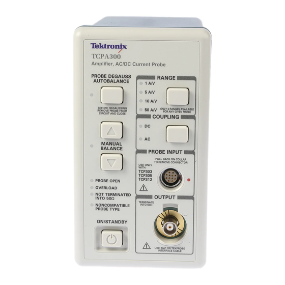
NONCOMPATIBLE PROBE TYPE. 4. The ON/STANDBY button turns on power to the amplifier. 5. The TCPA300 and TCPA400 output appears at the OUTPUT connector. Connect this to a 50 Ω input of your oscilloscope. Amplifiers and Current Probes Compliance and Safety Instructions...
Operate the amplifier 6. The current probes connect to the TCPA300 and TCPA400 at the PROBE INPUT connector. 7. The COUPLING button selects AC or DC probe coupling, as indicated by the LEDs. 8. The RANGE button toggles between the two scale factors that are available for the attached probe (TCPA300 only).
5 °C. WARNING. To avoid personal injury or equipment damage, do not exceed the specified electrical limits of the TCPA300 and TCPA400 Amplifiers or any applicable probe accessories. Amplifiers and Current Probes Compliance and Safety Instructions...
Operate the current probe Operate the current probe Basic operation 1. Connect the probe to the amplifier. (See page 16, Connect the probe to the amplifier.) 2. TCP305A and TCP312A only: If desired, install the ground lead to the probe. (See page 25, Use the ground lead.) 3.
To improve EMI rejection at high frequencies, use the optional ground lead. Refer to the TCPA300/400 Amplifiers and TCP300A/400 Series Current Probes User Manual, Tektronix part number 077-1183-xx, for additional instructions.
Page 26
Operate the current probe To operate the probe: 1. To close (lock) the probe, push the slide forward until the detent snaps into place. NOTE. The slider must be in the closed (locked) position to degauss the probe. 2. To open (unlock) the probe, pull the slide back until the jaw is open. 3.
Page 27
Operate the current probe TCP303 and TCP404XL The slide operation of the TCP303 and TCP404XL current probes is shown in the following illustration. slide operation To operate the probe: 1. Press the bottom of the lock button to unlock the probe. 2.
Operate the current probe Degauss and autobalance the current probe Degauss the probe to remove any residual magnetization from the probe core. Such residual magnetization can induce measurement error. Autobalancing removes unwanted DC offsets in the amplifier circuitry. Failure to degauss the probe is a leading cause of measurement errors.
Operate the current probe Use the ground lead The TCP305A and TCP312A probes include a 6-inch ground lead. The ground lead grounds the shield around the probe transformer at the probe end of the cable. This allows you to move the ground connection closer to the circuit you are measuring, thereby improving high frequency shielding.
Operate the current probe Make DC current measurements To measure DC current, first degauss the probe. (See page 24, Degauss and autobalance the current probe.) 1. Verify that the amplifier and the oscilloscope input coupling are set to DC, and the input impedance is set to 50 Ω. 2.
Page 31
Operate the current probe The current probe is shown connected to a power supply line. (See Figure 5.) Notice that the probe arrow points toward the negative terminal of the power supply to conform to the conventional current flow of positive (+) to negative (-). To measure DC current, perform these steps: 1.
Operate the current probe Make AC current measurements To measure AC current only, and remove the DC component of the current being measured, follow the instructions below. These are identical to the instructions for DC current measurements except that the amplifier coupling in step 2 is set to AC. 1.
Need help?
Do you have a question about the TCPA300 and is the answer not in the manual?
Questions and answers