Table of Contents
Advertisement
Quick Links
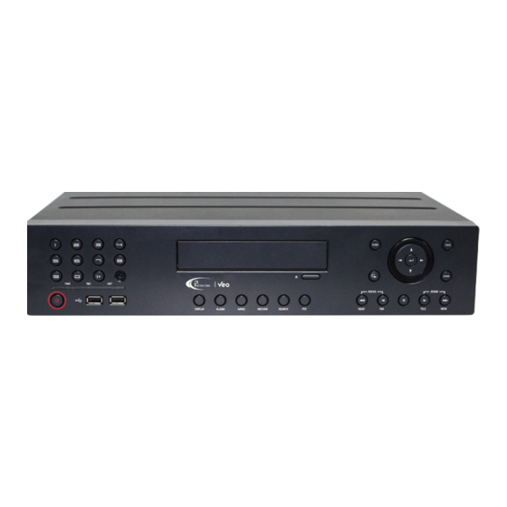
Veo16p Embedded HVR
Thank you for purchasing i3's Embedded HVR Veo16p. Your HVR supports a total of 16
video inputs: IP (select i3 Annexxus models only) or analog/HD-TVI analog.
The following items should be included with your HVR. If any of these items are
missing, please contact your dealer or call our Customer Care Department toll free at
1.866.840.0004.
ACCESSORIES
1. Power Cable (x1).
2. 12V DC Power Adapter (x1)
3. Power cable retainer clip (x1)
4. Hard Drive screws (x12)
INSTALLATION REQUIREMENTS
When installing your Veo16p be sure to avoid:
• Temperatures outside of the acceptable 20°C-25°C (68°F -77°F)
• Humidity outside of acceptable range of 20%-80%, non-condensing
• Contaminants such as dust and smoke
• Areas with strong magnetic fields or mechanical vibrations
Important: an Uninterrupted Power Supply (UPS), minimum 1000 VA, with
a constant power of 118 to 120 AC must be used with each i3 HVR Server
to ensure longevity and to maintain warranty.
HVR COMPONENTS
1
2
3 4 5
13
14
15
16
17
1
RCA Audio input ports (x16)
BNC Camera ports. Connect up to 16
2
analog cameras (max. 16 IP+analog).
3
RCA Audio Output (speaker) port
4
BNC Spot Out monitor ports (x2)
5
VGA monitor port
6
HDMI monitor port
7
eSATA port for external storage
USB port. Connect USB mouse or USB
8
storage.
WAN / LAN Ethernet ports.Connect a
switch or a hub to WAN port. Connect
9
the switch with up to 16 i3 IP cameras
(Ax45/Ax47/Ax67) to LAN port.
(max. 16 IP+analog)
Alarm In (x18), Alarm Out (x8), Relay
10
(x8), RS485 (x2) ports
11
12V DC Power Adapter port (provided)
Secure the power cable with the power
cable retainer clip, then fasten retainer
12
clip to the opening to help prevent
unintended disconnection of the power.
13
Power button. Press to turn the HVR on.
Channel selection buttons. Enter the
14
channel number to display individual
channels in the full screen mode.
i3 INTERNATIONAL INC.
1.866.840.0004
www.i3international.com
i3-TRNG-DVR-Veo16p.indd
5. USB Mouse (x1)
6. Remote Control and 2x AAA batteries
7. 7P Terminal block (x2). (Pre-installed).
8. 10P Terminal block (x4). (Pre-installed)
9
6 7 8
10 11
12
26
27
28
18 19 20
21 22
23
24
25
USB ports x2. Connect USB mouse or
15
USB storage.
DISPLAY. Changes the camera split
16
screen: 1, 2x2, 3x3 or 4x4
ALARM. Displays alarm status in a
17
popup window.
18
MENU. Displays system menu.
19
ARCHIVE. Displays backup mode.
20
SEARCH. Displays Time Search mode.
21
PTZ. Displays PTZ Control mode.
22
CD/DVD eject button
FOCUS. Focus selected PTZ camera
23
Near/Far.
24
Pause. Freezes the playback video.
ZOOM IN/OUT. Zoom selected PTZ
25
camera In (tele) or Out (wide).
26
PANIC. Start the emergency recording.
Menu navigation buttons. Use the
arrows to move through the system
27
menus. Use the Enter button in the
middle to select a menu item or
confirm a setting.
28
RETURN. Return to the previous menu.
LOCK. Lock Veo16p to prevent all
29
operations.
ZOOM. Enter the digital zoom mode.
30
Then use Zoom In/Out buttons (#25)
U.S.A
4450 Witmer Industrial Estates Unit 4
Niagara Falls, NY 14305
Quick Installation Guide
INSTALLATION
Before installation: Ground yourself. This will remove any static electrical charge your
body might be carrying.
STEP 1
Plug the mouse into the USB port in the front
STEP 2
Plug the main monitor into the VGA
To connect a DVI monitor, use HDMI-DVI adapter (not included).
Note: For proper display, your main monitor must support 1920 x1080 at 60Hz.
STEP 3
Connect Veo16p HVR to the network.
port. Connect the switch with i3 IP cameras (Ax47/67, Ax45/65), if using, to the LAN port.
Note: Configure the IP cameras' IP address before connecting to Veo16p.
STEP 4
Connect up to 16 analog cameras
PTZ cameras, connect RS485 communication cable to the corresponding ports on the
back of the HVR. Connect up to 16 i3 IP cameras to the LAN NIC port. See CONNECTING
REMOTELY via INTERNET EXPLORER for more information.
The total number of cameras supported: 16, select i3 IP cameras, analog/HD-TVI analog
or a combination of the two.
STEP 5
Connect other peripheral devices, if using, such as RCA Audio Inputs/Output
4
Spot Out monitor(s)
, eSATA storage
STEP 6
Connect the provided 12V DC Power Adapter to the
11
power port
on the back of the HVR. Secure the power
cable with the power cable retainer clip (provided) then
fasten retainer clip to the opening
29
unintended disconnection of the power.
30
STEP 7
Connect the power cable to the Uninterruptible Power Supply (UPS), 1000VA min., to
maintain warranty. Connect the UPS to the Power Source / power outlet.
STEP 8
The system will power on automatically. If this does not happen, press the power button
on the front of Veo16p HVR.
BASIC LAYOUT
HD Analog
Cameras x16
Mic
Speaker
VGA
Monitor
SPOT
Monitor
HDMI
Monitor
Canada 780 Birchmount Road, Unit 16,
QR Code for Complete
User Manual
15
8
or the back
of the unit.
5
6
or the HDMI port
on the motherboard.
9
Connect a switch or a hub to the HVR's WAN
2
to the BNC ports on the back of the unit. If using
7
10
, Alarm IN/OUT devices
12
to help prevent
13
The system will then power up.
IP Router or
USB
Gigabit Switch
Mouse
e-SATA
Alarm IN /
Storage
Sensor x18
Switch with 16 i3 IP cameras
Scarborough, ON, M1K 5H4
1 3
,
, etc.
RS232
Alarm
RS485
OUT x8
Control
Devices
Advertisement
Table of Contents

Related Manuals for i3 International Veo16p


Summary of Contents for i3 International Veo16p
- Page 1 User Manual INSTALLATION Thank you for purchasing i3’s Embedded HVR Veo16p. Your HVR supports a total of 16 video inputs: IP (select i3 Annexxus models only) or analog/HD-TVI analog. Before installation: Ground yourself. This will remove any static electrical charge your The following items should be included with your HVR.
- Page 2 SET YOUR TIME ZONE When the system starts, the login screen appears. Use the USB mouse and the on-screen All i3 international HVRs are virtual keyboard to enter USER ID and set to EST - Eastern Time Zone PASSWORD and click OK.
- Page 3 (Must be first configured in OPERATION MODE > PRE-RECORDING TIME.) Green: Continuous Recording Red: Alarm Recording Blue: Motion Recording Yellow: Panic Recording i3 INTERNATIONAL INC. 1.866.840.0004 U.S.A 4450 Witmer Industrial Estates Unit 4 Canada 780 Birchmount Road, Unit 16, www.i3international.com Niagara Falls, NY 14305 Scarborough, ON, M1K 5H4 i3-TRNG-DVR-Veo16p-QSG.indd...
- Page 4 CONNECTING REMOTELY via INTERNET EXPLORER Start by configuring your HVR for remote access. 1. Connect a Gigabit switch to your Veo16p WAN port to connect the system to the Internet. 2. Connect a switch with up to 16 supported i3 IP cameras (Ax45/47/67) to your Veo16p LAN port 3.
Need help?
Do you have a question about the Veo16p and is the answer not in the manual?
Questions and answers