
Subscribe to Our Youtube Channel
Related Manuals for Manitowoc CNF0201


Summary of Contents for Manitowoc CNF0201
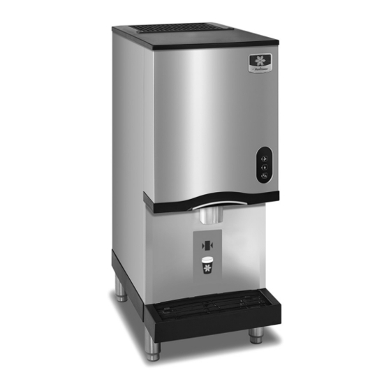
- Page 1 Engineered for Ease Countertop Nugget Ice Machines CNF0201 & CNF0202 Technician’s Handbook Part Number 000015432 Rev02 5/21...
- Page 3 Safety Notices Read these precautions to prevent personal injury: • Read this manual thoroughly before operating, installing or performing maintenance on the equipment. Failure to follow instructions in this manual can cause property damage, injury or death. • Routine adjustments and maintenance procedures outlined in this manual are not covered by the warranty.
- Page 4 Warning Follow these electrical requirements during installation of this equipment. • All field wiring must conform to all applicable codes of the authority having jurisdiction. It is the responsibility of the end user to provide the disconnect means to satisfy local codes. Refer to rating plate for proper voltage.
- Page 5 Warning Follow these precautions to prevent personal injury during installation of this equipment: • Installation must comply with all applicable equipment fire and health codes with the authority having jurisdiction. • To avoid instability the installation area must be capable of supporting the combined weight of the equipment and product.
- Page 6 Warning Follow these precautions to prevent personal injury while operating or maintaining this equipment. • Legs must be installed and the legs must be screwed in completely. • Some 50 Hz models may contain up to 150 grams of R290 (propane) refrigerant. R290 (propane) is flammable in concentrations of air between approximately 2.1% and 9.5% by volume (LEL lower explosion limit and UEL upper explosion limit).
- Page 7 Warning Follow these precautions to prevent personal injury while operating or maintaining this equipment. • Objects placed or dropped in the bin can affect human health and safety. Locate and remove any objects immediately. • Never use sharp objects or tools to remove ice or frost.
- Page 8 Warning Follow these precautions to prevent personal injury during use and maintenance of this equipment: • It is the responsibility of the equipment owner to perform a Personal Protective Equipment Hazard Assessment to ensure adequate protection during maintenance procedures. • Do Not Store Or Use Gasoline Or Other Flammable Vapors Or Liquids In The Vicinity Of This Or Any Other Appliance.
-
Page 9: Table Of Contents
Model/Serial Number Location . . . . . . . . . . . . . . . 13 Manitowoc Cleaner and Sanitizer . . . . . . . . . . . . . 13 Legs . - Page 10 Maintenance Manitowoc’s Cleaning Technology . . . . . . . . . . . . 26 Exterior Cleaning . . . . . . . . . . . . . . . . . . . . . . . . . . 28 Remedial Cleaning Procedure .
- Page 11 Component Check Procedures Electrical Components . . . . . . . . . . . . . . . . . . . . . . . . 75 Main Fuse .
- Page 12 CNF0201 - CNF0202 . . . . . . . . . . . . . . . . . . .
-
Page 13: General Information
Model/Serial Number Location These numbers are required when requesting information from your local Manitowoc Distributor, service representative, or Manitowoc Ice, Inc. The model and serial number are listed on the OWNER WARRANTY REGISTRATION CARD. They are also listed on the MODEL/ SERIAL NUMBER DECAL affixed to the ice machine. -
Page 14: Legs
Legs Optional four inch adjustable legs are available. SEALING TO COUNTERTOP OR STAND Ice machines installed without legs must be sealed to the countertop or stand. This prevent liquids or debris from infiltrating beneath the ice machine. Touchless Sensing Option Touchless sensing can be ordered installed on the ice machine from the factory or a field conversion kit is available. -
Page 15: Installation
Installation Warning PERSONAL INJURY POTENTIAL Remove all ice machine panels before lifting and installing. Location of Ice Machine The location selected for the ice machine must meet the following criteria. If any of these criteria are not met, select another location. •... -
Page 16: Ice Machine Clearance Requirements
Ice Machine Clearance Requirements CNF0201 - CNF0202 Self-Contained Air-Cooled 24" (61.0 cm) Sides 8" (20.3 cm) Back 5" (12.7 cm) Ice Machine Heat of Rejection Series Ice Machine Heat of Rejection* Air Conditioning CNF0201 - CNF0202 2,300 * BTU/Hour. Because the heat of rejection varies during the ice making cycle, the figure shown is an average. -
Page 17: Electrical Service
Self Contained Air-Cooled Voltage Phase Max. Fuse/ Ice Machine Total Amps Cycle Circuit Breaker CNF0201 115/1/60 10.3* CNF0202 230/1/50 5.4* *Indicates preliminary data - Model/Serial plate information overrides the data in this chart. Part Number 000015432 Rev02 5/21... -
Page 18: Ice Machine Head Section Water
Important If you are installing a Manitowoc water filter system, refer to the Installation Instructions supplied with the filter system for ice making water inlet connections. -
Page 19: Drain Connections
DRAIN CONNECTIONS Follow these guidelines when installing drain lines to prevent drain water from flowing back into the ice machine and storage bin: • Drain lines must have a 1.5 in. drop per 5 ft. of run (2.5 cm per meter), and must not create traps. •... - Page 20 THIS PAGE INTENTIONALLY LEFT BLANK Part Number 000015432 Rev02 5/21...
-
Page 21: Operation
Operation Ice Making Sequence of Operation CNF0201 - CNF0202 NUGGET MACHINES Ice Making Sequence of Operation PRIOR TO START-UP When the toggle switch is placed in the ICE position, the following must occur in the listed order before ice making will start. - Page 22 AUTOMATIC SHUTOFF When the ice damper is held open by ice, the gear motor, compressor and condenser fan de-energize. The ice machine will remain off until the 15-minute delay period expires and the ice damper closes. RESTART AFTER AUTOMATIC SHUTOFF The 15-minute delay period must be expired.
-
Page 23: Touch Pad Sequence Of Operation
Control Board Features POWER INTERRUPTION DELAY If power is disconnected, the ice machine stops. When power is reapplied, a 15-minute delay is initiated. SAFEGUARDS The ice machine control board has safety features to protect the ice machine from severe failures. The ice machine will stop when conditions arise that would cause major component failure. -
Page 24: Sequence Of Operation Chart
Part Number 000015432 Rev02 5/21... -
Page 25: Maintenance
Maintenance procedures or failures due to a lack of maintenance are not covered by the warranty. Manitowoc Ice Machine Cleaner/Descaler and Sanitizer are the only products approved for use in Manitowoc ice machines. Caution Use the correct Manitowoc approved metal safe Ice Machine Cleaner/Descaler (part number 000000084) and Sanitizer (part number 9405653). -
Page 26: Manitowoc's Cleaning Technology
Manitowoc’s Cleaning Technology Manitowoc CNF0201 - CNF0202 Ice Machines allow the initiation and completion of a cleaning cycle at the flip of a switch. This cycle will permit descaling or sanitizing all surfaces that come in contact with the water distribution system. - Page 27 Detailed Descaling/Sanitizing Procedure This procedure must be performed a minimum of once every six months: • All ice must be removed from the bin/dispenser. • The ice machine and bin/dispenser must be disassembled, descaled and sanitized. • The ice machine produces ice with the descaler and sanitizer solutions.
-
Page 28: Exterior Cleaning
EXTERIOR CLEANING Clean the area around the ice machine as often as necessary to maintain cleanliness and efficient operation. Use cleaners designed for use with stainless steel products. Sponge any dust and dirt off the outside of the ice machine with mild soap and water. -
Page 29: Remedial Cleaning Procedure
It is not used to remove algae or slime. Refer to “Sanitizing Procedure” for removal of algae and slime. To initiate a descaling cycle using Manitowoc’s Cleaning Technology use the following procedure. To start a cycle, move the toggle switch to the Step 1 CLEAN position. - Page 30 Add solution here WATER ICE / WATER The ice machine will run a wash cycle, a series Step 3 of rinse cycles and then stop. This entire cycle lasts approximately 30 minutes. NOTE: Periodic cleaning must be performed on adjacent surface areas not contacted by the water distribution system.
- Page 31 3. To abort the clean cycle move the toggle switch from CLEAN to OFF to CLEAN and back to OFF within a 15 second time period. Manitowoc recommends disassembling, descaling and sanitizing the ice machine and dispenser every six months. Part Number 000015432 Rev02 5/21...
-
Page 32: Heavily Scaled Procedure
OFF position. Refer to chart and add the correct amount of Step 6 cleaner for your model ice machine. Model Amount of Cleaner/Descaler Part Number 000000084 CNF0201 CNF0202 12 ounces (355 ml) Part Number 000015432 Rev02 5/21... - Page 33 Add solution here WATER ICE / WATER Turn on the water supply to the ice machine. Step 7 Important Leave the descaler/water solution in the evaporator for a minimum of 4 hours. Move the toggle switch to the ICE position. Step 8 The compressor will energize and produce ice with the descaler/water solution.
-
Page 34: Detailed Descaling/Sanitizing Procedure
OFF position. Caution Use only Manitowoc approved Ice Machine Cleaner/ descaler part number 000000084. It is a violation of Federal law to use these solutions in a manner inconsistent with their labeling. Read and understand all labels printed on bottles before use. - Page 35 Model Amount of Cleaner/Descaler Amount of Part Number 000000084 Water CNF0201 CNF0202 2 oz (60 ml) 32 oz (1 liter) Remove the top cover from the ice chute and Step 7 pour the cleaner/descaler and water solution into the evaporator.
-
Page 36: Sanitizing Procedure
Model Amount of Sanitizer Amount of Water Part Number 9405653 CNF0201 CNF0202 2 ounces (60 ml) 3 gallons (11.4L) Remove the top cover from the ice chute and Step 5 pour the sanitizer/water solution into the evaporator. Add the entire amount of premixed solution (excess solution will exit through the overflow tube in the water reservoir). - Page 37 The ice machine will freeze and discharge the Step 9 sanitizing solution into the bin. Allow the cycle to run for 15 minutes. Discard all ice produced during the sanitizing Step 10 process. Place the toggle switch in the CLEAN position. Step 11 The ice machine will automatically time out a series of flush and rinse cycles, and then stops.
-
Page 38: Component Disassembly For Descaling And Sanitizing
Component Disassembly for Descaling and Sanitizing Warning Disconnect electric power to the ice machine at the electric switch box before proceeding. Warning Wear rubber gloves and safety goggles (and/or face shield) when handling Ice Machine Cleaner or Sanitizer. Caution Do not mix Cleaner/Descaler and Sanitizer solutions together. - Page 39 4. Use a soft-bristle brush or sponge (NOT a wire brush) to carefully clean the parts. 5. Use the solution and a brush to descale all disassembled components and the inside of the bin. 6. Re-install the removed parts and turn on the water and electrical supply.
- Page 40 Remove Screws Part Number 000015432 Rev02 5/21...
- Page 41 6. Remove front cover. Lift up on front cover. Pull forward to disengage keyhole slots. 7. Remove side panels. Part Number 000015432 Rev02 5/21...
- Page 42 8. Remove ice chute cover Turn the two thumbscrews 1/4 turn. Lift to remove cover. Loosen Screws Part Number 000015432 Rev02 5/21...
- Page 43 9. Lift out ice damper. Part Number 000015432 Rev02 5/21...
- Page 44 10. Lift out ice strainer ramp. Part Number 000015432 Rev02 5/21...
- Page 45 11. Turn ice wiper counterclockwise to remove. Part Number 000015432 Rev02 5/21...
- Page 46 12. Loosen ice chute hose clamp. 13. Disconnect ice chute drain. 14. Lift up on ice chute to remove. The ice chute must be removed before the bin cover can be removed. Part Number 000015432 Rev02 5/21...
- Page 47 15. The ice chute can be cleaned in place. If complete removal is desired, use a Phillips screwdriver to remove the Hall Effect switch assembly from the ice chute. Remove screw Part Number 000015432 Rev02 5/21...
- Page 48 16. Remove three thumbscrews, then remove bin cover. REMOVE THUMBSCREWS Important Do not pour cleaner/descaler or sanitizer solutions into the bin. The solution will leak out of the front of the bin and into the compressor compartment. Part Number 000015432 Rev02 5/21...
- Page 49 17. Remove agitator bar. • CNF0201 - Remove the thumbscrew and lift off. • CNF0202 - Unscrew the upright agitator bar. NOTE: Bar must be reassembled by inserting front edge into the paddle wheel, then lowering the back edge (rounded 90 angle) to prevent water leakage into the compressor compartment.
- Page 50 18. Remove ice deflector. Remove the two thumbscrews. Lift the ice deflector out. REMOVE THUMBSCREW Part Number 000015432 Rev02 5/21...
- Page 51 19. Remove ice dispensing wheel by lifting straight out. 20. Water Reservoir Cover Removal Push up on cover to snap off. Part Number 000015432 Rev02 5/21...
-
Page 52: Cleaning The Condenser
CLEANING THE CONDENSER Warning Disconnect electric power to the ice machine at the electric service switch before cleaning the condenser. The condenser fins are sharp. Use care when cleaning them. A dirty condenser restricts airflow, resulting in excessively high operating temperatures. This reduces ice production and shortens component life. -
Page 53: Removal From Service/Winterization
Removal from Service/Winterization GENERAL Special precautions must be taken if the ice machine is to be removed from service for an extended period of time or exposed to ambient temperatures of 32°F (0°C) or below. Caution If water is allowed to remain in the ice machine in freezing temperatures, severe damage to some components could result. - Page 54 THIS PAGE INTENTIONALLY LEFT BLANK Part Number 000015432 Rev02 5/21...
-
Page 55: Troubleshooting
NOTE: The low temperature thermostat is not used on all versions of CNF0201/CNF0202 model ice machines. 1. Allow the evaporator to thaw. 2. Throughly descale the evaporator. Refer to “Heavily Scaled Procedure”... -
Page 56: Safeguard Feature
SafeGuard Feature The ice machine will stop when conditions arise that would cause major component failure. Standby Mode The first time a failure occurs, the ice machine de- energizes and initiates a Standby Mode. The ice machine will remain off for 60 minutes, then automatically restart to see if the problem reoccurs. - Page 57 Reset Procedure 1. Move the ICE/OFF/CLEAN toggle switch to OFF. If a safeguard feature has stopped the ice machine, it will restart after a short delay. Proceed to Step 2. If the ice machine does not restart, see “Ice Machine Does Not Operate.” 2.
-
Page 58: Safeguards
SafeGuards • No Water • No Ice Production NO WATER The water sensing switch opens for more than 30 seconds. Operation When the float switch is open at initial start-up, the ice machine will wait for the switch to close before starting. During the freeze cycle, if the water float opens for 30 seconds, the ice machine will: 1. -
Page 59: No Ice Production
NO ICE PRODUCTION The ice damper did not open and close at least once every 90 seconds in the freeze cycle. Operation During the first 12 minutes of operation: The control board must see the ice damper open/close at least once. This allows time for ice production to start at all ambient temperatures. - Page 60 5. If the ice damper fails to open/close at least once in the initial 12-minute period, the control board will initiate another safety shutdown. This sequence will repeat until: The ice machine restarts and operates normally for 10 minutes. The ice machine is unable to run normally within 300 minutes of the initial shutdown.
-
Page 61: Ice Machine Will Not Run Diagnostics
Ice Machine Will Not Run Diagnostics Warning High (line) voltage is applied to the control board (terminals #39 and #90) at all times. Removing control board fuse or moving the toggle switch to OFF will not remove the power supplied to the control board. The following sequence describes the normal start- up procedure for the ice machine when line voltage is disconnected then reconnected to the ice machine. - Page 62 Part Number 000015432 Rev02 5/21...
- Page 63 Part Number 000015432 Rev02 5/21...
- Page 64 Part Number 000015432 Rev02 5/21...
- Page 65 Part Number 000015432 Rev02 5/21...
- Page 66 Part Number 000015432 Rev02 5/21...
-
Page 67: Refrigeration Diagnostics
Refrigeration Diagnostics BEFORE BEGINNING SERVICE Ice machines may experience operational problems only during certain times of the day or night. A machine may function properly while it is being serviced, but malfunctions later. Information provided by the user can help the technician start in the right direction, and may be a determining factor in the final diagnosis. -
Page 68: Water System Checklist
WATER SYSTEM CHECKLIST A water-related problem could cause component misdiagnosis. Water system problems must be identified and eliminated prior to replacing other components. Possible Problem List Corrective Action List Water area (evaporator) is Descale as needed. dirty. Water inlet pressure not Install a water regulator valve or between 20 and 80 psig. -
Page 69: Ice Production/Quality Check
ICE PRODUCTION/QUALITY CHECK QUALITY CHECK Ice quality will vary with ambient and water temperatures, and is measured by the amount of excess water in the ice. An easy test is to squeeze a handful of ice. High quality ice releases only a small amount of water. As ice quality drops, more water can be removed. - Page 70 Example: 1. Collected ice for 7 minutes 12 seconds. 2. Total weight (minus container) = 1.25 lbs. 3. 1.25 lbs. x 200 = 250 lbs. of ice every 24 hours. 4. Compare the capacity to the 24-hour ice production chart for the model being tested. 5.
-
Page 71: Analyzing Discharge Pressure
Condenser discharge air recirculation flow Dirty condenser fins Defective fan motor Improper Overcharged refrigerant Non-condensible in system charge Wrong type of refrigerant Non-Manitowoc components in system Other High side refrigerant line/component restricted (before mid-condenser) Part Number 000015432 Rev02 5/21... - Page 72 Improper Undercharged refrigerant Wrong type of refrigerant charge Low ambient temperature Non-Manitowoc components in system High side refrigerant lines/component restricted (before mid-condenser) Suction pressure is too low and affecting Other discharge pressure. (Refer to “Suction Pressure Low Checklist.”) No water or insufficient pressure...
-
Page 73: Analyzing Suction Pressure
Refer to “Discharge Pressure pressure High Checklist.” Improper Overcharged refrigerant Wrong type of refrigerant charge Non condensible in system Dump valve leaking Non-Manitowoc components in system Other Expansion valve incorrectly adjusted Defective compressor Part Number 000015432 Rev02 5/21... - Page 74 Low Checklist.” Improper Undercharged refrigerant Wrong type of refrigerant charge Non-Manitowoc components in system Restricted/plugged liquid line drier Restricted/plugged tubing in suction side of refrigeration system Other Expansion valve starving No water or insufficient pressure Moisture in refrigeration system...
-
Page 75: Component Check Procedures
Component Check Procedures Electrical Components MAIN FUSE FUNCTION The control board fuse stops ice machine operation if electrical components fail causing high amp draw. SPECIFICATIONS • The main fuse is 250 Volt, 10 amp, time delay. Warning High (line) voltage is applied to the control board at all times. -
Page 76: Ice/Off/Clean Toggle Switch
ICE/OFF/CLEAN TOGGLE SWITCH FUNCTION The switch is used to place the ice machine in ICE, OFF or CLEAN mode of operation. SPECIFICATIONS Single-pole, double-throw switch. The switch is connected into a varying low D.C. voltage circuit. CHECK PROCEDURE NOTE: Because of a wide variation in D.C. voltage, it is not recommended that a voltmeter be used to check toggle switch operation. -
Page 77: Float Switch
FLOAT SWITCH FUNCTION The float switch prevents the ice machine from running when the water level is below the control setpoint. The float switch must be closed (float in up position) before the ice machine will start, and must remained closed throughout the freeze cycle. -
Page 78: Ice Damper And Hall Effect Switches
ICE DAMPER AND HALL EFFECT SWITCHES Damper Door FUNCTION Opens and closes as ice passes from the ice chute to the bin. A metal lever attached to the damper interrupts the magnetic field sensed by the Hall Effect switches as the damper opens and closes. - Page 79 Hall Effect Switch Diagnostics All diagnostics must be performed with the ice damper installed and in the closed position. The control board lights will not indicate as described below with the ice damper in the open position. The ice damper must swing freely, if the damper is binding adjust/loosen screws that hold the Hall Effect switch housing in place.
- Page 80 SWITCH FAILS CLOSED HES#1 1. Reset line voltage to the ice machine 2. Wait 15 minutes for delay to expire. 3. HES#1 light de-energized. 4. The ice machine starts, runs for 20 seconds, then de- energizes. 5. HES#1 light is de-energized. HES#2 1.
-
Page 81: Selector Switch
SELECTOR SWITCH FUNCTION Selects product dispensed. Ice, Water or Ice and Water. CHECK DISPENSE LEVER ACTIVATED Verify line voltage is present at control board Step 1 wires #20 & #22. Note - If a blue indicator light is energized on the touch pad, the control board has line voltage. Depress each selection on the touch pad. -
Page 82: Touchless Sensor Activated
TOUCHLESS SENSOR ACTIVATED Verify line voltage is present at control board Step 1 wires #20 & #22. Note - If a blue indicator light is energized on the touch pad, the control board has line voltage. Depress each selection on the touch pad. Step 2 •... - Page 83 Will Not Stop Dispensing • Disconnect sensor plug from sensor control board. • If the dispensing stops, replace the sensor • If the dispensing continues, disconnect wires #59 & #60 from the control board • Check resistance across control board contacts •...
-
Page 84: Dispense Switch
DISPENSE SWITCH FUNCTION Supplies power to the product selector switch when activation lever is depressed. CHECK 1. Inspect the selector switch for correct wiring. 2. Isolate the switch by disconnecting all wires from the switch. 3. Check across the switch terminals with an ohm meter. Activation Lever Position Resistance Reading Depressed... -
Page 85: Touchless Sensor
TOUCHLESS SENSOR FUNCTION Supplies power to the product selector switch when container activates sensor. CHECK Container must be within an inch of sensor to activate. Will Not Dispense 1. Verify power is supplied to the ice machine. When the toggle switch is in ICE position, the blue LED light will be on. -
Page 86: High Pressure Cutout Control
HIGH PRESSURE CUTOUT CONTROL FUNCTION Stops the ice machine if subjected to excessive high-side pressure. The HPCO control is normally closed, and opens on a rise in discharge pressure. Specifications Cut-Out Cut-In 450 psig ±10 Automatic Reset (3103 kPa ±69) 31 bar ±.69 (Must be below 300 psig [2068 kPa 20.68 bar] to reset.) CHECK PROCEDURE 1. -
Page 87: Fan Cycle Control
FAN CYCLE CONTROL FUNCTION Energizes and de-energizes the condenser fan motor. The fan cycle control closes on an increase, and opens on a decrease in discharge pressure. Specifications Cut-In (Close) Cut-Out (Open) 250 psig ±5 200 psig ±5 CHECK PROCEDURE 1. -
Page 88: Low Pressure Cutout (Lpco) Control
LOW PRESSURE CUTOUT (LPCO) CONTROL FUNCTION Stops the ice machine if the low side pressure is too low. The LPCO control is closed at pressures above setpoint and opens at pressures below setpoint. Specifications Cut-Out Cut-In Current Production & 17 psig ±5 35 psig ±7 Replacement Part CHECK PROCEDURE... -
Page 89: Low Temperature Thermostat
LOW TEMPERATURE THERMOSTAT FUNCTION Stops the ice machine if the evaporator temperature is too low. The thermostat is closed at temperatures above setpoint and opens at temperatures below setpoint. Specifications Cut-Out Cut-In -25°C (-13°F) 4°C (25°F) CHECK PROCEDURE 1. Attach and insulate a temperature meter thermocouple next to the Low Temperature thermocouple. -
Page 90: Compressor Electrical Diagnostics
COMPRESSOR ELECTRICAL DIAGNOSTICS The compressor does not start or will trip repeatedly on overload. Check Resistance (Ohm) Values NOTE: Compressor windings can have very low ohm values. Use a properly calibrated meter. Perform the resistance test after the compressor cools. The compressor dome should be cool enough to touch (below 120°F/49°C) to assure that the overload is closed and the resistance readings will be accurate. - Page 91 Compressor Drawing Locked Rotor To determine if the compressor is seized, check the amp draw while the compressor is trying to start. The two likely causes of this are a defective starting component and a mechanically seized compressor. To determine which you have: 1.
-
Page 92: Diagnosing Start Components
DIAGNOSING START COMPONENTS If the compressor attempts to start, or hums and trips the overload protector, check the start components before replacing the compressor. Capacitor Visual evidence of capacitor failure can include a bulged terminal end or a ruptured membrane. Do not assume a capacitor is good if no visual evidence is present. - Page 93 Relay Operation Check Warning Disconnect electrical power to the ice machine before proceeding. 1. Disconnect wires from relay terminals. 2. Verify the contacts are closed. Measure the resistance between terminals 1 and 2. No continuity indicates open contacts. Replace the relay.
-
Page 94: Refrigerant Recovery/Evacuation
Important Replace the liquid line drier before evacuating and recharging. Use only a Manitowoc (OEM) liquid line filter-drier to prevent voiding the warranty. CONNECTIONS Manifold gauge sets must utilize low loss fittings to comply with U.S. - Page 95 Recovery/Evacuation Procedures 1. Place the toggle switch in the OFF position. 2. Install manifold gauge set, scale, and recovery unit or two-stage vacuum pump. OPEN OPEN LOW SIDE HIGH SIDE ACCESS ACCESS VALVE VALVE REFRIGERANT CYLINDER VACUUM PUMP/ RECOVERY UNIT CLOSED OPEN SCALE...
- Page 96 Charging Procedures Important The charge is critical on all Manitowoc ice machines. Use a scale to ensure the proper charge is installed. 1. Be sure the toggle switch is in the OFF position. MANIFOLD SET CLOSED OPEN LOW SIDE HIGH SIDE...
- Page 97 7. Close the high side on the manifold gauge set. Add any remaining vapor charge through the suction access valve (if necessary). NOTE: Manifold gauge set must be removed properly to ensure that no refrigerant contamination or loss occurs. 8. Make sure that all of the vapor in the charging hoses is drawn into the ice machine before disconnecting the charging hoses.
-
Page 98: System Contamination Clean-Up
This section describes the basic requirements for restoring contaminated systems to reliable service. Important Manitowoc Ice assumes no responsibility for the use of contaminated refrigerant. Damage resulting from the use of contaminated refrigerant is the sole responsibility of the servicing company. - Page 99 Contamination/Cleanup Chart Symptoms/Findings Required Cleanup Procedure Normal evacuation/ No symptoms or suspicion of recharging contamination procedure Moisture/Air Contamination symptoms Refrigeration system open to atmosphere for longer than 15 minutes Refrigeration test kit and/or acid oil test Mild contamination shows contamination cleanup procedure Leak in water cooled condenser No burnout deposits in open compressor...
-
Page 100: Cleanup Procedure
CLEANUP PROCEDURE Mild System Contamination 1. Replace any failed components. 2. If the compressor is good, change the oil. 3. Replace the liquid line drier. NOTE: If the contamination is from moisture, use heat lamps during evacuation. Position them at the compressor, condenser and evaporator prior to evacuation. - Page 101 Severe System Contamination 1. Remove the refrigerant charge. 2. Remove the compressor. 3. Wipe away any burnout deposits from suction and discharge lines at compressor. 4. Sweep through the open system with dry nitrogen. Important Refrigerant sweeps are not recommended, as they release refrigerant into the atmosphere.
- Page 102 NOTE: You may perform a standing vacuum test to make a preliminary leak check. You should use an electronic leak detector after system charging to be sure there are no leaks. 10. Charge the system with the proper refrigerant to the nameplate charge.
-
Page 103: Replacing Pressure Controls Without
REPLACING PRESSURE CONTROLS WITHOUT REMOVING REFRIGERANT CHARGE This procedure reduces repair time and cost. Use it when any of the following components require replacement, and the refrigeration system is operational and leak-free. • Fan cycle control • High pressure cut-out control •... - Page 104 THIS PAGE INTENTIONALLY LEFT BLANK Part Number 000015432 Rev02 5/21...
-
Page 105: Component Specifications
Component Specifications MAIN FUSE The main fuse is 250 Volt, 10 amp. ICE/OFF/CLEAN TOGGLE SWITCH Single-pole, double-throw switch. The switch is connected into a varying low D.C. voltage circuit. LOW TEMPERATURE THERMOSTAT Specifications Cut-Out Cut-In -25°C (-13°F) 4°C (25°F) LOW PRESSURE SWITCH Specifications Cut-Out Cut-In... -
Page 106: Total System Refrigerant Charge
Serial plate information overrides information listed on this page. Model Refrigerant Charge CNF0201 CNF0202 60 Hz 13 oz. / 369 g CNF0201 CNF0202 50Hz 8 oz. / 227g Model/Serial plate information overrides the data in this chart. -
Page 107: Cycle Times/24-Hour Ice Production/Refrigerant
Charts Cycle Times/24-Hour Ice Production/ Refrigerant Pressure Charts These charts are used as guidelines to verify correct ice machine operation. Accurate collection of data is essential to obtain the correct diagnosis. • Refer to “Refrigeration System Diagnostics” for the data that must be collected. This list includes: before beginning service, ice production check, installation/ visual inspection, water system checklist, safeguards, discharge and suction pressure analysis. -
Page 108: Cnf0201
CNF0201 SELF-CONTAINED AIR-COOLED NOTE: These characteristics will vary depending on operating conditions. 24-Hour Ice Production Air Temperature Water Temperature °F/°C Entering Condenser 50/10 70/21 90/32 °F/°C 50/10 70/21 80/27 90/32 100/38 110/43 Operating Pressures (PSIG) Air Temperature Freeze Cycle Entering Condenser... -
Page 109: Cnf0202
CNF0202 SELF-CONTAINED AIR-COOLED NOTE: These characteristics will vary depending on operating conditions. 24-Hour Ice Production Air Temperature Water Temperature °F/°C Entering Condenser 50/10 70/21 90/32 °F/°C 50/10 70/21 80/27 90/32 100/38 110/43 Operating Pressures (PSIG) Air Temperature Freeze Cycle Entering Condenser Discharge Suction °F/°C... - Page 110 THIS PAGE INTENTIONALLY LEFT BLANK Part Number 000015432 Rev02 5/21...
-
Page 111: Wiring Diagrams
Diagrams Wiring Diagrams The following pages contain electrical wiring diagrams. Be sure you are referring to the correct diagram for the ice machine you are servicing. Warning Always disconnect power before working on electrical circuitry. Wiring Diagram Legend The following symbols are used on all of the wiring diagrams: Internal Compressor Overload (Some models have external compressor... - Page 112 CNF0201 & CNF0202 115/60/1 - 230/60/1 - 230/50/1 WITH EVAPORATOR THERMOSTAT Refer to Nameplate for Voltage Rating L2 or N (54) (22) (58) (56) (52) (94) (93) (95) (92) (59) (60) 52-1 52-2 52-3 (90) (39) (51) (51) (55) (46)
-
Page 113: Cnf0201 & Cnf0202 115/60/1 - 230/60/1 - 230/50/1 With Evaporator Thermostat
CNF0201 & CNF0202 With Evaporator Thermostat Electrical Diagram Number Component Control board Line Voltage Connector Compressor Low Temperature Evaporator Thermostat Compressor Start Capacitor Compressor Start Relay Condenser Fan Motor Contactor Coil Contactor Contacts Dispense Switch Fan Cycle Control Float Switch - Water Level... - Page 114 CNF0201 & CNF0202 115/60/1 - 230/60/1 - 230/50/1 WITHOUT EVAPORATOR THERMOSTAT Refer to Nameplate for Voltage Rating L2 or N (54) (22) (58) (56) (52) (95) (92) (90) (59) (60) 52-1 52-2 52-3 (39) (51) (51) (55) (46) (21) 29-1...
-
Page 115: Cnf0201 & Cnf0202 115/60/1 - 230/60/1 - 230/50/1 Without Evaporator Thermostat
CNF0201 & CNF0202 Without Evaporator Thermostat Electrical Diagram Number Component Control board Line Voltage Connector Compressor Compressor Start Capacitor Compressor Start Relay Condenser Fan Motor Contactor Coil Contactor Contacts Dispense Switch Fan Cycle Control Float Switch - Water Level Motor - Dispense... -
Page 116: Electronic Control Board
Electronic Control Board CNF0201 & CNF0202 CONTROL BOARD 34-1 34-2 34-3 40-1 40-2 (11) 40-3 (67) (68) (69) (65) (66) 34-4 Part Number 000015432 Rev02 5/21... - Page 117 Electronic Control Board Schematic Number Description Power Connector Lne Voltage Float Switch Fuse Hall Effect Switch LED - HES1 34-1 LED - HES2 34-2 LED - Clean 34-3 LED - Water Level 34-4 LED - Blue Light On/Off/Clean Switch 40-1 40-2 40-3 Clean...
-
Page 118: Refrigeration Tubing Schematic
Refrigeration Tubing Schematic CNF0201 - CNF0202 Number Component Compressor Condenser - Air or Water Cooled Liquid Line Filter Drier Heat Exchanger TXV - Thermostatic Expansion Valve Evaporator Part Number 000015432 Rev02 5/21... - Page 120 MANITOWOC ICE 2110 SOUTH 26TH STREET MANITOWOC, WI 54220 844-724-2273 WWW.MANITOWOCICE.COM ©2021 Welbilt Inc. except where explicitly stated otherwise. All rights reserved. Part Number 000015432 Rev02 5/21...
Need help?
Do you have a question about the CNF0201 and is the answer not in the manual?
Questions and answers