Advertisement
Quick Links
C8051F34
D
X
1. Kit Contents
The C8051F34x Development Kit contains the following items:
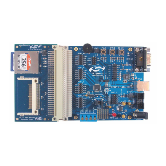
• C8051F340 Target Board
• C8051Fxxx Development Kit Quick-Start Guide
• AC to DC Power Adapter
• USB Debug Adapter (USB to Debug Interface)
• USB Cable
• CD-ROM
2. Hardware Setup Using a USB Debug Adapter
The target board is connected to a PC running the Silicon Laboratories IDE via the USB Debug Adapter as shown
in Figure 1.
1. Connect the USB Debug Adapter to the DEBUG connector on the target board with the 10-pin ribbon cable.
2. Connect one end of the USB cable to the USB connector on the USB Debug Adapter.
3. Connect the other end of the USB cable to a USB Port on the PC.
4. Connect the ac/dc power adapter to power jack P1 on the target board.
Notes:
• Use the Reset button in the IDE to reset the target when connected using a USB Debug Adapter.
• Remove power from the target board before removing the ribbon cable from the target board. Connecting or
disconnecting the cable when the devices have power can damage the device and/or the USB Debug
Adapter.
PC
Notes:The C8051F340 target board has the ability to be powered through the USB cable. To enable the USB-powered mode,
short the pins labeled VBUS and VREGIN on the J8 header. Do not short all 3 pins on the J8 header.
Rev. 0.3 2/14
EVELOPMENT
USB
Cable
Figure 1. Hardware Setup Using a USB Debug Adapter
Copyright © 2014 by Silicon Laboratories
K
U
'
G
IT
SER
S
AC/DC
Adapter
USB Debug Adapter
SILICON LABORATORIES
P1.6
Port 2
Port 1
C 8 0 5 1 F 3 4 x
U I D E
Target Board
PWR
MCU
Port 0
Port 3
Port 4
C8051F34x
Advertisement

Related Manuals for Silicon Laboratories C8051F340


Summary of Contents for Silicon Laboratories C8051F340
- Page 1 • CD-ROM 2. Hardware Setup Using a USB Debug Adapter The target board is connected to a PC running the Silicon Laboratories IDE via the USB Debug Adapter as shown in Figure 1. 1. Connect the USB Debug Adapter to the DEBUG connector on the target board with the 10-pin ribbon cable.
-
Page 2: Software Setup
Once Simplicity Studio is installed, the application itself can be used to install additional software and documentation components to aid in the development and evaluation process. Figure 2. Simplicity Studio The following Simplicity Studio components are required for the C8051F340 Development Kit: 8051 Products Part Support ... - Page 3 2. Click the Create new project link from the welcome screen or go to File Silicon Labs MCU Project. 3. In the Kit drop-down, select C8051F340 Development Kit, in the Part drop-down, select C8051F340, and in the SDK drop-down, select the desired SDK. Click Next. 4. Select Example and click Next.
- Page 4 C8051F34x 3.3. Legacy 8-bit IDE Note: Using the Simplicity Studio tools with the C8051F340 Development Kit is recommended. See section 3. "Software Setup‚" on page 2 for more information. Download the 8-bit software from the website (www.silabs.com/8bit-software) or use the provided installer on the CD-ROM to install the software tools for the C8051F34x devices.
- Page 5 C8051F34x information. 7. Once the form is complete, click the Submit button. An email will be sent to the provided email address with the license activation code. 8. Copy the License ID Code (LIC) from the email. 9. Paste the LIC into the New License ID Code (LIC) text box at the bottom of the License Management window in µVision4.
-
Page 6: Target Board
C8051F34x 4. Target Board The C8051F34x Development Kit includes a target board with a C8051F340 device pre-installed for evaluation and preliminary software development. Numerous input/output (I/O) connections are provided to facilitate prototyping using the target board. Refer to Figure 4 for the locations of the various I/O connectors. - Page 7 4.2. Switches and LEDs Three switches are provided on the target board. Switch RESET is connected to the RESET pin of the C8051F340. Pressing RESET puts the device into its hardware-reset state. Switches P2.0 and P2.1 are connected to the C8051F340’s general purpose I/O (GPIO) pins through headers.
- Page 8 4.5. USB Self-Powered Configuration (J8) The C8051F340 target board can be configured as a self-powered USB device to take power from the USB cable instead of the ac/dc adapter connected at P1. To configure the target boards as a self-powered USB device, short...
- Page 9 J12[15-16]- Install shorting block to connect UART0 CTS (P2.7) to transceiver. 4.8. Analog I/O (P2) Several of the C8051F340 target device’s port pins are connected to the P2 terminal block. Refer to Table 5 for the P2 terminal block connections.
- Page 10 C8051F34x 5. Schematics Rev. 0.3...
- Page 11 C8051F34x Rev. 0.3...
-
Page 12: Document Change List
C8051F34x OCUMENT HANGE Revision 0.1 to Revision 0.2 Removed EC2 Serial Adapter from Kit Contents. Removed Section 2. Hardware Setup using an EC2 Serial Adapter. See RS232 Serial Adapter (EC2) User's Guide. Removed Section 8. EC2 Serial Adapter. See RS232 Serial Adapter (EC2) User's Guide. ... - Page 13 The products must not be used within any Life Support System without the specific written consent of Silicon Laboratories. A "Life Support System" is any product or system intended to support or sustain life and/or health, which, if it fails, can be reasonably expected to result in significant personal injury or death.
Need help?
Do you have a question about the C8051F340 and is the answer not in the manual?
Questions and answers