Advertisement
Quick Links
Chipsmall Limited consists of a professional team with an average of over 10 year of expertise in the distribution
of electronic components. Based in Hongkong, we have already established firm and mutual-benefit business
relationships with customers from,Europe,America and south Asia,supplying obsolete and hard-to-find components
to meet their specific needs.
With the principle of "Quality Parts,Customers Priority,Honest Operation,and Considerate Service",our business
mainly focus on the distribution of electronic components. Line cards we deal with include
Microchip,ALPS,ROHM,Xilinx,Pulse,ON,Everlight and Freescale. Main products comprise
IC,Modules,Potentiometer,IC Socket,Relay,Connector.Our parts cover such applications as commercial,industrial,
and automotives areas.
We are looking forward to setting up business relationship with you and hope to provide you with the best service
and solution. Let us make a better world for our industry!
Contact us
Tel: +86-755-8981 8866 Fax: +86-755-8427 6832
Email & Skype: info@chipsmall.com Web: www.chipsmall.com
Address: A1208, Overseas Decoration Building, #122 Zhenhua RD., Futian, Shenzhen, China
Advertisement

Related Manuals for Silicon Laboratories C8051F310DK-T


Summary of Contents for Silicon Laboratories C8051F310DK-T
- Page 1 Chipsmall Limited consists of a professional team with an average of over 10 year of expertise in the distribution of electronic components. Based in Hongkong, we have already established firm and mutual-benefit business relationships with customers from,Europe,America and south Asia,supplying obsolete and hard-to-find components to meet their specific needs.
-
Page 2: Kit Contents
• CD-ROM 2. Hardware Setup Using a USB Debug Adapter The target board is connected to a PC running the Silicon Laboratories IDE via the USB Debug Adapter as shown in Figure 1. 1. Connect the USB Debug Adapter to the DEBUG connector on the target board with the 10-pin ribbon cable. -
Page 3: Software Setup
C8051F31x 3. Software Setup Simplicity Studio greatly reduces development time and complexity with Silicon Labs EFM32 and 8051 MCU products by providing a high-powered IDE, tools for hardware configuration, and links to helpful resources, all in one place. Once Simplicity Studio is installed, the application itself can be used to install additional software and documentation components to aid in the development and evaluation process. - Page 4 C8051F31x 3.1. Running Blinky Each project has its own source files, target configuration, SDK configuration, and build configurations such as the Debug and Release build configurations. The IDE can be used to manage multiple projects in a collection called a workspace.
- Page 5 C8051F31x 3.3. Legacy 8-bit IDE Note: Using the Simplicity Studio tools with the C8051F310 Development Kit is recommended. See section 3. "Software Setup‚" on page 2 for more information. Download the 8-bit software from the website (www.silabs.com/8bit-software) or use the provided installer on the CD-ROM to install the software tools for the C8051F31x devices.
- Page 6 C8051F31x information. 7. Once the form is complete, click the Submit button. An email will be sent to the provided email address with the license activation code. 8. Copy the License ID Code (LIC) from the email. 9. Paste the LIC into the New License ID Code (LIC) text box at the bottom of the License Management window in µVision4.
-
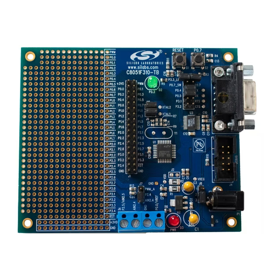
Page 7: Target Board
C8051F31x 4. Target Board The C8051F31x Development Kit includes a target board with a C8051F310 device pre-installed for evaluation and preliminary software development. Numerous input/output (I/O) connections are provided to facilitate prototyping using the target board. Refer to Figure 4 for the locations of the various I/O connectors. Power connector (accepts input from 7 to 15 VDC unregulated power adapter) 34-pin Expansion I/O connector Port I/O Configuration connector... - Page 8 C8051F31x 4.1. System Clock Sources The C8051F310 device installed on the target board features a calibrated programmable internal oscillator which is enabled as the system clock source on reset. After reset, the internal oscillator operates at a frequency of 3.0625 MHz (±2%) by default but may be configured by software to operate at other frequencies. Therefore, in many applications an external oscillator is not required.
- Page 9 C8051F31x 4.3. Expansion I/O Connector (J1) The 34-pin Expansion I/O connector J1 provides access to all signal pins of the C8051F310 device. Pins for +3 V, digital ground and the output of an on-board low-pass filter are also available. A small through-hole prototyping area is also provided.
- Page 10 C8051F31x 4.5. Serial Interface (J5) A RS232 transceiver circuit and DB-9 (J5) connector are provided on the target board to facilitate serial connec- tions to UART0 of the C8051F310. The TX, RX, RTS and CTS signals of UART0 may be connected to the DB-9 connector and transceiver by installing shorting blocks on header J3.
- Page 11 C8051F31x 5. Schematic Rev. 0.7...
- Page 12 C8051F31x OCUMENT HANGE Revision 0.4 to Revision 0.5 Section 1, added USB Debug Adapter and USB Cable. Section 2, changed name from "Hardware Setup" to "Hardware Setup using an EC2 Serial Adapter". Section 2, added 2 Notes bullets. Section 2, removed Note from bottom of page.
- Page 13 The products must not be used within any Life Support System without the specific written consent of Silicon Laboratories. A "Life Support System" is any product or system intended to support or sustain life and/or health, which, if it fails, can be reasonably expected to result in significant personal injury or death.
Need help?
Do you have a question about the C8051F310DK-T and is the answer not in the manual?
Questions and answers