Table of Contents
Advertisement
Quick Links
Installation & Maintenance Instructions
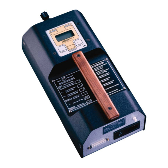
Jerome® J431-x
Mercury Vapor Analyser
Reading Office
Aberdeen Office
Cutbush Park, Danehill, Lower Earley,
Unit 6 Airside Business Park, Kirkhill Industrial Estate,
Reading, Berkshire. RG6 4UT. UK.
Dyce, Aberdeen. AB21 0GT. UK.
Tel: +44 (0)118 9311188
Tel: +44 (0)1224 725999
Email: info@able.co.uk
Email: ab@able.co.uk
Internet: www.able.co.uk
e-procurement: www.247able.com
Registered in England No: 01851002
VAT No: GB 417 2481 61
Advertisement
Table of Contents
Troubleshooting

Related Manuals for Arizona Instrument Jerome J431-x


Summary of Contents for Arizona Instrument Jerome J431-x
- Page 1 Installation & Maintenance Instructions Jerome® J431-x Mercury Vapor Analyser Reading Office Aberdeen Office Cutbush Park, Danehill, Lower Earley, Unit 6 Airside Business Park, Kirkhill Industrial Estate, Internet: www.able.co.uk Reading, Berkshire. RG6 4UT. UK. Dyce, Aberdeen. AB21 0GT. UK. e-procurement: www.247able.com Tel: +44 (0)118 9311188 Tel: +44 (0)1224 725999 Registered in England No: 01851002...
- Page 2 431-X Mercury Vapor Analyzer Operation Manual PROPRIETARY RIGHTS NOTICE This manual contains valuable information and material developed by Arizona Instrument LLC ® for use with the Jerome 431-X Mercury Vapor Analyzer. No part of this manual can be reproduced or transmitted in any form or by any means, electronic, mechanical or otherwise.
-
Page 3: Table Of Contents
Table of Contents FOR THOSE WHO CAN'T READ THE WHOLE MANUAL NOW ........ 5 INTRODUCTION ........................7 PRINCIPLE OF OPERATION ....................8 Zero Air Filter ..........................9 INSTRUMENT OPERATION ....................10 LCD Codes ..........................10 Daily Operations .......................... 11 Sensor Regeneration ........................12 Zero Adjust .......................... - Page 4 Dilution Module Ratio Check ..................... 49 Loading the Dosimeter ........................ 50 Dilution Module Ratio Calculations ................... 51 Analysis with a Dilution Module ....................52 13. APPENDIX C - INTERNAL DIP SWITCH SETTINGS ............. 55 ® 14. APPENDIX D - JEROME COMMUNICATIONS SOFTWARE ........
-
Page 5: For Those Who Can't Read The Whole Manual Now
SHIPPED, YOU SHOULD INSURE IT FOR FULL VALUE. Check for any damage and confirm receipt of all parts on your packing list. Contact Arizona Instrument Customer Service at (800) 528-7411 or (602) 470-1414 if you have any questions. Press the ON button. The display should read 000 in less than one second. - Page 6 Check the voltage setting (110 or 220 VAC) on the back of the instrument. Ensure that it is set to the correct voltage. If the pointer is not aligned to the local voltage, turn the selector to point to the correct voltage. ...
-
Page 7: Introduction
INTRODUCTION ® The Jerome 431-X Mercury Vapor Analyzer is an ambient air analyzer with a range of 0.001 to .999 milligrams of mercury vapor per cubic meter (mg/m Hg). CAUTION: ® The Jerome 431-X is for vapor use only. DO NOT allow the probe or the instrument's intake to be exposed to any liquid, dust or other foreign material. -
Page 8: Principle Of Operation
Applications Ambient air analysis Regulatory compliance Quality control Scrubber efficiency testing Accuracy check for other Mercury Vapor monitors and control systems Mercury Vapor source detection Leak detection Portable Mercury Vapor detection ® The Jerome 431-X can be operated from 100-120 or 200-240 VAC. -
Page 9: Zero Air Filter
The sample air passes through a filter (removing any acidic gases which interfere with the sensor's response to mercury) and is drawn over the gold film sensor. The sensor absorbs the Mercury Vapor. Nine seconds after starting, the sample solenoid bypass closes and the remainder of the sample is drawn through the scrubber filter and the flow system. -
Page 10: Instrument Operation
INSTRUMENT OPERATION LCD Codes LCD CODE EXPLANATION Ready to sample .000 No Mercury Vapor reading 00.0 No Mercury Vapor reading, display in nanograms .8.8.8 Sensor saturated-regeneration needed (refer to page 12) .H.H.H Sensor regeneration in progress (.H.H.H flashes) .L.L.L Re-zero needed (refer to page 13) .P.P.P Power cord required or low line power, <100 VAC (or 200 VAC) (see pages 16 and 17, Changing the Fuse, if .P.P.P remains on after... -
Page 11: Daily Operations
Daily Operations ® Before each day's use of the Jerome 431-X, perform the following steps to verify proper instrument operation: Press the power ON button. The digital meter displays 000. (Disregard the digital meter's initial momentary reading.) ... -
Page 12: Sensor Regeneration
Sensor Regeneration Sensor regeneration is needed to clear the 431-X sensor of any accumulated Mercury Vapor and to prolong the life of the sensor. This simple procedure should be done: At the beginning of the day on which the instrument is to be used. ... -
Page 13: Zero Adjust
Zero Adjust To ensure air entering the instrument is clean, install the zero air filter in the instrument’s intake and sample until the readings stabilize. While pressing the ZERO button, turn the ZERO ADJUST potentiometer (shown at right) using the trimmer tool until the digital meter reads 0. -
Page 14: Sample Mode
Sample Mode This mode, used for standard operation, produces optimum accuracy (±5% at 0.100 mg/m ® with the Jerome 431-X. Press the power ON button. The digital meter displays 000. If the unit is set to display in ng, the digital meter displays 00.0. -
Page 15: Survey Mode
Survey Mode The survey mode takes samples every 3 seconds automatically. Use this mode to locate mercury spills or to assess areas of potentially high mercury concentrations. Sampling in the survey mode is not as accurate. Due to the decreased sample volume, the accuracy of the instrument is reduced to ±... -
Page 16: Operating On Ac Power Or Generator
Operating on AC Power or Generator For stationary use, the 431-X may be operated on AC power. Operating the instrument on AC power at all times eliminates the need for the battery pack and its necessary maintenance. The battery may be unplugged or removed completely whenever the instrument is operating on AC power. -
Page 17: Charging Batteries
Charging Batteries Press the power OFF button. Connect the AC power cord between the 431-X power receptacle and an AC power source. Complete battery recharging takes 14 hours. The 431-X contains a trickle charger so it may be continually plugged into an AC power source without damaging the battery pack. -
Page 18: Maintenance
MAINTENANCE Preventive Maintenance Calendar ® To keep the Jerome 431-X operating at peak performance, follow the maintenance schedule below as a guide. Since maintenance is more a function of application and amount of use rather than time, your requirements may be different from the listed schedule. Call AZI Customer Service at 800-528-7411, 602-470-1414, or e-mail support@azic.com for additional guidance for your environment and operation. -
Page 19: Flow System
Flow System ® The Jerome 431-X's flow system is the crucial link between the sensor and the sample. For the instrument to perform correctly, the flow system must be properly maintained. The user maintainable components of this system are the intake filter (.25 inch fritware), a C/M Filter, two scrubber filters and connecting tubing. -
Page 20: Internal Filters
Internal Filters Replace the internal filters after six (6) months of use, or as needed. Press the power OFF button and unplug the power cord. Remove the two (2) side screws from the intake end of the instrument and open the case. ... -
Page 21: Replacing The Battery Pack
Replacing the Battery Pack Press the power OFF button. Unplug the power cord. Remove the two (2) side screws from the intake end of the instrument and open the case lid. Disconnect the battery connector from the board. ... -
Page 22: Display Nanograms Or Milligrams Per Cubic Meter
Remove the two screws toward the front of the instrument and open the lid. Locate the DIP Switch SW2 at the top of the main circuit board. This is the red on illustrated at right Set SW2 position #1 and #6 as follows. -
Page 23: Calibration
We strongly recommend you take advantage of our calibration and maintenance service at Arizona Instrument. Call Customer Service at (800) 528-7411 or (602) 470-1414 to arrange re- calibration. A certificate of calibration is issued from AZI when your instrument is factory calibrated. -
Page 24: 431-X Troubleshooting
431-X TROUBLESHOOTING Symptom Possible Cause Solution Power Problems Unit does not turn ON. Unit Discharged battery or Recharge battery for a minimum of turns on when power cord is 14 hours. Refer to page 17. plugged in. LCD displays 000 Dead battery. - Page 25 Sampling Problems Airflow is restricted during the Kinks and crimps in the Periodically check the Tygon tubing sensor regeneration cycle, causing Tygon tubing. inside the instrument. Refer to possible permanent damage. page 20. 1. Install zero air filter in intake High erratic results.
- Page 26 False readings, may go to .8.8.8 or Extremely cold or extremely If sampling under these conditions, .L.L.L. warm air sampled into unit. install zero air filter in intake. Sample until display reads 0.003 mg/m3 or less. This equilibrates sensor temperature with the temperature of the sample air stream.
-
Page 27: Jerome ® 431-X Technical Specifications
® JEROME 431-X TECHNICAL SPECIFICATIONS Range 0.001 to 0.999 mg/m Sensitivity 0.003 mg/m Precision 5% relative standard deviation at 0.100 mg/m Accuracy ±5% at 0.100 mg/m Response time-sample mode 12 seconds Response time-survey mode 3 seconds Flow rate 750 ± 50ml/min (0.75 ± .05 liters/min) 100-120 VAC, 50/60 Hz, 1 A, or Power requirements 220-240 VAC, 50/60 Hz, 1 A... -
Page 28: Instrument I/O Interface
Instrument I/O Interface The 431-X I/O port (25 pin D-sub) provides the following functions: Serial data communication Interface type: RS-232C full duplex, DCE Parameters: 1200 Baud, 1 start bit, 8 data bits, 2 stop bits, no parity ... -
Page 29: Potential Interferences
In addition, a special filter designed to remove chlorine gas from the sample stream is available from Arizona Instrument and may be ordered as ®... -
Page 30: Accessories & Maintenance Parts
ACCESSORIES & MAINTENANCE PARTS PART # ITEM DESCRIPTION Y431 0901 431 Accessory Kit (See pictures beginning on page 32) 1400 2002 Probe Tubing Adapter, 1/4” to 1/8” 1400 3010 2300 0001 Trimmer Tool 2600 3039 .25 Fritware 6000 4003 Line Cord, 115 VAC - USA and Canada Alt. - Page 31 ® Jerome Data Logger ® Y990-0169 Includes the Jerome Data Logger and JCS Software Kit. Y990-0175 Personal Dosimeter Kit (110 VAC) Includes the Pocket Pump, two mercury dosimeters, zero air Y990-0176 filter, regeneration cable, (220 VAC) connecting tubing and adaptor. Y990-0168 (with cable) ®...
-
Page 32: Spare Parts
Soft Field Carrying Case 1400 0052 Hand/shoulder case with pockets for accessories. Spare Parts Personal X412 0901 Mercury Dosimeter Stopper A2600 0902 Assembly Z2600 3914 Septum Holder 3200 0011 Septa Syringe A2600 0903 Assembly Syringe Needles, 2600 0022 22 Ga. AZI Customer Service 800-528-7411 or 602-470-1414 Page 32 of 67... - Page 33 1400 2002 Probe 2300 0001 Trimmer 1/8 x 3/16 1300 0031 reducer Battery Pack Z4000 0907 Assembly (115V) Battery Pack Z4000 0908 Assembly (230V) Z2600 3905 Zero air filter Z2600 3928 C/M filter Z2600 3930 Scrubber filter Z2600 3940 Chlorine Filter 990-0193 Ammonia Filter 1400 3010 Tubing adapter Includes mounting hardware...
- Page 34 2600 3039 .25 inch fritware Tygon tubing 2500 3001 1/8" I.D. (1 foot) Tygon tubing 2500 3002 1/16" I.D. (1 foot) 115 VAC IDC battery charger 4000 1011 (Used to charge an uninstalled battery) 230 VAC IDC battery charger 4000 1012 (Used to charge an uninstalled battery)
- Page 35 100-120 VAC 6000 4003 Line Cord 220-240 VAC Alternate – Line Cord for 200-0003 England 220-240 VAC Alternate – Line Cord for 200-0008 Europe 10 to 1 Dilution 990-0225 Module AZI Customer Service 800-528-7411 or 602-470-1414 Page 35 of 67...
-
Page 36: Factory Calibration Service
5100 1012 Spare Fuse ® 6000 1055 Jerome Communication Cable For current prices and delivery information, call AZI Customer Service at (800) 528-7411 or (602) 470-1414. Factory Calibration Service Service includes filter replacement, component testing, and instrument calibration to NIST traceable standards. -
Page 37: Appendix A - 431-X Functional Test Kit
APPENDIX A - 431-X FUNCTIONAL TEST KIT If your application requires frequent verification of instrument functionality, this test will benefit you. If the test results fall within the expected range, you may assume the instrument is functioning properly. THIS IS A FIELD CHECK OF THE FUNCTIONALITY OF THE INSTRUMENT. THIS TEST DOES NOT CALIBRATE THE INSTRUMENT. -
Page 38: Mercury Transfer
Mercury Transfer CAREFULLY pour the mercury into the center of the functional test kit vessel’s opening. ENSURE that no mercury residue is on the outside of the vessel. See the supplier’s Material Safety Data Sheets (MSDS) or call AZI Customer Service at 1-800-528-7411 or 1-602-470-1414 for clean-up instructions. -
Page 39: Replacing Mercury
Replacing Mercury An oxide coating will form on the drop of mercury and will cause lower readings in your testing. Gently swirl the vessel to disturb the outer oxidized surface of the droplet. If this does not restore higher readings, it may be necessary to replace the mercury. ... - Page 40 If the average meter reading is greater than .005, stop here. The instrument may be contaminated. See 431-X TROUBLESHOOTING on page 24. If the average meter reading is less than .005, continue to the next step. Note the temperature of the calibration vessel. ...
-
Page 41: Syringe Technique
Syringe Technique Pull and hold the syringe plunger against the bar-stop. Verify that the black mark on the syringe plunger aligns with the 1cc mark on the syringe barrel. If it does not, the holder assembly must be adjusted. Call AZI customer service at 602-281- 1745 or 800-528-7411 for assistance. -
Page 42: 431-X Temperature Conversion Chart
When the display flashes, release the plunger and allow gravity to feed the mercury vapor into the airstream. If the plunger stops, gently press it completely closed. Remove the syringe needle from the septum. 431-X Temperature Conversion Chart Temperature in °C Digital Meter Response .091 to .123... -
Page 43: Functional Test Troubleshooting
Functional Test Troubleshooting If you don’t achieve good results with the functional test procedure, check the following: Results Solution Typically too high Ensure the calibration vessel temperature is stable. Be sure to inject the Hg vapor ONLY after the display flashes (approximately 2 seconds after SAMPLE is pressed). -
Page 44: Appendix B - Personal Mercury Dosimeter
APPENDIX B - PERSONAL MERCURY DOSIMETER The gold coil personal mercury dosimeter is a unique collection device for mercury vapor. The ® Jerome 431-X Gold Film Mercury Vapor Analyzer and the Personal Mercury Dosimeter determine personal exposure levels and ambient air concentrations, as well as low levels of mercury in natural and stack gases. -
Page 45: Before Sampling With The Dosimeter
Before Sampling with the Dosimeter The personal mercury dosimeter adsorbs mercury vapor over a set period of time. Therefore, before each day's use it is necessary to ensure the dosimeter is mercury free. Perform the following steps to remove any accumulated mercury. ... -
Page 46: Dosimeter Analysis
Dosimeter Analysis NOTE: Wait a minimum of 30 minutes after a sensor regeneration before continuing. Connect the system as shown. Insert the dosimeter's large end in the 431-X's intake and gently tighten the intake tube nut to ensure an airtight seal. ... - Page 47 Perform the following calculation to obtain the mercury concentration in mg/m based on a time weighted average; or alternately, DIP switch #2 can be set to OFF and the digital meter will display nanograms Hg directly (refer to diagram, page 55 ). Working Formula and Units of Measure Meter sponse X ConversionFactor...
-
Page 48: Non-Standard Flow Rates And Dilution Modules
Check the sensor status after each dosimeter analysis. IMPORTANT: To prevent the loss of a sample, perform sensor regeneration as soon as the display shows “- - - -” (four bars). This indicates that the sensor is 75-100 percent saturated. ... -
Page 49: Dilution Module Ratio Check
Dilution Module Ratio Check The 10:1 dilution module was manufactured and calibrated to produce a 10:1 ratio in the sample delivered to the instrument. Over time the ratio may change slightly. To accurately determine the exact dilution offered by the 10:1 dilution module, perform the following tests and calculate the exact dilution ratio. -
Page 50: Loading The Dosimeter
Loading the Dosimeter Connect your pump, dosimeter, septum holder assembly and zero air filter together with 1/8" and 3/16" Tygon™ tubing as shown to the right. Turn on the pump. Inject 10 cc’s of Hg into the septum, 1 cc at a time. -
Page 51: Dilution Module Ratio Calculations
Dilution Module Ratio Calculations Multiply the average obtained for Direct 431-X Readings by 10 (the number of 1 cc injections). Divide this result by the average obtained in the section “Loading the Dosimeter” on page 50. Use the result as the dilution module ratio in your dosimeter analysis. EXAMPLE: Direct 431-X readings 0.102 mg/m... -
Page 52: Analysis With A Dilution Module
Analysis with a Dilution Module NOTE: Wait a minimum of 30 minutes after sensor regeneration before starting this procedure. Connect the system as shown in the figures below. Attach the power cord to the 431-X and plug it into AC power. - Page 53 MR (meter response) total of the two digital meter readings in mg/m conversion factor, a constant which changes the meter response 87.5 ng/mg/m to nanograms of Hg DM dilution module ratio the ratio determined on page 51 pump flow rate (in cc/min) multiplied by sample time (in SV (sample volume) minutes) Sample concentration...
- Page 54 Dosimeter Reference Chart 431-X Expected concentration, related to sample volume and meter response = Indicates the optimum meter response for that concentration with the corresponding volume 431-X reading in mg/m 0.429 0.857 0.086 0.171 0.343 0.686 Estimated 0.05 0.043 0.086 0.171 0.343 0.686...
-
Page 55: Appendix C - Internal Dip Switch Settings
APPENDIX C - INTERNAL DIP SWITCH SETTINGS Main circuit board RED DIP switches (SW2) This is the red DIP switch box located at the top, center of the instrument’s main circuit board. The 431-X provides regulated film heat at both 50 Hz and 60 Hz line frequencies. This also provides two ranges of preset but unregulated film heat (100-120/200-240 volt and 110-130/220-260 volt ranges). -
Page 56: Appendix D - Jerome Communications Software
® APPENDIX D - JEROME COMMUNICATIONS SOFTWARE ® The Jerome Communications Software (JCS) is used with 431-X Mercury Vapor Analyzers that feature the communications configuration option. The JCS allows the user to program the instrument for unattended monitoring and to ®... -
Page 57: Jcs Kit Contents
JCS Kit Contents Jerome ® Communication Software on CD-ROM with security key Jerome ® Communication Cable, AZI P/N 6000 1055 User’s manual System Requirements Jerome ® 431-X with the “Communications Option.” These Jerome ® instruments have a DB-25 connector and related internal hardware and firmware. -
Page 58: Appendix E - Jerome 431-X Option Board
® APPENDIX E - JEROME 431-X OPTION BOARD Proper use of this board requires that the base instrument be fully functional and set correctly for the intended operation. Auto-Zero With the option board installed, the 431-X has a limited auto-zero function. This function cannot be disabled and is transparent to the user. -
Page 59: Timed Regeneration
In some cases, the instrument cannot resume sampling after regeneration. .L.L.L appears on the display when the ZERO button is pressed and the error message “manual bridge adjust needed” is added to the notes column of the JCS text file when the JCS is used. If this problem persists, it may be necessary to re-set the auto-zero. -
Page 60: Auto-Sample
Auto-Sample If a data logger is either not connected or is operating in the manual sampling mode, the following automatic sampling rates may be selected with option board’s SW100 dip switch settings: Dip switch settings Sampling frequency No automatic sampling 5 minutes 15 minutes 30 minutes... -
Page 61: Connection And Setup
® Jerome 431-X instruments shipped after early 1995 are capable of providing 0-2 volts analog output. Instruments shipped before that time can be upgraded by a firmware update and adjustment. Instruments that are capable of 0-2 volt output can be upgraded to the 4-20 mA output with the addition of an option board upgrade. - Page 62 The 4-20 mA passive receivers do not contain a voltage source to power the loop current. They require the addition of a separate isolated power supply. Typically a supply that delivers 15 to 20 volts DC at 50 mA is sufficient. Wire these as in Figure 3.
-
Page 63: Fresh Air Solenoid
Fresh Air Solenoid An external three-way solenoid can be used to provide fresh air or conditioned air during sensor regeneration. This may be necessary if the sample stream lacks molecular oxygen. A low current six volt DC solenoid, connected between pins 19 and 11 of the 25 pin rear panel connector, will be energized during the regeneration cycle if the option board SW100 switch 6 is placed in the OFF position. -
Page 64: Dc Power Operation
DC Power Operation Instruments with the 431-X option board modification can be used with any +12 VDC source for continuous operation, if the AZI Power Inverter Kit, P/N Y031 0902 is installed along with the option board. To preserve the life of the DC power source, usually a car or truck battery, the power inverter will switch on automatically to supply the AC necessary for regeneration only. - Page 65 Ensure that the inverter’s power switch is in the “OFF” position. LEAVE the power switch in the “OFF” position at all times. The interface board will activate the inverter when necessary. If the inverter power switch is placed in the “ON” position, it will cause a continuous drain on the external 12-volt power system.
-
Page 66: Warranty
WARRANTY ® Arizona Instrument LLC (seller) warrants to buyer that Jerome products delivered pursuant to this agreement shall, at the time of delivery, and for a period of one (1) year. Thereafter (the Internal Battery Pack, where applicable, is warranted for a period of ninety [90] days only), to be free from defects in material or workmanship and shall conform to seller's specifications or such other specifications as seller has agreed to in writing. - Page 67 AZI are all registered trademarks of Arizona Instrument LLC. Instrument firmware is copyright protected. All specifications subject to change without notice. Copyright 1990-2011 Arizona Instrument LLC. All Rights Reserved. ® Resisorb is a registered trademark of Avantor Performance Materials.
Need help?
Do you have a question about the Jerome J431-x and is the answer not in the manual?
Questions and answers