Table of Contents
Advertisement
USER MANUAL
®
®
COMPUTRAC
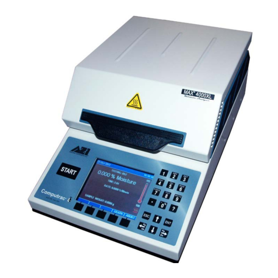
MAX
4000/4000XL
MOISTURE ANALYZER
Firmware Rev 1.6X
December 2017
ARIZONA INSTRUMENT LLC
3375 N Delaware Street | Chandler, AZ 85225 USA
800.528.7411 | 602.470.1414 | f 602.281.1745
www.azic.com
Email:
General –
azi@azic.com
International –
intl@azic.com
Customer Service –
support@azic.com
AZI P/N 700-0111-L
Last update December 2017
Advertisement
Table of Contents

Related Manuals for Arizona Instrument COMPUTRAC MAX 4000


Summary of Contents for Arizona Instrument COMPUTRAC MAX 4000
- Page 1 USER MANUAL ® ® COMPUTRAC 4000/4000XL MOISTURE ANALYZER Firmware Rev 1.6X December 2017 ARIZONA INSTRUMENT LLC 3375 N Delaware Street | Chandler, AZ 85225 USA 800.528.7411 | 602.470.1414 | f 602.281.1745 www.azic.com Email: General – azi@azic.com International – intl@azic.com Customer Service –...
- Page 2 ® Computrac 4000 / 4000XL PROPRIETARY RIGHTS NOTICE This manual contains valuable information developed by Arizona Instrument LLC for use ® with the Computrac line of moisture analyzers. No part of this manual can be reproduced or transmitted in any form or by any means, electronic, mechanical, or otherwise.
-
Page 3: How To Use This Manual
4000 / MAX 4000XL. §16 WARRANTY page 104 - This section details Arizona Instrument’s warranty policy. All section numbers, titles and page numbers in BOLD in this manual are hyperlinks and can be clicked to simplify navigation within the PDF version of the manual. The BACK button found in most PDF software programs is also very helpful when navigating using the hyperlinks. -
Page 4: Table Of Contents
TABLE OF CONTENTS 1. HOW TO USE THIS MANUAL -------------------------------------------------------------------- 3 2. TABLE OF CONTENTS ---------------------------------------------------------------------------- 4 3. WARNINGS AND SAFETY INFORMATION -------------------------------------------------- 6 4. PACKING AND SHIPPING INSTRUCTIONS ------------------------------------------------- 9 5. INTRODUCTION ------------------------------------------------------------------------------------ 11 5.1. Hardware ..................... 12 5.2. Instrument Models .................. - Page 5 8.3.2.A View Calibration Report ............65 8.3.2.B Verification Setup ............... 66 8.3.2.C Calibration Module Setup ........... 66 8.3.2.D Perform Calibration ............67 8.3.2.E Perform Verification ............68 8.3.2.F Calibration Reminder Setup ..........69 8.4. Setup Menu ....................69 8.4.1 Printer Setup ................... 70 8.4.2 Report Setup ...................
-
Page 6: Warnings And Safety Information
WARNINGS AND SAFETY INFORMATION ® The MAX 4000 moisture analyzer complies with the Underwriter Laboratories Inc. standards and European Council Directives for Electrical Equipment for Laboratory Use, ® electromagnetic compatibility, and the stipulated safety requirements. The MAX 4000 and its accessories pass Class A emissions. However, improper use or handling of the instrument can result in damage to the equipment and/or injury to personnel. - Page 7 “oven cleaners” will damage the case and heater housing of the MAX 4000. • Before using any cleaning or decontamination method except those recommended by Arizona Instrument, check with AZI Customer Service to ensure that the proposed method will not damage the equipment. • The outside housing of the MAX ®...
- Page 8 ENVIRONMENTAL CONDITIONS • STORAGE AND SHIPPING Temperature should be between 0 °C and +40 °C (+32 °F and +104 °F). Relative Humidity should be between 10% and 80%. • OPERATIONAL CONDITIONS – INDOOR USE. Optimum results will be achieved when the instrument is set on a smooth, level, non-vibrating surface in a non-condensing, non-explosive environment of 0 - 40 ºC at 50% relative humidity or 0 - 30 ºC at 80% relative humidity.
-
Page 9: Packing And Shipping Instructions
PACKING AND SHIPPING INSTRUCTIONS IMPORTANT Movement, handling, and packaging of the instrument must be done with ® EXTREME CARE to avoid permanent, expensive internal damage. The MAX 4000 uses a delicate and very sensitive electronic force balance to measure small weights and weight losses. - Page 10 REPACKAGING FOR SHIPMENT • Call AZI Customer Service for Return Material Authorization (RMA) information prior to returning an instrument. • Boxes and packing materials are available from AZI for all shipments. • Pack the MAX ® ® ® 4000 in a Computrac 4000 shipping container.
-
Page 11: Introduction
• Programming is through the front panel keypad with a user friendly menu system. • A color LCD that is easy to read and provides color graphing. • Arizona Instrument's pioneering prediction method that can automatically end a test to provide accurate results in the shortest possible time. -
Page 12: Hardware
• A User Login function that, if activated, can be used to restrict access to calibration functions and instrument and test configuration options except by authorized users, preventing unwanted changes to operating parameters. When User Login is active on ® the MAX 4000XL, a user is required to login prior to testing, and the user name is recorded with each test result. -
Page 13: Instrument Models
5.2. Instrument Models ® ® There are 2 different instrument models in the MAX 4000 series, the MAX 4000 and the ® 4000XL, which have various feature differences, as detailed below. Throughout ® ® ® this manual, MAX 4000 is used to refer to both the MAX 4000 and the MAX 4000XL when describing common features or functionality. -
Page 14: Inventory & Accessories
5.4. Inventory & Accessories Carefully unpack the instrument and locate the following items: Part Name AZI Part Number ® 4000 MAX-4000 / ® 4000XL MAX-4000XL Pan Support Assembly 600-0152 Accessory Kit: Y990-0209 Line Cord, 110 VAC 200-0002 or Line Cord, 220 VAC (Europe) 200-0233 or Line Cord, 220 VAC (UK) 200-0234... -
Page 15: Instrument Setup
INSTRUMENT SETUP Review and perform all necessary setup steps in section 6 (including its subsections). After setting up the instrument, complete the following three items before testing any samples with the instrument: • Perform a balance span calibration (See section 8.3.1.B Perform Span Calibration on page 60). -
Page 16: Interior Of Test Chamber & Pan Support
6.2. Interior of Test Chamber & Pan Support CAUTION - Do not, at any time, attempt to spin the pan support as it may result in damage to the force balance. Avoid excess pressure on the pan support from the top or sides, which can damage the force balance. - Page 17 For best results, AZI recommends that the instrument is provided with its own DEDICATED electrical power outlet. Do not put it on a circuit with motors, blenders, heaters, coolers, grinders, or other high current electrical devices. ® The power source outlet that is used by the MAX 4000 MUST BE GROUNDED.
-
Page 18: User Interface Operation
6.4. User Interface Operation • After power up, the Main Test screen shown below appears. (It may be necessary to press the [ESC] key to clear any calibration reminders). Soft Keys The keypad button functions are as follows: • [START] - Begins a test using the currently selected Test Program. •... -
Page 19: Contrast Adjustment
To begin editing an item either: • Press [ENT] to edit the existing value. • Press an Alphanumeric or Numeric key to overwrite the existing value with a new value. Typical keys during item editing are: • Left and Right Arrow Keys – Move the cursor one position left or right. •... -
Page 20: Back Panel Connections
6.6. Back Panel Connections In addition to the AC power connection, these connections are also available from the back panel of the instrument: • RJ-45 Ethernet Connection (marked ETHERNET) ® o The Ethernet port is used primarily to connect the MAX 4000XL to a Local Area Network (LAN) for use with the optional Web Server. -
Page 21: Connecting A Usb Printer
6.7. Connecting a USB Printer Two optional graphics capable printers are available from AZI: • Color Printer Kit AZI P/N: Y990-0212 • Black and White Mini-Printer Kit AZI P/N: Y990-0252 The printers connect to the USB Type A / Host port (marked USB) on the back panel. Test Programs, Test Results and graphs, and calibrations can be printed. -
Page 22: Connecting A Usb Drive
6.8. Connecting a USB Drive If you wish to monitor testing using a USB drive (AZI P/N: 990-0241), one can be ® connected to the USB Type A / Host port (marked USB) on the back of the MAX 4000. For best results, use AZI Flash Drives (AZI P/N: 990-0241) that have been validated for ®... -
Page 23: Usb Driver Setup
6.9.1 USB Driver Setup ® Before using the computer to receive information from the MAX 4000 through the USB port, the USB driver must be installed on the PC. The USB driver is on the CD with this manual and on the Drivers page of the AZI website at http://www.azic.com. The driver ®... - Page 24 ® ® Windows may display a message regarding Windows Security or a message indicating ® that the driver has not passed Windows Logo Testing. The driver being installed is a ® generic Communications Port driver that is part of Windows (usbser.sys), so it is safe to ignore this warning.
- Page 25 • On earlier versions of Windows ® , additional steps are necessary to complete the installation, and the New Hardware Wizard will start automatically. The following ® pictures and descriptions apply to a Windows XP installation. • If the following dialog box appears, DO NOT connect to Windows ®...
- Page 26 • Select “Install the software automatically”, and click Next ® Again Windows may display a message indicating that the driver has not passed ® Windows Logo Testing. This driver being installed is a generic Communications Port ® driver that is part of Windows (usbser.sys), so it is safe to ignore this warning.
- Page 27 ® Windows will copy a file and finish the wizard. • Click Finish. ® Windows will then indicate that the driver has been successfully installed AZI Sales/Customer Service 800-528-7411 or 602-470-1414 or support@azic.com Page 27 of 105...
-
Page 28: Connecting A Usb Keyboard
6.10. Connecting a USB Keyboard An optional keyboard is available from AZI (AZI P/N: 990-0230) that allows easier text entry. It connects to the USB Type A / Host port (marked USB) on the back panel. The keyboard can be used as a substitute for the alphanumeric keypad, and the arrow, [ESC] and [ENT] keys, and the keyboard function keys F1F5 can be used to activate the soft keys. - Page 29 Install the kit: • Open the lid and remove the plug that is centered in the heater ring. • Install the air diffuser and seal into the opening that was created by the plug removal. Caution – Tighten to finger tight only to prevent breakage. •...
-
Page 30: Nitrogen Control Module
6.12. Nitrogen Control Module The Nitrogen Control module (AZI P/N: Y990-0214) is an optional accessory that is used in conjunction with the Nitrogen Purge Kit to conserve nitrogen. The module turns on nitrogen to the instrument prior to a test and turns off the nitrogen after a test. - Page 31 The module has two LEDs for informational purposes: • The GREEN LED on the right: Solid Green indicates good pressure and nitrogen not currently flowing. Blinking Green indicates good pressure and nitrogen currently flowing. • The RED LED on the left indicates inadequate pressure. The trigger pressure for the module has been factory set to 3 psi +/- 0.2 psi.
-
Page 32: Bar Code Reader
6.13. Bar Code Reader An optional bar code reader (AZI P/N: 990-0231) is available from AZI that allows rapid ® data entry. Alphanumeric data can be entered into the MAX 4000 using the instrument keypad, a USB keyboard, or, if the data is in a bar code format, by using the bar code reader. -
Page 33: Installing & Removing The External Filter
6.14. Installing & Removing the External Filter An optional External Filter (AZI P/N: 800-0071) is available to keep dust and other particulates from entering the interior of the instrument. If the filter is being used, it should be inspected regularly for debris build-up and replaced when dirty. The filter can be installed and removed without placing the instrument on its side. -
Page 34: Moisture Analysis Testing
MOISTURE ANALYSIS TESTING ® ® The Computrac Series loss-on-drying moisture analysis system takes advantage of leading edge technology to reduce test times and increase precision over standard vacuum oven or convection oven drying procedures. Prior to testing, a Test Program is created with the parameters to be used for testing the sample. - Page 35 The microprocessor monitors the sample's weight loss during the entire testing process. Simultaneously, if using the Predict ending criteria, the microprocessor is predicting a final moisture concentration based upon the sample's rate of weight loss compared to the exponential portion of a standard drying curve. Testing continues until the predicted moisture concentration agrees within a certain percentage of the actual moisture concentration appearing on the display.
-
Page 36: Performing A Test
7.1. Performing a Test ® A Test Program for your material must be developed prior to using the MAX 4000 for production testing: • See section 8.1 Test Programs on page 41 for guidance setting up a Test Program. This section helps you determine the proper test temperature, ending criteria, sample size, and other parameters. - Page 37 • The instrument will tare (zero out) the pan. This will occur instantly if the lid has been closed and the balance is stable. • Open the lid and quickly load the sample, taking care to evenly distribute it across the entire pan surface in a thin layer to get the fastest and most accurate results.
- Page 38 • Close the lid, and the instrument weighs the sample. • The test proceeds to dry the sample. For a WEIGHT test only, immediately after the instrument weighs the sample, gently open the lid, carefully remove the 3-gram weight, and gently close the lid.
-
Page 39: Preparing Granular And Powdery Samples
7.2. Preparing Granular and Powdery Samples ® The MAX 4000 can be used to test a wide range of products from finely ground, low-moisture powders to high-moisture slurries. For best results, the sample should be of a uniform particle size distributed evenly over the sample pan. If sample material is collected into a jar or sampling bag, shake the jar or bag to produce a more thorough mixture. -
Page 40: Main Menu
MAIN MENU ® Pressing the MENU soft key on the Main Test screen provides access to the MAX 4000 menu system. To get here, press: [MENU] The first and second levels of the menu system are shown below, and are explained in detail in this section of the manual. -
Page 41: Test Programs
8.1. Test Programs Test Programs are test parameter sets. They are sequentially numbered from 1 to the total number of programs entered into the instrument. The figure below shows program 1 selected, as indicated by the yellow arrow. The 1/20 in the upper right hand corner indicates that a total of 20 test programs have been defined and the blue cursor bar is on number 1 out of 20. - Page 42 Lift compensation amount ® LINK Indicates if this Test Program is linked to the next one (MAX 4000XL) EC MODE Ending Criteria COMPUTRAC MAX 4000 TEST PROGRAM REPORT COMPANY: AZI Preferred Customer INSTRUMENT #: 400000 —————————————————————————————————————————————————————————————————————————————— # ID LINK EC MODE ——————————————————————————————————————————————————————————————————————————————...
-
Page 43: Sample Name
A Test Program may be edited by moving the cursor to the desired program and pressing the [ENT] key. There are 8 categories of test parameters for each Test Program, as shown, each explained in more detail in the following pages. -
Page 44: Temperatures
8.1.2 Temperatures The temperature parameters control the test result, speed, and repeatability. If the moisture of the sample material is known, as determined by a reference ® method, the MAX 4000's temperature can be adjusted until test results correlate with the established moisture concentration. - Page 45 To get here, navigate: [MENU]TEST PROGRAMS[ENT] to edit a programTEMPERATURES The following options are available: • TEST TEMPERATURE – Set to a value that correlates well to the reference method and gives good test times and repeatability. The maximum test temperature is 225 ºC ®...
-
Page 46: Ending Criteria
8.1.3 Ending Criteria To get here, navigate: [MENU]TEST PROGRAMS[ENT] to edit a programENDING CRITERIA The ending criterion is used by the instrument to automatically end a test. This feature makes it unnecessary for the operator to monitor the instrument while it is performing a test. -
Page 47: Sample Size Options
Some samples contain more than one volatile material, such as nylon resins with large amounts of unpolymerized material (Caprolactam). In these cases, the rate will fall to some fixed value when all the moisture has evaporated but while the monomer is still evaporating. - Page 48 The available options are: • SAMPLE SIZE – Set as discussed above. • SAMPLE WINDOW – Set the allowable sample size tolerance. A smaller tolerance produces more repeatable results, but makes it more difficult to load a sample. Generally, pick a window size ≤ 10% of SAMPLE SIZE and less than 1g. •...
-
Page 49: Tare Options
8.1.5 Tare Options To get here, navigate: [MENU]TEST PROGRAMS[ENT] to edit a programTARE OPTIONS The following options are available: • PAN TARE records the empty pan weight after ensuring that its weight is sufficiently stable over a programmable period of time. Pan Tare continues until the weight is found stable (≤... - Page 50 • SAMPLE TARE waits a fixed time after lid closure and records the starting sample weight. Obtaining an accurate Sample Tare is crucial for low moisture samples. The following options are available: High Volatile is used for high volatile materials that evaporate during the Sample Tare.
-
Page 51: Result Display Options
8.1.6 Result Display Options To get here, navigate: [MENU] TEST PROGRAMS[ENT] to edit a programRESULT DISPLAY OPTIONS Standard or custom equations can be employed by the instrument to calculate results. Custom equations are usually used in linked ® tests (available only on the MAX 4000XL) and other tests where industry specific calculations are needed. - Page 52 Standard algebraic rules for order of operations are used, so multiplication and division are performed prior to addition and subtraction. Use parentheses to override algebraic precedence. Examples of normal tests: % Moisture = (1 - W ) * 100. FINAL INITIAL ...
-
Page 53: Lift Compensation
8.1.7 Lift Compensation To get here, navigate: [MENU]TEST PROGRAMS[ENT] to edit a programLIFT COMPENSATION Programmable lift compensation is a ® feature found only in Computrac instruments. It is included because of heated air currents in the oven chamber that apply lift to the sample pan. This causes a falsely high apparent weight loss. -
Page 54: Linked Test Options
8.1.8 Linked Test Options To get here, navigate: [MENU]TEST PROGRAMS[ENT] to edit a programLINKED TEST OPTIONS Linking Test Programs enables multiple adjoining programs to run sequentially as one test, changing temperatures, ending criteria, times, etc. between test segments. This feature is only available ®... -
Page 55: Test Results
8.2. Test Results To get here, navigate: [MENU]TEST RESULTS The TEST RESULTS item allows access ® to past Test Results. On the MAX 4000XL, up to 1,000 results and 100 graphs can be stored before the oldest is ® overwritten. The MAX 4000 only stores 2 Test Results and has no Test Graphs. - Page 56 The analysis is performed using the following formulas that are available on many hand calculators: ∑ MEAN (average) = ( Σ SD (standard deviation) = × RSD (relative standard deviation) expressed as percentage = MEAN • [SEL ALL] – Selects all of the Test Results stored in the instrument. The [DELETE], [ANALYZE], and [PRINT] soft keys can then be used to delete, perform statistical analysis on or print all of the Test Results.
-
Page 57: Graph
8.2.1 Graph ® Available only on the MAX 4000XL. Pressing the [GRAPH] soft key from the Main Test screen or when viewing Test Results brings up the test graph. The [RESULT], [TEMP], [PREDICT], and [RATE] soft keys allow their specific curves to be removed from or added to the graph. -
Page 58: Calibration Menu
8.3. Calibration Menu To get here, navigate: [MENU]CALIBRATION MENU The calibration menu provides access to the balance and heater calibration routines. 8.3.1 Balance Calibration Menu To get here, navigate: [MENU]CALIBRATION MENUBALANCE CALIBRATION MENU Span calibration is used when setting up the instrument in a new location. -
Page 59: A View Calibration Report
8.3.1.A View Calibration Report To get here, navigate: [MENU]CALIBRATION MENUBALANCE CALIBRATION MENU VIEW CALIBRATION REPORT VIEW CALIBRATION REPORT displays the span calibration (and the optional ® linearity verification on the MAX 4000XL). The report includes the information on both screens shown here and can be printed with the [PRINT] soft key on either screen. -
Page 60: B Perform Span Calibration
8.3.1.B Perform Span Calibration To get here, navigate: [MENU]CALIBRATION MENUBALANCE CALIBRATION MENU PERFORM SPAN CALIBRATION Span calibration should be done: • Immediately after initial setup and 60-minute warm-up from cold start. • Whenever the instrument is moved. • Whenever a problem is suspected. •... -
Page 61: C Linearity Verification Setup
8.3.1.C Linearity Verification Setup To get here, navigate: [MENU]CALIBRATION MENUBALANCE CALIBRATION MENU LINEARITY VERIFICATION SETUP ® If you are using a MAX 4000XL, linearity verification can be performed if desired. With a few exceptions for certain industries, this feature is not generally used. -
Page 62: D Perform Linearity Verification
8.3.1.D Perform Linearity Verification ® Available only on the MAX 4000XL. Linearity verification should be done as dictated by your quality policy. Performing the verification: • Press the [PROGRAM] soft key, highlight the (Factory) IDLE Test Program, press [ENT], then press [ESC]. -
Page 63: E Span Calibration Reminder Setup
8.3.1.E Span Calibration Reminder Setup To get here, navigate: [MENU]CALIBRATION MENUBALANCE CALIBRATION MENU SPAN CAL REMINDER SETUP A span calibration reminder prompt is available to automatically remind you to run the balance span calibration at the interval dictated by your policies or procedures. - Page 64 Before performing Temperature Calibration: • Navigate [MENU]SETUP MENUPRINTER SETUP. • Verify that OUTPUT TO COMPUTER is set to No. Change it to No if necessary. • Press [ESC] until back at the Main Menu. Since the TCI port can also be used to output data to a computer, in order to ensure communication between the instrument and the TCI, data output through this port must be turned off during temperature calibration.
-
Page 65: A View Calibration Report
8.3.2.A View Calibration Report To get here, navigate: [MENU]CALIBRATION MENUTEMPERATURE CALIBRATION MENU VIEW CALIBRATION REPORT View Calibration Report shows the last calibration, last verification, and the Temperature Calibration Kit information. The report can be printed with [PRINT], but be sure to disconnect the TCI from the instrument’s TCI port prior to printing any reports. -
Page 66: B Verification Setup
8.3.2.B Verification Setup ® Available on the MAX 4000XL only To get here, navigate: [MENU]CALIBRATION MENUTEMPERATURE CALIBRATION MENU VERIFICATION SETUP Verification Setup allows customization of the temperature verification step that is performed after the temperature calibration. The following options are available: •... -
Page 67: D Perform Calibration
8.3.2.D Perform Calibration ® Available on the MAX 4000XL only To get here, navigate: [MENU]CALIBRATION MENUTEMPERATURE CALIBRATION MENU PERFORM CALIBRATION This selection performs the temperature calibration (and auto verification if ® enabled) of the MAX 4000XL when the Temperature Calibration Kit is connected. Performing the calibration: •... -
Page 68: E Perform Verification
8.3.2.E Perform Verification ® Available on the MAX 4000XL only To get here, navigate: [MENU]CALIBRATION MENUTEMPERATURE CALIBRATION MENU PERFORM VERIFICATION This selection performs the temperature ® verification of the MAX 4000 when the Temperature Calibration Kit is connected. Performing the verification: •... -
Page 69: F Calibration Reminder Setup
8.3.2.F Calibration Reminder Setup ® Available on the MAX 4000XL only To get here, navigate: [MENU]CALIBRATION MENUTEMPERATURE CALIBRATION MENU CALIBRATION REMINDER SETUP A temperature calibration reminder prompt is available. The following options are available: • ENABLE turns on/off the reminder. The factory default setting is No (off). -
Page 70: Printer Setup
8.4.1 Printer Setup To get here, navigate: [MENU]SETUP MENUPRINTER SETUP PRINTER SETUP allows the configuration of data output to a computer, printer or USB drive. Graphics are not sent to the computer or USB drive, only to the printer. The following options are available: •... -
Page 71: A Report Control Options
8.4.2.A Report Control Options To get here, navigate: [MENU]SETUP MENUREPORT SETUPREPORT CONTROL OPTIONS Report control options determine how often during a test a report is generated and sent to the printer, computer or drive. The following options are available: • REPORT ENABLED enables a final report after a test and an optional progress report during a test, as explained in REPORT START below. -
Page 72: B Report Items To Print
8.4.2.B Report Items to Print To get here, navigate: [MENU]SETUP MENUREPORT SETUPREPORT ITEMS TO PRINT Test Results consist of many pieces of information that may or may not be useful in your application. To avoid producing a report with more data than is required, you can choose which items are printed on the report. -
Page 73: Date/Time Setup
8.4.3 Date/Time Setup To get here, navigate: [MENU]SETUP MENUDATE/TIME SETUP Use this function to change the time at initial setup or when changing for daylight savings time. Time is in a 24-hour format. An internal battery maintains the correct time and date when the power is off. If an “RTC Battery Failure”... - Page 74 The following options are available: • NAME & PASSWORD are used to restrict access to the instrument over the intranet. When using IE enter NAME for the User name and enter PASSWORD for the Password to gain access to the instrument. •...
-
Page 75: Misc Options
8.4.5 Misc Options To get here, navigate: [MENU]SETUP MENUMISC OPTIONS The following options are available: • LOT NUMBER - If enabled, starting a test brings up the ENTER LOT NUMBER AND PRODUCT ID screen, shown below. These alphanumeric entries may be used to insert the lot designation and unique product identification into reports. -
Page 76: Nitrogen Control Module
If DISPLAY LOW SAMPLE LOAD is enabled, screens similar to the one below will be displayed during sample loading. In this example, the target sample size is 5g and the sample window is 0.3g. The initial LOAD SAMPLE screen (below left) shows a value of 4.4g, which is (Sample Size –... -
Page 77: Login Setup
8.4.7 Login Setup To get here, navigate: [MENU]SETUP MENULOGIN SETUP This menu allows the setup of user logins. If User Login is active, access to calibration and configuration options can be restricted to authorized users. When active on the ® 4000XL, users are required to login prior to testing and the user name is recorded with each test result. - Page 78 • A standard user that is not a Calibration User or Configuration User has the ability to perform tests and view data and reports, but is not able to modify any settings or parameters, perform any calibrations or delete any test results. •...
-
Page 79: Special Features
8.4.8 Special Features To get here, navigate: [MENU]SETUP MENUSPECIAL FEATURES This menu is used to enable optional features for the instrument, such as the Web Server, and also shows what features are active. If you purchase one of these features, you will be given an access code to enable or disable the feature. -
Page 80: Parameter Expert
8.6. Parameter Expert ® Available on the MAX 4000XL only To get here, navigate: [MENU]PARAMETER EXPERT MENU The Parameter Expert (PE) assists a user through the development of a Test Program. 8.6.1 Develop New Test Program To get here, navigate: [MENU]PARAMETER EXPERT MENU... - Page 81 PE can be exited and reentered, and PE remembers the previous tests, so development can be continued where it was previously stopped. The tests performed so far can be viewed in the TEST RESULTS list. The PE tests are prefixed with ;...
- Page 82 • Next, PE explains the process: Multiple tests are run at various temperatures to find an optimum ending criteria. At lower temperatures, the tests are slower. If it looks like the test will not end in a reasonable time, the test is stopped and a higher temperature is used on the next test.
-
Page 83: Optimize Existing Test Program
8.6.2 Optimize Existing Test Program To get here, navigate: [MENU]PARAMETER EXPERT MENU OPTIMIZE EXISTING TEST PROGRAM Parameter Expert (PE) can optimize an existing Test Program by allowing the user to slightly change the test temperature while PE determines the proper ending criteria. A higher test temperature improves test speed while a lower test temperature improves test repeatability. - Page 84 PE is ready to perform a single test to determine the proper rate ending criteria. After running the single test, optimization is complete, and the Test Program is automatically updated and ready for use. AZI Sales/Customer Service 800-528-7411 or 602-470-1414 or support@azic.com Page 84 of 105...
-
Page 85: Sample Foils
8.7. Sample Foils To get here, navigate: [MENU]SAMPLE FOILS This begins the process of weighing and storing foil weights up to a maximum of 50 unique foils. The foils are weighed before the sample is applied. After weighing, the foils are used in paint processes where the paint is sprayed onto the foil as the end product is ®... -
Page 86: Audit Log
• After the foil is weighed and the lid is opened, the weight of the foil is given. • Press [ENT] to begin editing, then enter the identifying NAME for this foil. Duplicate names are allowed. When done editing, press [ENT] again. •... -
Page 87: Web Server
WEB SERVER ® Optional and available on the MAX 4000XL only ® An optional Web Server can be purchased for the MAX 4000XL, which allows the ® instrument to be accessed from your local area network (LAN) or intranet by a Windows ®... -
Page 88: Calibration Report
9.1. Calibration Report The calibration report is viewed by selecting CALIBRATION REPORT in the left bar. This report is a combination of the balance and temperature calibration reports. The report can be downloaded to the PC as an HTML file. AZI Sales/Customer Service 800-528-7411 or 602-470-1414 or support@azic.com Page 88 of 105... -
Page 89: Lcd View
9.2. LCD View Selecting LCD VIEW in the left bar allows remote monitoring of the instrument. AZI Sales/Customer Service 800-528-7411 or 602-470-1414 or support@azic.com Page 89 of 105... -
Page 90: Test Programs
9.3. Test Programs Test Programs are viewed by selecting TEST PROGRAMS in the left bar. Test Programs can be downloaded from the instrument to the PC or can be uploaded to the instrument ® from the PC. Thus, Test Programs can be retrieved from one MAX 4000XL instrument and saved to another. -
Page 91: Test Results
9.4. Test Results Test Results can be viewed by selecting TEST RESULTS in the left bar. Test Results cannot be modified or deleted through the Web Server; data can only be deleted at the instrument. Test Results are saved in a comma-separated format, which can be read by Microsoft ®... -
Page 92: Audit Log
9.5. Audit Log ® Available on the MAX 4000XL only. The Audit Log is viewed by selecting AUDIT LOG in the left bar. The log can be downloaded to the PC as an HTML file. See section 8.8 Audit Log on page 86 for more details on the Audit Log. -
Page 93: 10. Performance Verification
10. PERFORMANCE VERIFICATION Periodic checks of the system are recommended to verify proper system operation. These periodic checks will satisfy some quality assurance requirements as specified in your quality assurance/control policy. A log is recommended, either hand written or computer managed, which will record the weight test results, sodium tartrate test results, and retained samples’... -
Page 94: Sodium Tartrate Test
10.2. Sodium Tartrate Test The (Factory) TARTRATE test verifies the heater and force balance operation. Sodium tartrate dihydrate is a chemical with a known moisture content that releases moisture at temperatures greater than 120 ºC. Because of its consistent moisture content, sodium tartrate is used as a standard in moisture measurement using oven or titration methods. -
Page 95: Retained Samples
10.3. Retained Samples The weight test and the sodium tartrate test are usually sufficient to satisfy industry guidelines for quality control in moisture measurement. Some additional checks can be performed using replicate testing of retained samples. Retained samples, when stored under airtight conditions, should maintain moisture levels for long periods. -
Page 96: Balance Shaft Check
11.2. Balance Shaft Check Perform the following: • Clean the heat chamber before performing this check (See section 11.1 Heat Chamber on page 95). This keeps debris from falling into the balance shaft. • Turn the instrument off. • Use the supplied tweezers to remove the pan support; place the tweezers’ tips under the pan support and pry the pan support straight up and out of the balance stem. -
Page 97: Pan Support Cleaning
• Use the supplied tweezers to remove the pan support; place the tweezers’ tips under the pan support and pry the pan support straight up and out of the balance stem. Be careful; excess force on the balance can result in costly repairs. •... -
Page 98: Lithium Battery Replacement
11.5. Lithium Battery Replacement If the clock fails to keep time when the instrument is turned off, the battery on the main control board is likely depleted. The battery is not user replaceable. Contact AZI Customer Service for further details and information. 12. -
Page 99: 13. Test Result Problems
SYMPTOM DIAGNOSIS REMEDY Instrument will not Test chamber temperature Allow system to stabilize. tare fluctuates/changes Dirt in heat chamber or under Clean instrument. See section pan support 11.1 Heat Chamber on page 95. Debris in balance shaft See section 11.2 Balance Shaft Check on page 96. - Page 100 SYMPTOM DIAGNOSIS REMEDY Moisture result Temperature too low Increase temperature. too low or solids See section 8.1.2 Temperatures on result too high page 44 or call AZI for assistance. Sample size too small or too Adjust sample size. large See section 8.1.4 Sample Size Options on page 47.
- Page 101 14. APPENDIX A: SAVING & LOADING TEST PROGRAMS To save a copy of any or all of the Test Programs to a USB drive. • Insert the USB drive in the corresponding port of the MAX ® 4000 and confirm that the USB drive icon has appeared in the lower left corner of the instrument’s screen.
-
Page 102: Max ® 4000 Specifications
® 15. MAX 4000 SPECIFICATIONS FEATURE SPECIFICATION Size 9.5” height x 11.5” width x 19.5” depth 240 mm height x 300 mm width x 495 mm depth Weight 32 lbs. (14.5 kg) Power Requirements 100-120 VAC, 50/60 Hz @ 8A, 0.2A Heat Off 220-240 VAC, 50/60 Hz @ 4A, 0.1A Heat Off Operating 0-40 ºC @ 50% humidity;... - Page 103 FEATURE SPECIFICATION Balance Integrated balance with automatic operation. Balance capacity of 40g. Standalone balance mode available when not testing samples. Resistant to nominal vibration with options available for isolation feet. Balance Span Menu driven calibration and verification by the end user. Calibration Programmable calibration reminder.
-
Page 104: 16. Warranty
16. WARRANTY ® ® Arizona Instrument LLC warrants the Computrac 4000 to be free from defects in materials or workmanship for two (2) years from the date of purchase for those instruments sold in the USA. All other sales normally carry a one (1) year warranty. AZI will repair or replace, at its option, products that AZI determines to be defective during the warranty period. - Page 105 Microsoft Edge are registered trademarks of Microsoft Corporation in the United States and other countries. ® Formula 409 is a registered trademark of The Clorox Company. Copyright 2008-2017 Arizona Instrument LLC. All Rights Reserved. Arizona Instrument LLC ® ® ®...
Need help?
Do you have a question about the COMPUTRAC MAX 4000 and is the answer not in the manual?
Questions and answers