Table of Contents
Advertisement
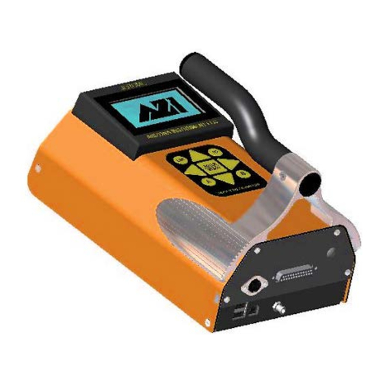
USER MANUAL
®
JEROME
J605
HYDROGEN SULFIDE ANALYZER
June 2013
Firmware v1.2X
ARIZONA INSTRUMENT LLC
3375 N Delaware Street | Chandler, AZ 85225 USA
800.528.7411 | 602.470.1414 | f 602.281.1745
www.azic.com
Email:
General –
azi@azic.com
International –
intl@azic.com
Customer Service –
support@azic.com
AZI P/N 700-0108-E
Last update June 2013
Advertisement
Table of Contents

Related Manuals for Arizona Instrument JEROME J605


Summary of Contents for Arizona Instrument JEROME J605
- Page 1 USER MANUAL ® JEROME J605 HYDROGEN SULFIDE ANALYZER June 2013 Firmware v1.2X ARIZONA INSTRUMENT LLC 3375 N Delaware Street | Chandler, AZ 85225 USA 800.528.7411 | 602.470.1414 | f 602.281.1745 www.azic.com Email: General – azi@azic.com International – intl@azic.com Customer Service –...
- Page 2 J605 Hydrogen Sulfide Analyzer Operation Manual PROPRIETARY RIGHTS NOTICE This manual contains valuable information and material developed by Arizona Instrument LLC ® for use with the Jerome J605 Hydrogen Sulfide Analyzer. No part of this manual can be reproduced or transmitted in any form or by any means, electronic, mechanical or otherwise. This includes photocopying and recording or in connection with any information storage or retrieval system without the express written permission of Arizona Instrument LLC.
-
Page 3: Table Of Contents
Table of Contents UNPACKING THE INSTRUMENT .....................4 INTRODUCTION ...........................6 ® JEROME J605 TECHNICAL SPECIFICATIONS ................8 PRINCIPLE OF OPERATION ......................9 Zero Air Filter (AZI P/N Z2600 3905) .......................11 INSTRUMENT OPERATION .......................12 J605 Main Screen Display ..........................12 J605 Back Panel Connections........................13 J605 User Interface Main Menu Structure ....................14 SAMPLE menu ............................15 REGEN menu .............................17 DATA menu ...............................18... -
Page 4: Unpacking The Instrument
SHIPPED, YOU SHOULD INSURE IT FOR FULL VALUE. • Check for any damage and confirm receipt of all parts on your packing list. Contact Arizona Instrument Customer Service at (800) 528-7411 or (602) 470-1414 if you have any questions. • Press the I/O button. The display will light up and show instrument serial number and software revision. - Page 5 • Perform a sensor regeneration by following these steps: Connect the AC power supply/charger between the matching (DIN) connector on the back of the J605 and an AC power outlet or connect the external battery pack to the back of the J605.
-
Page 6: Introduction
INTRODUCTION ® The Jerome J605 Hydrogen Sulfide Analyzer is an ambient air analyzer with a range of 3 parts per billion (ppb) to 10 parts per million hydrogen sulfide (ppm H S). Readings of 100 ppb or less are displayed in units of ppb, and readings above 100 ppb (0.100 ppm) are displayed in ppm. Readings of zero are displayed as 0.000 ppm or 0.00 ppb depending on the Range in use. - Page 7 Applications • Regulatory compliance • Ambient air analysis • Odor nuisance monitoring • Control room corrosion monitoring • Waste water treatment facilities • Quality control • Scrubber efficiency testing • Accuracy check for other hydrogen sulfide monitors and control systems •...
-
Page 8: Jerome ® J605 Technical Specifications
® JEROME J605 TECHNICAL SPECIFICATIONS Range* 3 ppb (0.003 ppm) to 10 ppm H S in three graduated ranges Resolution 0.02 ppb (20 ppt) H S (range dependent) Response time – sample mode 12 seconds (manual range selection) 1.0 to 10.0 ppm (Range 2) 18 seconds (manual range selection) 0.10 to 1.0 ppm (Range 1) -
Page 9: Principle Of Operation
PRINCIPLE OF OPERATION The heart of the J605 is the well-proven gold film sensing technology. A thin gold film, in the presence of hydrogen sulfide, undergoes an increase in electrical resistance proportional to the mass of hydrogen sulfide in the sample. When the SAMPLE button is pressed, an internal pump pulls ambient air over the gold film sensor for a precise period of time. - Page 10 When sampling in Range 0, (where low levels of hydrogen sulfide are expected) undiluted air samples are drawn across the gold film sensor. Initial Pump, Range 0 Sample Period, Range 0 The instrument’s microprocessor automatically re-zeroes the digital meter at the start of each sample cycle and holds the meter reading until the next sample cycle is activated.
-
Page 11: Zero Air Filter (Azi P/N Z2600 3905)
Zero Air Filter (AZI P/N Z2600 3905) The Zero Air Filter (AZI P/N Z2600 3905) removes hydrogen sulfide, mercury vapor and mercaptans from the air sample. Readings with the filter installed should be near 0.000 ppm (or 0.00 ppb). For maximum accuracy, wait 15 seconds between samples to allow the sensor to restabilize. -
Page 12: Instrument Operation
INSTRUMENT OPERATION J605 Main Screen Display The J605 Main Screen is depicted below, followed by explanations of the labeled items. SYSTEM TIME – As set in the SYSTEM menu. (See SYSTEM menu on page 20) BATTERY – Indicates current charge level and charging status (See Charging Internal Battery on page 28) SOUND ICON –... -
Page 13: J605 Back Panel Connections
J605 Back Panel Connections The above-labeled connections are available from the back panel of the J605. If the USB option has not been activated, the USB ports will not be present. Contact your AZI Sales Representative for information on the USB option. POWER CONNECTOR –... -
Page 14: J605 User Interface Main Menu Structure
J605 User Interface Main Menu Structure NOTE: The main menu also contains a selection labeled “Factory.” This option is for AZI factory use only and is not accessible by the end user. AZI Customer Service 800-528-7411 or 602-470-1414 Page 14 of 57... -
Page 15: Sample Menu
A USB keyboard (AZI P/N: 990-0230) can be used to navigate the menu system and for data entry for items such as Location Names. Connect the USB keyboard to one of the two USB Type “A” ports on the back of the instrument. Either upper or lower case characters may be entered when using a USB keyboard, while only upper case letters are available from the J605 keypad. - Page 16 in samples being taken on the hour, 10 minutes after the hour, 20 minutes after the hour, etc., not every ten minutes from when auto-sampling is initiated. Refer to the chart below for examples of how these intervals work. The Main Screen must be displayed for autosampling takes place, and autosampling will start when the clock reads :00 seconds.
-
Page 17: Regen Menu
SURVEY MODE Highlight SURVEY MODE in the SAMPLE menu and press ENTER/START to begin immediate sampling in survey mode. In survey mode, after an initial four-second pause to purge the flow system, the J605 will sample continuously. For complete information on survey mode, see Survey Mode on page 25. -
Page 18: Data Menu
SET INTERVAL If auto-sampling is being used (as set in SAMPLE MODE above), the J605 can be configured to automatically perform sensor regenerations at a predetermined interval. Use the ▲and ▼arrows to scroll through the available intervals of 6, 12, 24, and 48 hours, and press ENTER/START to save the selected interval. - Page 19 On instruments that have the USB Communications option, all of the data is accessible from the VIEW STORED DATA menu selection. On instruments that do not have the USB Communications option, only the previous two samples are stored. SAVE TO USB DRIVE Before selecting SAVE TO USB DRIVE, connect the target USB memory drive to either USB TYPE “A”...
-
Page 20: System Menu
SYSTEM menu The SYSTEM menu is password protected to prevent unwanted or accidental changes to operating parameters. The default initial password is AZI, but should be changed to something unique if restricted access to the SYSTEM menu is desired. The password can be up to 10 characters long. - Page 21 VIEW SENSOR STATS Use VIEW SENSOR STATS to display the current saturation level of the sensor, the number of regenerations performed on the sensor, and the total number of samples read by the sensor. Press any key to exit the screen when finished. SET SYSTEM TIME The J605 maintains the system time using a 24-hr clock format.
-
Page 22: Daily Operations
Daily Operations ® Before each day's use of the Jerome J605, perform the following steps to verify proper instrument operation: • Press the power I/O button to turn the instrument on. The display will light up and show instrument serial number and software revision. ... -
Page 23: Sensor Regeneration
Sensor Regeneration Sensor regeneration is needed to clean the J605 sensor of any accumulated hydrogen sulfide and to prolong the life of the sensor. This simple procedure should be done: • At the beginning of the day on which the instrument is to be used. •... -
Page 24: Sample Mode
Sample Mode ® This mode, used for standard operation, produces optimum accuracy with the Jerome J605. See ® JEROME J605 TECHNICAL SPECIFICATIONS on page 8 for the accuracy specifications. • Press the power I/O button. The display will light up and briefly show the instrument serial number and software revision. -
Page 25: Survey Mode
Survey Mode Survey Mode takes samples continuously. The result is displayed every 12 to 52 seconds, depending on the H S concentration present. Use this mode to locate hydrogen sulfide spills, leaks, or hot spots, or to assess areas of potentially high hydrogen sulfide concentrations. Sampling in the survey mode is not as accurate. -
Page 26: Operating On Ac Power Or Generator
Operating on AC Power or Generator • For stationary use, the J605 may be operated on AC power. Operating the instrument on AC power at all times eliminates the need for the battery pack and its necessary maintenance. The battery may be disconnected internally or removed completely whenever the instrument is operating on AC power. -
Page 27: External Battery Power
Medium Frequency user: Once per month usage. For this type of user, the instrument should be plugged in for a minimum of three (3) hours prior to use. Otherwise, the instrument can be left unplugged. Infrequent user: Greater than one month between uses or long term storage. For this type of user, the instrument should be fully charged and the battery should be disconnected. -
Page 28: Charging Internal Battery
When operating using the external battery pack, the J605 will shut down after twenty (20) minutes of non-usage. However, if the instrument is running in Survey Mode or Auto-Sampling mode, the instrument will not shut off after twenty minutes. If the J605 is reading low levels of hydrogen sulfide in Survey or Auto-Sampling mode, it will continue to sample until the battery runs out. -
Page 29: Retrieving Data
Retrieving Data On instruments that have the USB Communications option, in addition to viewing the sample data on the instrument, sample data can be transmitted from the J605 for analysis using the USB connections on the back panel of the J605. Data may be transmitted directly to a PC, saved to a USB drive plugged into the J605 or printed to an AZI printer connected to the J605. -
Page 30: Instrument I/O Interface
Instrument I/O Interface The J605 I/O port is a DB-25F connector on the back of the instrument that provides numerous specialized functions for specific industrial applications and for factory use. System integration utilizing the 4-20mA output feature is the most common use of the I/O port. NOTE: This is NOT a printer connection. - Page 31 To utilize the 4-20mA output, connect the positive wire of your 4-20mA system to pin 19 of the I/O port on the J605, and the negative wire to pin 20. The number of each pin of the I/O port is labeled on the port itself, and the locations of pins 19 and 20 can also be seen in the diagram below.
-
Page 32: Maintenance
MAINTENANCE Preventive Maintenance Calendar ® To keep the Jerome J605 operating at peak performance, follow the maintenance schedule below as a guide. Since maintenance is more a function of application and amount of use rather than time, your requirements may be different from the listed schedule. Call AZI Customer Service at 800-528-7411, 602-470-1414, or e-mail support@azic.com for additional guidance for your environment and operation. -
Page 33: Flow System
Flow System ® The Jerome J605's flow system is the crucial link between the sensor and the sample. For the instrument to perform correctly, the flow system must be properly maintained. The user ® maintainable components of this system are the intake filter (.25 inch fritware), the Acrodisc filter, three scrubber filters and connecting tubing. -
Page 34: Internal Filters
Internal Filters Replace the internal filters after six (6) months of use, or as needed. • Press the I/O button to turn the power OFF and unplug the power cord. • Remove the two (2) side screws from the intake end of the instrument and open the case. •... -
Page 35: Replacing The Battery Pack
Replacing the Battery Pack • Press the I/O button to turn the power OFF. • Unplug the power cord. • Use a Phillips screwdriver to remove the four (4) screws securing the battery panel as shown above. • After removing the screws, carefully set the panel to the side. Note that it is still connected to the instrument via the power connector. -
Page 36: Calibration
We strongly recommend you take advantage of our calibration and maintenance service at Arizona Instrument. Service includes filter replacement, component testing, and instrument calibration to NIST traceable standards. A certificate of calibration is issued from AZI when your instrument is factory calibrated. -
Page 37: J605 Troubleshooting
J605 TROUBLESHOOTING Symptom Possible Cause Solution Power Problems Instrument does not turn ON. Discharged battery or Recharge battery for a minimum of 3 hours. Refer to page 28. Battery will not hold a charge. Dead battery. Replace battery. Refer to page 35. Instrument does not turn on when Open fuse. - Page 38 Symptom Possible Cause Solution Low response or erratic readings May need a second regeneration 1. Wait 30 minutes and perform after a long period of non-use. cycle. another sensor regeneration. 2. Test with FTM. Refer to page 3. If still unresponsive, call AZI Customer Service at 800-528- 7411 or 602-470-1414 for assistance.
-
Page 39: Potential Interferences
• NO • Most mercaptans (organic sulfur compounds or “thiols”) Special filters designed to remove chlorine or ammonia gas are available from Arizona Instrument and may be ordered as Chlorine Filter, AZI P/N Z2600-3940 or Ammonia Filter, AZI P/N 990- 0183. -
Page 40: Accessories & Maintenance Parts
ACCESSORIES & MAINTENANCE PARTS PART # ITEM DESCRIPTION Y605-0901 J605 Accessory Kit, Communications Package Instruments (See pictures beginning on page 42) 1400 2002 Probe 1400 3010 Tubing Adapter, 1/4” to 1/8” 2600 3039 Filter, Fritware, 0.25” (1 pack of 20 fritware filters) Z2600 3905 Filter, Zero Air Filter 200-0165 USB Cable, Type A to Type B, 6 ft. - Page 41 Y605-0903 J605 Maintenance Kit (See pictures beginning on page 42) ® 345-0050 1' of 1/8" Tygon tubing ® 2500 3002 2.25' of 1/16" Tygon tubing 2600 3039 Filter, Fritware, 0.25” (1 pack of 20 fritware filters) Z2600 3905 Filter, Zero Air Filter 600-0279 Filter, LFS Scrubber Filter Z2600 3930 Filter, Scrubber Filter 600-0281 Filter, LFD Scrubber Filter...
-
Page 42: Spare Parts & Accessories
Spare Parts & Accessories 4000-1025 AC Power Supply/Charger 200-0143 Battery Pack Assembly 200-0170 Car Accessory Cable 990-0225 10-to-1 Dilution Module AZI Customer Service 800-528-7411 or 602-470-1414 Page 42 of 57... - Page 43 990-0214 External Battery Pack ® 2600 3061 Filter, Acrodisc Filter 990-0183 Filter, Ammonia Filter Z2600 3940 Filter, Chlorine Filter Filter, Fritware, .25 inch 2600 3039 (pack of 20) 600-0281 Filter, LFD Scrubber Filter 600-0279 Filter, LFS Scrubber Filter Z2600 3930 Filter, Scrubber filter Z2600 3905 Filter, Zero Air Filter...
- Page 44 6000 4003 Line Cord (100-120 VAC) (200-0003) (220 VAC Line Cord – UK) (200-0008) (220 VAC Line Cord – Europe) 1400 2002 Probe 1300 0031 Reducer, 1/8” x 3/16” 1400 3010 Tubing adapter ® 345-0050 Tygon tubing 1/8" I.D. (1 foot) ®...
-
Page 45: Appendix A - Usb/Hyperterminal Setup
APPENDIX A – USB/HYPERTERMINAL SETUP Installing the J605 USB Driver ® ® Note: The AZI USB Driver is compatible with Windows XP (32-bit), Windows Vista (64-bit) ® and Windows 7 (32 and 64-bit). However, the HyperTerminal program is only included in ®... - Page 46 ® 3) Windows may display one or more messages indicating that the driver has not passed ® Windows Logo Testing. This driver being installed is a generic Communications Port ® driver that is part of Windows (usbser.sys), so it is safe to ignore this warning. Click “Continue Anyway”...
- Page 47 5) Power on the J605 and connect it to the target computer using the included USB cable ® (AZI P/N: 200-0165). Windows will detect the J605 and its Communications Port and automatically start the New Hardware wizard. The following pictures and descriptions ®...
- Page 48 7) Select “Install the software automatically”, and click Next. ® ® 8) Windows may display a message indicating that the driver has not passed Windows Logo Testing. This driver being installed is a generic Communications Port driver that is ® part of Windows (usbser.sys), so it is safe to ignore this warning.
- Page 49 ® 9) Windows will copy a file and finish the wizard. Click Finish. ® 10) Windows will then indicate that the driver has been successfully installed. AZI Customer Service 800-528-7411 or 602-470-1414 Page 49 of 57...
- Page 50 Using HyperTerminal to receive data from the J605 1) The J605 should be connected to the PC’s USB port and powered on before HyperTerminal is launched or HyperTerminal may not see the COM port in use. 2) Start HyperTerminal (Start All Programs Accessories Communications HyperTerminal).
- Page 51 5) Next, a window labeled Connect To will be displayed. Find the last dropdown list in the dialog box labeled Connect using:. Select the last COM port from the list and click OK. 6) Next, HyperTerminal will prompt for Port Settings. These settings do not apply to USB ports, so the default values do not need to be changed.
- Page 52 7) A blank HyperTerminal screen will be displayed. On the status bar in the lower left hand corner it should say Connected. 8) Select Capture Text... from the Transfer menu on the main HyperTerminal window. AZI Customer Service 800-528-7411 or 602-470-1414 Page 52 of 57...
- Page 53 9) HyperTerminal will prompt for a file to save the data to. It is recommended that the data be saved to either the Desktop or My Documents. 10) Go to the J605 and navigate to the DATA menu, then highlight Send to PC and press ENTER/START.
- Page 54 12) When the J605 stops sending data, Click HyperTerminal's Transfer menu again and click Capture Text, then Stop 13) If you did not receive any text from the J605: a) Go to the Call menu, click Disconnect b) Go to the File menu, click Properties c) You will see the same window as in step 4) above.
-
Page 55: Appendix B - J605 Functional Test Module
APPENDIX B - J605 FUNCTIONAL TEST MODULE ® The Jerome Hydrogen Sulfide Functional Test Module (AZI P/N: Z2600 0918 or Z2600 0930) ® provides a fast and easy method of verifying that Jerome J605 Hydrogen Sulfide Analyzers are functioning correctly. The Functional Test Module is beneficial: ... -
Page 56: Warranty
WARRANTY ® Arizona Instrument LLC (seller) warrants to buyer that Jerome products delivered pursuant to this agreement shall, at the time of delivery, and for a period of one (1) year thereafter (the Internal Battery Pack, where applicable, is warranted for a period of ninety [90] days only), to be free from defects in material or workmanship and shall conform to seller's specifications or such other specifications as seller has agreed to in writing. - Page 57 AZI logo are all registered trademarks of Arizona Instrument LLC. Instrument firmware is copyright protected. All specifications subject to change without notice. © Copyright 2010-2013 Arizona Instrument LLC. All Rights Reserved. ® Resisorb is a registered trademark of Avantor Performance Materials.
Need help?
Do you have a question about the JEROME J605 and is the answer not in the manual?
Questions and answers