Table of Contents
Advertisement
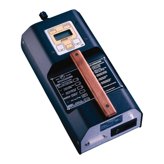
USER MANUAL
®
JEROME
431-X
MERCURY VAPOR ANALYZER
OPERATION MANUAL
September 2017
ARIZONA INSTRUMENT LLC
3375 N Delaware Street | Chandler, AZ 85225 USA
800.528.7411 | 602.470.1414 | f 602.281.1745
www.azic.com
Email:
General –
azi@azic.com
International –
intl@azic.com
Customer Service –
support@azic.com
AZI P/N 700-0046-F
Last update September 2017
Advertisement
Table of Contents
Troubleshooting

Related Manuals for Arizona Instrument JEROME 431-X


Summary of Contents for Arizona Instrument JEROME 431-X
- Page 1 USER MANUAL ® JEROME 431-X MERCURY VAPOR ANALYZER OPERATION MANUAL September 2017 ARIZONA INSTRUMENT LLC 3375 N Delaware Street | Chandler, AZ 85225 USA 800.528.7411 | 602.470.1414 | f 602.281.1745 www.azic.com Email: General – azi@azic.com International – intl@azic.com Customer Service –...
- Page 2 431-X Mercury Vapor Analyzer Operation Manual PROPRIETARY RIGHTS NOTICE This manual contains valuable information and material developed by Arizona Instrument LLC ® for use with the Jerome 431-X Mercury Vapor Analyzer. No part of this manual can be reproduced or transmitted in any form or by any means, electronic, mechanical or otherwise.
-
Page 3: Table Of Contents
Table of Contents FOR THOSE WHO CAN'T READ THE WHOLE MANUAL NOW ..........5 INTRODUCTION ...........................7 PRINCIPLE OF OPERATION ......................8 Zero Air Filter ............................9 INSTRUMENT OPERATION .......................10 LCD Codes ..............................10 Daily Operations ............................11 Sensor Regeneration ...........................12 Zero Adjust ..............................13 Sample Mode ..............................14 Survey Mode ..............................15 Operating on AC Power or Generator ......................16 Operating on Internal Battery Power ......................16... - Page 4 Auto-Sample ...............................48 4-20 mA Analog Output ..........................49 Connection and Setup:.........................50 Fresh Air Solenoid ............................52 DC Power Operation ..........................53 DC Power Adaptor Kit, AZI P/N Y031 0902 ..................53 15. WARRANTY ............................55 An up-to-date electronic copy of this manual can be found at: http://www.azic.com/downloads.aspx AZI Customer Service 800-528-7411 or 602-470-1414 Page 4 of 56...
-
Page 5: For Those Who Can't Read The Whole Manual Now
SHIPPED, YOU SHOULD INSURE IT FOR FULL VALUE. • Check for any damage and confirm receipt of all parts on your packing list. Contact Arizona Instrument Customer Service at (800) 528-7411 or (602) 470-1414 if you have any questions. • Press the ON button. The display should read 000 in less than one second. - Page 6 • Perform a sensor regeneration by following these steps: Connect the line cord between the connector on the back of the 431-X and an AC power outlet. Press the ON switch and then press the REGEN button. The instrument will begin a 10 minute regeneration cycle, indicated by .H.H.H flashing on the display.
-
Page 7: Introduction
INTRODUCTION ® The Jerome 431-X Mercury Vapor Analyzer is an ambient air analyzer with a range of 0.001 to .999 milligrams of mercury vapor per cubic meter (mg/m Hg). CAUTION: ® The Jerome 431-X is for vapor use only. DO NOT allow the probe or the instrument's intake to be exposed to any liquid, dust or other foreign material. -
Page 8: Principle Of Operation
Applications • Ambient air analysis • Regulatory compliance • Quality assurance and quality control • Scrubber efficiency testing • Accuracy check for other Mercury Vapor monitors and control systems • Mercury Vapor source detection • Leak detection • Portable Mercury Vapor detection ®... -
Page 9: Zero Air Filter
The sample air passes through a filter (removing any acidic gases which interfere with the sensor's response to mercury) and is drawn over the gold film sensor. The sensor absorbs the Mercury Vapor. Nine seconds after starting, the sample solenoid bypass closes and the remainder of the sample is drawn through the scrubber filter and the flow system. -
Page 10: Instrument Operation
INSTRUMENT OPERATION LCD Codes LCD CODE EXPLANATION Ready to sample .000 No Mercury Vapor reading 00.0 No Mercury Vapor reading, display in nanograms .8.8.8 Sensor saturated-regeneration needed (refer to page 12) .H.H.H Sensor regeneration in progress (.H.H.H flashes) .L.L.L Re-zero needed (refer to page 13) .P.P.P Power cord required or low line power, <100 VAC (or 200 VAC) (see pages 16 and 17, Changing the Fuse, if .P.P.P remains on after... -
Page 11: Daily Operations
Daily Operations ® Before each day's use of the Jerome 431-X, perform the following steps to verify proper instrument operation: • Press the power ON button. The digital meter displays 000. (Disregard the digital meter's initial momentary reading.) ... -
Page 12: Sensor Regeneration
Sensor Regeneration Sensor regeneration is needed to clear the 431-X sensor of any accumulated Mercury Vapor and to prolong the life of the sensor. This simple procedure should be done: • At the beginning of the day on which the instrument is to be used. •... -
Page 13: Zero Adjust
Zero Adjust • To ensure air entering the instrument is clean, install the zero air filter in the instrument’s intake and sample until the readings stabilize. • While pressing the ZERO button, turn the ZERO ADJUST potentiometer (shown at right) using the trimmer tool until the digital meter reads 0. -
Page 14: Sample Mode
Sample Mode This mode, used for standard operation, produces optimum accuracy (±5% at 0.100 mg/m ® with the Jerome 431-X. • Press the power ON button. The digital meter displays 000. If the unit is set to display in ng, the digital meter displays 00.0. -
Page 15: Survey Mode
Survey Mode The survey mode takes samples every 3 seconds automatically. Use this mode to locate mercury spills or to assess areas of potentially high mercury concentrations. Sampling in the survey mode is not as accurate. Due to the decreased sample volume, the accuracy of the instrument is reduced to ±... -
Page 16: Operating On Ac Power Or Generator
Operating on AC Power or Generator • For stationary use, the 431-X may be operated on AC power. Operating the instrument on AC power at all times eliminates the need for the battery pack and its necessary maintenance. The battery may be unplugged or removed completely whenever the instrument is operating on AC power. -
Page 17: Charging Batteries
Charging Batteries • Press the power OFF button. • Connect the AC power cord between the 431-X power receptacle and an AC power source. Complete battery recharging takes 14 hours. The 431-X contains a trickle charger so it may be continually plugged into an AC power source without damaging the battery pack. -
Page 18: Maintenance
MAINTENANCE Preventive Maintenance Calendar ® To keep the Jerome 431-X operating at peak performance, follow the maintenance schedule below as a guide. Since maintenance is more a function of application and amount of use rather than time, your requirements may be different from the listed schedule. Call AZI Customer Service at 800-528-7411, 602-470-1414, or e-mail support@azic.com for additional guidance for your environment and operation. -
Page 19: Flow System
Flow System ® The Jerome 431-X's flow system is the crucial link between the sensor and the sample. For the instrument to perform correctly, the flow system must be properly maintained. The user maintainable components of this system are the intake filter (.25 inch fritware), a C/M Filter, two scrubber filters and connecting tubing. -
Page 20: Internal Filters
Internal Filters • Replace the internal filters after six (6) months of use, or as needed. • Press the power OFF button and unplug the power cord. • Remove the two (2) side screws from the intake end of the instrument and open the case. •... -
Page 21: Replacing The Battery Pack
Replacing the Battery Pack • Press the power OFF button. • Unplug the power cord. • Remove the two (2) side screws from the intake end of the instrument and open the case lid. • Disconnect the battery connector from the board. •... -
Page 22: Display Nanograms Or Milligrams Per Cubic Meter
• Remove the two screws toward the front of the instrument and open the lid. • Locate the DIP Switch SW2 at the top of the main circuit board. o Non-SMV units: SW2 is the red DIP switch illustrated at top right. -
Page 23: Calibration
We strongly recommend you take advantage of our calibration and maintenance service at Arizona Instrument. Call Customer Service at (800) 528-7411 or (602) 470-1414 to arrange re- calibration. A certificate of calibration is issued from AZI when your instrument is factory calibrated. -
Page 24: 431-X Troubleshooting
431-X TROUBLESHOOTING Symptom Possible Cause Solution Power Problems Unit does not turn ON. Unit Discharged battery or Recharge battery for a minimum of turns on when power cord is 14 hours. Refer to page 17. plugged in. LCD displays 000 Dead battery. - Page 25 Sampling Problems Airflow is restricted during the Kinks and crimps in the Periodically check the Tygon tubing sensor regeneration cycle, causing Tygon tubing. inside the instrument. Refer to possible permanent damage. page 20. 1. Install zero air filter in intake High erratic results.
- Page 26 False readings, may go to .8.8.8 or Extremely cold or extremely If sampling under these conditions, .L.L.L. warm air sampled into unit. install zero air filter in intake. Sample until display reads 0.003 mg/m3 or less. This equilibrates sensor temperature with the temperature of the sample air stream.
-
Page 27: Jerome ® 431-X Technical Specifications
® JEROME 431-X TECHNICAL SPECIFICATIONS Range 0.001 to 0.999 mg/m Detection Limit 0.003 mg/m Precision 5% relative standard deviation at 0.100 mg/m Accuracy ±5% at 0.100 mg/m Response time-sample mode 12 seconds Response time-survey mode 3 seconds Flow rate 750 ± 50ml/min (0.75 ± .05 liters/min) 100-120 VAC, 50/60 Hz, 1 A, or Power requirements 220-240 VAC, 50/60 Hz, 1 A... -
Page 28: Instrument I/O Interface
Instrument I/O Interface The 431-X I/O port (25 pin D-sub) provides the following functions: • Serial data communication Interface type: RS-232C full duplex, DCE Parameters: 1200 Baud, 1 start bit, 8 data bits, 2 stop bits, no parity ... -
Page 29: Potential Interferences
In addition, a special filter designed to remove chlorine gas from the sample stream is available from Arizona Instrument and may be ordered as Chlorine Filter, AZI P/N Z2600-3940. -
Page 30: Accessories & Maintenance Parts
ACCESSORIES & MAINTENANCE PARTS PART # ITEM DESCRIPTION Y431 0901 431 Accessory Kit (See pictures beginning on page 32) 1400 2002 Probe 1400 3010 Tubing Adapter, 1/4” to 1/8” 2300 0001 Trimmer Tool 2600 3039 .25 Fritware 6000 4003 Line Cord, 115 VAC - USA and Canada Alt. - Page 31 ® Jerome Data Logger & JCS. ® Includes the external Jerome ® Data Logger and Jerome Y990-0259 Communication Software (JCS) Kit (see below) * For Non-SMV instruments ® Jerome Communication Software Kit (JCS) Y990-0257 (external Data Logger not included) * For SMV instruments Y990-0258 For customers with prior version (software...
-
Page 32: Spare Parts
Spare Parts Stopper A2600 0902 Assembly Z2600 3914 Septum Holder 3200 0011 Septa Syringe A2600 0903 Assembly Syringe Needles, 2600 0022 22 Ga. 1400 2002 Probe 2300 0001 Trimmer 1/8 x 3/16 1300 0031 reducer Battery Pack Z4000 0907 Assembly (115V) Battery Pack Z4000 0908... - Page 33 Z2600 3905 Zero air filter Z2600 3928 C/M filter Z2600 3930 Scrubber filter Z2600 3940 Chlorine Filter 990-0193 Ammonia Filter 1400 3010 Tubing adapter Includes mounting hardware Y2600 3945 Intake Kit PS-151 Tube Nut 2600 3039 .25 inch fritware Tygon tubing 2500 3001 1/8"...
- Page 34 115 VAC IDC battery charger 4000 1011 (Used to charge an uninstalled battery) 230 VAC IDC battery charger 4000 1012 (Used to charge an uninstalled battery) 100-120 VAC 6000 4003 Line Cord 220-240 VAC Alternate – Line Cord for 200-0003 England AZI Customer Service 800-528-7411 or 602-470-1414 Page 34 of 56...
- Page 35 220-240 VAC Alternate – Line Cord for 200-0008 Europe 10 to 1 Dilution 990-0223 Module 5100 1012 Spare Fuse ® 6000 1055 Jerome Communication Cable For current prices and delivery information, call AZI Customer Service at (800) 528-7411 or (602) 470-1414. AZI Customer Service 800-528-7411 or 602-470-1414 Page 35 of 56...
-
Page 36: Factory Calibration Service
Factory Calibration Service Service includes filter replacement, component testing, and instrument calibration to NIST traceable standards. For scheduling and shipping authorization, call AZI Customer Service at (800) 528-7411 or (602) 470-1414. AZI Customer Service 800-528-7411 or 602-470-1414 Page 36 of 56... -
Page 37: Appendix A - 431-X Functional Test Kit
APPENDIX A - 431-X FUNCTIONAL TEST KIT If your application requires frequent verification of instrument functionality, this test will benefit you. If the test results fall within the expected range, you may assume the instrument is functioning properly. THIS IS A FIELD CHECK OF THE FUNCTIONALITY OF THE INSTRUMENT. THIS TEST DOES NOT CALIBRATE THE INSTRUMENT. -
Page 38: Mercury Transfer
Mercury Transfer • CAREFULLY pour the mercury into the center of the FTK mercury vessel’s opening. ENSURE that no mercury residue is on the outside of the vessel. See the supplier’s Safety Data Sheets (SDS) or call AZI Customer Service at 1-800-528-7411 or 1-602- 470-1414 for clean-up instructions. -
Page 39: Functional Test Procedure
Functional Test Procedure NOTE: Perform the functional test ONLY after sensor regeneration. • Allow the FTK mercury vessel to remain stable at room temperature for at least 2 hours. The temperature range for the test is 16 - 24 ºC. ... -
Page 40: Syringe Technique
Syringe Technique • Pull and hold the syringe plunger against the bar-stop. • Verify that the black mark on the syringe plunger aligns with the 1cc mark on the syringe barrel. If it does not, the holder assembly must be adjusted. Call AZI customer service at 602-281- 1745 or 800-528-7411 for assistance. -
Page 41: 431-X Temperature Conversion Chart
• When the display flashes, release the plunger and allow gravity to feed the mercury vapor into the airstream. If the plunger stops, gently press it completely closed. • Remove the syringe needle from the septum. 431-X Temperature Conversion Chart Temperature in °C Digital Meter Response .091 to .123... -
Page 42: Functional Test Troubleshooting
Functional Test Troubleshooting If you don’t achieve good results with the functional test procedure, check the following: Results Solution Typically too high Ensure the FTK mercury vessel temperature is stable. Be sure to inject the Hg vapor ONLY after the display flashes (approximately 2 seconds after SAMPLE is pressed). -
Page 43: Appendix B - Internal Dip Switch Settings
APPENDIX B - INTERNAL DIP SWITCH SETTINGS Main circuit board DIP switch SW2: Locate the DIP Switch SW2 at the top of the main circuit board. • Non-SMV units: SW2 is the red DIP switch illustrated at top right. • SMV units: SW2 is the black DIP switch illustrated below right. -
Page 44: Appendix C - Jerome Communications Software
® APPENDIX C - JEROME COMMUNICATIONS SOFTWARE ® The Jerome Communications Software (JCS) is used with 431-X Mercury Vapor Analyzers that feature the communications configuration option, available in both SMV and Non-SMV instruments. • The JCS allows the user to program the instrument for unattended monitoring and to ®... -
Page 45: Jcs Kit Contents
JCS Kit Contents • Jerome ® Communication Software on CD-ROM with security key • Jerome ® Communication Cable • User’s manual For full details on JCS refer to the JCS Manual AZI# 700-0138 or contact your sales representative. Optional equipment for Non-SMV instruments: •... -
Page 46: Appendix D - Jerome
® APPENDIX D - JEROME 431-X OPTION FUNCTIONALITY On Non-SMV instruments, the Option Functionality is provided by the Option Circuit Board mounted on the Main Circuit Board. On SMV instruments equipped with the Option Functionality, the Option Functionality is integrated into the Main Circuit Board. Proper use of the Option Functionality requires that the base instrument be fully functional and set correctly for the intended operation. -
Page 47: Instrument Zeroing
Instrument Zeroing ® The Jerome 431-X has three ways to zero the sensor reading before samples are taken if the Option Functionality is installed: (1) The instrument automatically re-zeroes between samples so that each sample is a unique reading. To take a sample, simply press the SAMPLE button. (2) The manually adjusted zero, using the switch on the top of the 431-X, is used to re-establish a baseline between the reference and sensor gold films only after a sensor regeneration. -
Page 48: Timed Regeneration
Timed Regeneration If the unit is to be operated unattended for extended periods, AZI recommends that the sensor be regenerated regularly. Operation under JCS or Data Logger control automatically regenerates saturated sensors. The Option Functionality can control regeneration on a regular basis, every 6, 12 or 24 hours. -
Page 49: 4-20 Ma Analog Output
4-20 mA Analog Output The analog output signal at pin 18 of the 25-pin connector can be configured to provide the instrument's native mode 0-2 Volt output or the optional 4-20 mA output by setting a single jumper. Refer to the tables below for jumper placement. (Pin 23 is the ground pin for the analog output function. -
Page 50: Connection And Setup
® Jerome 431-X instruments shipped after early 1995 are capable of providing 0-2 volts analog output. Instruments shipped before that time can be upgraded by a firmware update and adjustment. Instruments can be upgraded to have 4-20 mA output with the addition of the Option Functionality upgrade. This must be performed at the factory. - Page 51 • The 4-20 mA passive receivers do not contain a voltage source to power the loop current. They require the addition of a separate isolated power supply. Typically a supply that delivers 15 to 20 volts DC at 50 mA is sufficient. Wire these as in Figure 3. Note that some 12-volt DC wall transformers (as used on portable equipment) may deliver 15 to 20 volts when they are lightly loaded.
-
Page 52: Fresh Air Solenoid
Fresh Air Solenoid An external three-way solenoid can be used to provide fresh air or conditioned air during sensor regeneration. This may be necessary if the sample stream lacks molecular oxygen. A low current six volt DC solenoid, connected between pins 19 and 11 of the 25 pin rear panel connector, will be energized during the regeneration cycle if the Option Functionality switch SW100 #6 is placed in the OFF position. -
Page 53: Dc Power Operation
DC Power Operation Instruments with the 431-X Option Functionality can be used with any +12 VDC source for continuous operation, if the AZI Power Inverter Kit, P/N Y031 0902 is purchased. To preserve the life of the DC power source, usually a car or truck battery, the power inverter will switch on automatically to supply the AC necessary for regeneration only. - Page 54 Ensure that the inverter’s power switch is in the “OFF” position. LEAVE the power switch in the “OFF” position at all times. The interface board will activate the inverter when necessary. If the inverter power switch is placed in the “ON” position, it will cause a continuous drain on the external 12-volt power system.
-
Page 55: Warranty
WARRANTY ® Arizona Instrument LLC (seller) warrants to buyer that Jerome products delivered pursuant to this agreement shall, at the time of delivery, and for a period of one (1) year. Thereafter (the Internal Battery Pack, where applicable, is warranted for a period of ninety [90] days only), to be free from defects in material or workmanship and shall conform to seller's specifications or such other specifications as seller has agreed to in writing. - Page 56 AZI are all registered trademarks of Arizona Instrument LLC. Instrument firmware is copyright protected. All specifications subject to change without notice. © Copyright 1990-2017 Arizona Instrument LLC. All Rights Reserved. ® Resisorb is a registered trademark of Avantor Performance Materials.
Need help?
Do you have a question about the JEROME 431-X and is the answer not in the manual?
Questions and answers