Advertisement
Quick Links
ISTR - 910/ 00
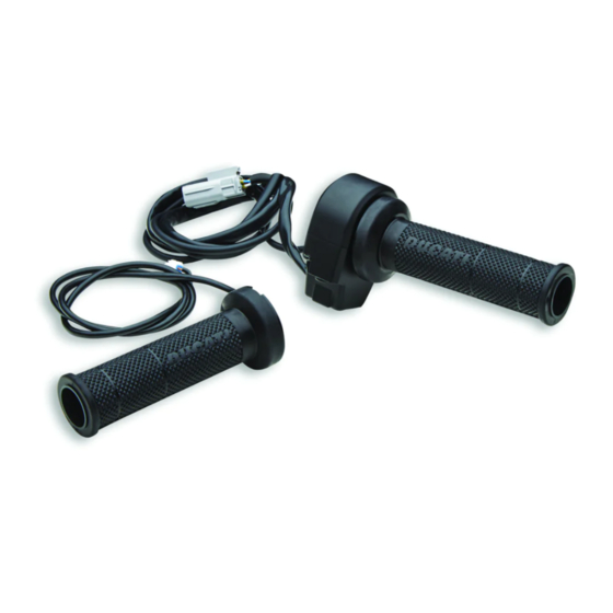
Kit manopole riscaldate - 96680702A
Heated handgrip kit - 96680702A
Simbologia
Per una lettura rapida e razionale sono stati impiegati simboli che
evidenziano situazioni di massima attenzione, consigli pratici o
semplici informazioni. Prestare molta attenzione al significato dei
simboli, in quanto la loro funzione è quella di non dovere ripete-
re concetti tecnici o avvertenze di sicurezza. Sono da considerare,
quindi, dei veri e propri "promemoria". Consultare questa pagina
ogni volta che sorgeranno dubbi sul loro significato.
Attenzione
La non osservanza delle istruzioni riportate può creare una situa-
zione di pericolo e causare gravi lesioni personali e anche la morte.
Importante
Indica la possibilità di arrecare danno al veicolo e/o ai suoi compo-
nenti se le istruzioni riportate non vengono eseguite.
Note
Fornisce utili informazioni sull'operazione in corso.
Riferimenti
I particolari evidenziati in grigio e riferimento numerico (Es.
rappresentano l'accessorio da installare e gli eventuali componenti
di montaggio forniti a kit.
I particolari con riferimento alfabetico (Es.
componenti originali presenti sul motoveicolo.
Tutte le indicazioni destro o sinistro si riferiscono al senso di marcia
del motociclo.
Avvertenze generali
Attenzione
Le operazioni riportate nelle pagine seguenti devono essere ese-
guite da un tecnico specializzato o da un'officina autorizzata Du-
cati.
Attenzione
Le operazioni riportate nelle pagine seguenti se non eseguite a re-
gola d'arte possono pregiudicare la sicurezza del pilota.
Note
Documentazione necessaria per eseguire il montaggio del Kit è il
Manuale Officina, relativo al modello di moto in vostro possesso.
Note
Nel caso fosse necessaria la sostituzione di un componente del kit
consultare la tavola ricambi allegata.
1
Symbols
The symbols used in this manual are aimed at making reading direct
and easy. The symbols are used either to draw the reader's attention on
potentially hazardous conditions, or to give practical advice or to supply
general information. Pay the utmost attention to these symbols as they
are used to remind of technical principles or safety measures which will
not be repeated extensively. They must therefore be considered as "re-
minders". Check with this page in case of doubt about their meaning.
Failure to comply with these instructions may put you at risk and
lead to severe injury or death.
It indicates the possibility of damaging the motorcycle and/or its
components if the instructions are not followed.
It supplies useful information about the operation in progress.
References
1
)
The parts highlighted in grey and with a reference number (e.g.
) represent the accessory to be installed and any assembly compo-
nents supplied with the kit.
A
) rappresentano i
The parts with alphabetic reference (e.g.
components present on the motorcycle.
All left and right indications are referred to the motorcycle direc-
tion of travel (forward riding position).
General notes
The operations listed in the following pages must be carried out by
a specialised technician or by a Ducati authorised service centre.
Carefully perform the operations on the following pages since they
might negatively affect rider safety.
The Workshop Manual of your motorcycle model is the documen-
tation required to assemble the Kit.
Should it be necessary to change any kit parts, please refer to the
attached spare part table.
Operating, servicing and maintaining a passenger vehicle or off-
highway motor vehicle can expose you to chemicals including en-
gine exhaust, carbon monoxide, phthalates, and lead, which are
known to the State of California to cause cancer and birth defects
or other reproductive harm. To minimize exposure, avoid breath-
ing exhaust, do not idle the engine except as necessary, service
your vehicle in a well-ventilated area and wear gloves or wash your
hands frequently when servicing your vehicle. For more informa-
tion go to www.P65Warnings.ca.gov/passenger-vehicle.
Warning
Important
Notes
Warning
Warning
Notes
Notes
Warning
1
A
) represent the original
Advertisement

Related Manuals for DUCATI Performance 96680702A


Summary of Contents for DUCATI Performance 96680702A
- Page 1 ISTR - 910/ 00 Kit manopole riscaldate - 96680702A Heated handgrip kit - 96680702A Simbologia Symbols Per una lettura rapida e razionale sono stati impiegati simboli che The symbols used in this manual are aimed at making reading direct evidenziano situazioni di massima attenzione, consigli pratici o and easy.
- Page 2 ISTR 910 / 00 Importante Important I componenti del kit possono essere soggetti ad aggiornamenti; The parts of the kit can be updated; for information always up to consultare il DCS (Dealer Communication System) per avere infor- date, please refer to DCS (Dealer Communication System). mazioni sempre aggiornate.
- Page 3 ISTR 910 / 00 Smontaggio componenti originali Removing the original components Smontaggio comando acceleratore Throttle control disassembly Operando sul lato destro del motoveicolo, scollegare lo spinotto Working on motorcycle RH side, disconnect the throttle control comando acceleratore (A2) dal connettore cablaggio principale pin (A2) from the main wiring connector (B1).
- Page 4 ISTR 910 / 00 Divincolare la parte esterna del paramani destro (D) dal manubrio Free the outer side of RH hand guard (D) from handlebar (E), pay- (E), prestando attenzione che la boccola ad espansione (D2) resti ing attention to keep the expansion bushing (D2) fixed to the screw fissata alla vite (D1).
- Page 5 ISTR 910 / 00 Smontaggio manopola sinistra LH handgrip disassembly Operando sul lato sinistro del motoveicolo, rimuovere il tappo (C1) Working on motorcycle LH side, remove plug (C1) from connector dal connettore (F). Allentare la vite (G1) di fissaggio paramani sini- (F).
- Page 6 ISTR 910 / 00 Divincolare la parte esterna del paramani sinistro (G) dal manubrio Free the outer side of LH hand guard (G) from handlebar (E), pay- (E), prestando attenzione che la boccola ad espansione (G2) resti ing attention to keep the expansion bushing (G2) fixed to the screw fissata alla vite (G1).
- Page 7 ISTR 910 / 00 1,5 Nm ± 10% 10 Nm ± 10% Montaggio componenti kit Assembling the kit components Importante Important Verificare, prima del montaggio, che tutti i componenti risultino Before assembling, check that all parts are clean and in good con- puliti e in perfetto stato.
- Page 8 ISTR 910 / 00 Sistemare i cablaggi lungo il cruscotto come indicato in figura. Col- Lay the wirings along the instrument panel as shown in the figure. legare lo spinotto comando acceleratore (1C) al connettore (B1). Connect the throttle control pin (1C) to connector (B1). Connect the Collegare lo spinotto riscaldamento comando acceleratore (1D) al throttle control heating pin (1D) to connector (B2).
- Page 9 ISTR 910 / 00 2,8 Nm ± 5% 2,8 Nm ± 5% Montaggio manopola riscaldata sinistra LH heated handgrip assembly Verificare che il cavo (2A) sia correttamente inserito nell’apposita Check that the cable (2A) is correctly inserted in the specific front sede anteriore della manopola riscaldata sinistra (2), come mostra- seat of the LH heated handgrip (2), as shown in the figure.
- Page 10 ISTR 910 / 00 10 Nm ± 10% Sistemare il cablaggio lungo il cruscotto come indicato in figura. Lay the wiring along the instrument panel as shown in the figure. Collegare lo spinotto riscaldamento manopola sinistra (2B) al con- Connect the LH handgrip heating pin (2B) to connector (F). Use the nettore (F).
- Page 11 ISTR - 910/ 00 Kit poignées chauffantes - 96680702A Kit beheizte Lenkergriffe - 96680702A Symboles Symbole Pour une lecture rapide et rationnelle on a utilisé des symboles de Für ein schnelles und zweckmäßiges Lesen dieser Anleitung wur- mise en évidence de situations demandant une attention maxi- den Symbole verwendet, die Situationen, die höchste Aufmerk-...
- Page 12 ISTR 910 / 00 Important Wichtig Les composants du kit peuvent être soumis à des mises à jour ; Die Bestandteile des Kits können Aktualisierungen unterliegen. veuillez consulter le DCS (Dealer Communication System) pour des Lesen Sie stets die Angaben im DCS (Dealer Communication Sys- informations toujours actualisées.
- Page 13 ISTR 910 / 00 Dépose des composants d'origine Abnahme der Original-Bestandteile Dépose commande des gaz Abnahme der Gassteuerung En agissant du côté droit du motocycle, débrancher la broche de An der rechten Seite des Motorrads den Stecker (A2) der Gassteu- la commande des gaz (A2) du connecteur du câblage principal (B1).
- Page 14 ISTR 910 / 00 Dégager la partie extérieure de la protection mains droite (D) du Den Außenteil des rechten Handschutzes (D) vom Lenker (E) ab- guidon (E), en veillant à ce que la bague d'expansion (D2) reste drücken und dabei darauf achten, dass die Spreizbuchse (D2) an fixée à...
- Page 15 ISTR 910 / 00 Dépose poignée gauche Abnahme des linken Lenkergriffs En agissant du côté gauche du motocycle, déposer le bouchon (C1) An der linken Seite des Motorrads die Verschlusskappe (C1) vom du connecteur (F). Desserrer la vis (G1) de fixation protection mains Verbinder (F) entfernen.
- Page 16 ISTR 910 / 00 Dégager la partie extérieure de la protection mains gauche (G) du Den Außenteil des linken Handschutzes (G) vom Lenker (E) abdrü- guidon (E), en veillant à ce que la bague d'expansion (G2) reste cken und dabei darauf achten, dass die Spreizbuchse (G2) an der fixée à...
- Page 17 ISTR 910 / 00 1,5 Nm ± 10% 10 Nm ± 10% Pose des composants kit Montage der Kit-Bestandteile Important Wichtig Avant la pose, vérifier que tous les composants sont propres et en Vor der Montage überprüfen, dass alle Bestandteile sauber sind bon état.
- Page 18 ISTR 910 / 00 Prédisposer les câblages le long du tableau de bord comme la Die Verkabelung der Abbildung gemäß am Cockpit entlang ver- figure le montre. Brancher la broche commande des gaz (1C) au legen. Den Stecker (1C) der Gassteuerung an den Verbinder (B1) connecteur (B1).
- Page 19 ISTR 910 / 00 2,8 Nm ± 5% 2,8 Nm ± 5% Pose poignée chauffante gauche Montage des linken beheizten Lenkergriffs Vérifier que le câble (2A) est correctement introduit dans le loge- Überprüfen, dass das Kabel (2A) korrekt in den entsprechenden ment avant spécifique de la poignée chauffante gauche (2), comme vorderen Sitz des linken beheizten Lenkergriffs (2), wie auf der Ab- la figure le montre.
- Page 20 ISTR 910 / 00 10 Nm ± 10% Prédisposer le câblage le long du tableau de bord comme la fi- Die Verkabelung der Abbildung gemäß am Cockpit entlang verle- gure le montre. Brancher la broche chauffage poignée gauche (2B) gen. Den Stecker der Heizung des linken Lenkergriffs (2B) an den au connecteur (F).
-
Page 21: Advertências Gerais
ISTR - 910/ 00 Conjunto punhos aquecidos - 96680702A Heated handgrip kit - 96680702A Símbolos Symbols Para uma leitura rápida e racional foram empregues símbolos que The symbols used in this manual are aimed at making reading direct evidenciam situações de máxima atenção, conselhos práticos ou and easy. - Page 22 ISTR 910 / 00 Importante Important Os componentes do conjunto podem sofrer atualizações; consulte The parts of the kit can be updated; for information always up to o DCS (Dealer Communication System) a fim de obter informações date, please refer to DCS (Dealer Communication System). sempre atualizadas.
- Page 23 ISTR 910 / 00 Desmontagem dos componentes originais Removing the original components Desmontagem do comando do acelerador Throttle control disassembly Atuando no lado direito da moto, desligue o cavilhão de comando Working on motorcycle RH side, disconnect the throttle control do acelerador (A2) do conector da cablagem principal (B1).
- Page 24 ISTR 910 / 00 Liberte a parte externa do protetor de mãos direito (D) do guia- Free the outer side of RH hand guard (D) from handlebar (E), pay- dor (E), prestando atenção para que o casquilho de expansão (D2) ing attention to keep the expansion bushing (D2) fixed to the screw fique fixado no parafuso (D1).
- Page 25 ISTR 910 / 00 Desmontagem do punho esquerdo LH handgrip disassembly Atuando no lado esquerdo da moto, remova a tampa (C1) do co- Working on motorcycle LH side, remove plug (C1) from connector nector (F). Alivie o parafuso (G1) de fixação do protetor de mãos (F).
- Page 26 ISTR 910 / 00 Liberte a parte externa do protetor de mãos esquerdo (G) do guia- Free the outer side of LH hand guard (G) from handlebar (E), pay- dor (E), prestando atenção para que o casquilho de expansão (G2) ing attention to keep the expansion bushing (G2) fixed to the screw fique fixado no parafuso (G1).
- Page 27 ISTR 910 / 00 1,5 Nm ± 10% 10 Nm ± 10% Montagem dos componentes do conjunto Assembling the kit components Importante Important Verifique, antes da montagem, se todos os componentes estão Before assembling, check that all parts are clean and in good con- limpos e em perfeito estado.
- Page 28 ISTR 910 / 00 Organize as cablagens ao longo do painel de instrumentos, con- Lay the wirings along the instrument panel as shown in the figure. forme indicado na figura. Ligue o pino do comando do acelerador Connect the throttle control pin (1C) to connector (B1). Connect the (1C) ao conector (B1).
- Page 29 ISTR 910 / 00 2,8 Nm ± 5% 2,8 Nm ± 5% Montagem do punho aquecido esquerdo LH heated handgrip assembly Verifique que o cabo (2A) esteja corretamente inserido na específi- Check that the cable (2A) is correctly inserted in the specific front ca sede dianteira do punho aquecido esquerdo (2), como mostrado seat of the LH heated handgrip (2), as shown in the figure.
- Page 30 ISTR 910 / 00 10 Nm ± 10% Organize a cablagem ao longo do painel de instrumentos, confor- Lay the wiring along the instrument panel as shown in the figure. me indicado na figura. Ligue o pino do aquecimento do punho es- Connect the LH handgrip heating pin (2B) to connector (F).
- Page 31 ISTR - 910/ 00 Kit puños calefactados - 96680702A ヒーテッドグリップキット - 96680702A Símbolos シンボル Para que la lectura resulte más rápida y racional, se han utilizado 素早くかつ合理的に読み進めることができるように、本マニュア símbolos que evidencian situaciones de máxima atención, conse- ルではいくつかのシンボルを導入し、最大限の注意を払う必要が jos prácticos o simples informaciones. Prestar mucha atención al ある状況や、推奨事項、または一般情報を明確にしてあります。...
- Page 32 ISTR 910 / 00 Importante 重要 Es posible que los componentes del kit sean actualizados; consul- キットの構成部品は更新されることがあります。DCS (Dealer tar el DCS (Dealer Communication System) para tener información Communication System) から常に最新の情報をチェックするよ siempre al día. うにしてください。 Atención 警告 Realizar el ajuste de los 2 tornillos (3) exclusivamente a mano, no 2 本のスクリュー...
- Page 33 ISTR 910 / 00 Desmontaje componentes originales オリジナル構成部品の取り外し Desmontaje mando acelerador スロットルコントロールの取り外し Operando del lado derecho de la motocicleta, desconectar el 車両の右側で作業し、スロットルコントロールピン (A2) を主要 conector mando acelerador (A2) del conector cableado principal 配線のコネクター (B1) から切り離します。コネクター (B2) か (B1). Desconectar el tapón (C) del conector (B2). Quitar las らキャップ...
- Page 34 ISTR 910 / 00 Liberar la parte exterior del protector de manos derecho (D) del 膨張ブッシュ (D2) がスクリュー (D1) に固定された状態にある manillar (E), prestando atención a que el casquillo de expansión よう注意しながら、ハンドルバー (E) から右ハンドガード (D) (D2) quede sujeto al tornillo (D1). Extraer el mando acelerador (A) の外側を外します。スロットルコントロール...
- Page 35 ISTR 910 / 00 Desmontaje puño izquierdo 左グリップの取り外し Operando en el lado izquierdo de la motocicleta, quitar el tapón 車両の左側で作業し、コネクター (F) からキャップ (C1) を取り (C1) del conector (F). Aflojar el tornillo (G1) de fijación protector de 外します。左ハンドガード (G) を固定しているスクリュー (G1) manos izquierdo (G).
- Page 36 ISTR 910 / 00 Liberar la parte exterior del protector de manos izquierdo (G) del 膨張ブッシュ (G2) がスクリュー (G1) に固定された状態にある manillar (E), prestando atención a que el casquillo de expansión よう注意しながら、ハンドルバー (E) から左ハンドガード (G) (G2) quede sujeto al tornillo (G1). Quitar el puño izquierdo (H) del の外側を外します。左グリップ...
- Page 37 ISTR 910 / 00 1,5 Nm ± 10% 10 Nm ± 10% Montaje componentes kit キット部品の取り付け Importante 重要 Antes del montaje, comprobar que todos los componentes se 取り付けの前に全ての部品に汚れがなく、完璧な状態であること encuentren limpios y en perfecto estado. Adoptar todas las を確認してください。作業する部分が破損しないように、必要な precauciones necesarias para evitar dañar cualquier parte en la que すべての予防措置を講じてください。...
- Page 38 ISTR 910 / 00 Arreglar los cableados a lo largo del salpicadero como se indica 図のように、配線をインストルメントパネルに沿って配置しま en figura. Introducir el conector del mando acelerador (1C) en el す。コネクター (B1) にスロットルコントロールピン (1C) を接 conector (B1). Introducir el conector calefacción mando acelerador 続します。コネクター...
- Page 39 ISTR 910 / 00 2,8 Nm ± 5% 2,8 Nm ± 5% Montaje puño calefactado izquierdo 左ヒーテッドグリップの取り付け Comprobar que el cable (2A) sea insertado correctamente en el ケーブル (2A) が図のように左ヒーテッドグリップ (2) 前部の所 alojamiento delantero específico del puño calefactado izquierdo 定位置に正しく挿入されていることを確認します。グリップ (2), como ilustra la figura.
- Page 40 ISTR 910 / 00 10 Nm ± 10% Arreglar el cableado a lo largo del salpicadero como se indica en 図のように、配線をインストルメントパネルに沿って配置しま figura. Introducir el conector calefacción puño izquierdo (2B) en el す。コネクター (F) に左ヒーテッドグリップピン (2B) を接続し conector (F). Utilizando las abrazaderas de goma originales (T), unir ます。枠内に示すように、インストルメントパネルケーブルの余...
- Page 41 レース専用部品 ご注文書 ご注文商品 商品名 P/N 商品名 P/N 商品名 P/N 商品名 P/N 商品名 P/N お客様ご記入欄 私は上記レース専用部品を下記車両に装着し、サーキット走行のみに 利用し、一般公道には利用しません。 車台番号 ZDM モデル名 お客様署名 ご注文日 ドゥカティ正規ネットワーク店記入欄 お客様に上記レース専用部品を販売し、レース専用部品のご利用方法を 説明いたしました。 販売店署名 販売日 年 月 日 販売店様へお願い 1. 上記ご記入の上、弊社アフターセールス 部までFAX してください 。FAX : 03 - 6692 - 1317 1. 上記ご記入の上、弊社アフターセールス 部までFAX してください 。FAX : 03 - 6692 - 1317 2.
Need help?
Do you have a question about the 96680702A and is the answer not in the manual?
Questions and answers