Table of Contents
Advertisement
Quick Links
Advertisement
Table of Contents

Related Manuals for METREL A1472


Summary of Contents for METREL A1472
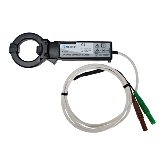
- Page 1 Leakage current clamp A 1472, A1579 User manual Version 1.2, Code no. 20 752 271...
- Page 2 Mark on your equipment certifies that this equipment meets the requirements of the EU (European Union) concerning safety and electromagnetic compatibility regulations. No part of this publication may be reproduced or utilized in any form or by any means without permission in writing from METREL.
-
Page 3: Table Of Contents
A 1472, A1579 Leakage current clamp Warnings ................... 4 Description of leakage current clamp ..........5 Meaning of symbols ..............6 Maintenance ..................7 Inspection ................... 7 Cleaning ..................7 Service and calibration ..............7 Leakage current clamp operation ............ 8 Measuring of leakage currents ............ -
Page 4: Warnings
A 1472, A1579 Leakage current clamp 1 Warnings To ensure a high level of operator's safety during using of the leakage current clamp the following warnings have to be considered: Do not use the current clamp if any damage is noticed! ... -
Page 5: Description Of Leakage Current Clamp
The A 1472 is a 1000/1 ratio leakage current clamp for measuring alternating currents in the range from 0.5 mA to 10 A. The A1472 current clamp is specially designed to be used in combination with METREL DeltaPAT testers. Refer to chapter 5. Technical specification for list of all measuring instruments suitable to work with the A1472 current clamp. -
Page 6: Meaning Of Symbols
A 1472, A1579 Leakage current clamp 2.3 Meaning of symbols Symbol on the current clamp indicates that it is possible to use the current clamp on non-insulated conductors. Symbol on the current clamp indicates possible hazardous live conditions if the required safety measures are ignored. -
Page 7: Maintenance
It is essential that your clamp is regularly calibrated in order to guarantee the technical specification listed in this User manual. We recommend 2- year calibration interval. Metrel encloses an original calibration certificate with every new instrument and current clamp. -
Page 8: Leakage Current Clamp Operation
A 1472, A1579 Leakage current clamp 4 Leakage current clamp operation 4.1 Measuring of leakage currents 4.1.1 Origins of leakage currents Leakage currents are currents driven by active conductors of a distribution system or electrical equipment to earth and/or protective conductors. Leakage currents flow wherever a conductive path (resistance and/or capacitance) is applied between active and earthed conductors/protected parts. -
Page 9: Leakage Currents In Normal Operation
A 1472, A1579 Leakage current clamp 4.1.2 Leakage currents in normal operation Typical leakage currents in normal operation are: Leakage currents caused by input filters in electrical equipment connected between live and earth (filters, monitors). The capacitors in input filters have a capacitance of ca. 10 nF to 100 nF (see Fig.1). ... -
Page 10: Leakage Currents In Fault Conditions
A 1472, A1579 Leakage current clamp 4.1.3 Leakage currents in fault conditions Faults in electrical installations and equipment can cause additional continuous or short-lasting leakage currents. Typical faults that can cause increased leakage currents are: Deterioration of insulation (because of pollution, moisture, corrosion). -
Page 11: Problems Caused By Leakage Currents
A solution is to add RCD(s) and divide the circuits in a way that the leakage currents in normal operation stay below 20% of the nominal value of each RCD. For further information refer to METREL handbook Guide for testing and verification of low voltage installations. - Page 12 A 1472, A1579 Leakage current clamp On Fig.3 two non-sinusoidal leakage currents are shown. Fig.3: Examples of atypical leakage current Impaired safety due to fault, earth, touch voltages Leakage currents that are flowing into earth and PE conductors cause a voltage drop on exposed conductive parts.
-
Page 13: Measuring Leakage Currents With Current Clamps
A 1472, A1579 Leakage current clamp 4.2 Measuring leakage currents with current clamps The simplest way of measuring leakage current is the measurement with leakage current clamps. The measuring principle is shown on Figure 4 and in Equations 3,4. Fig.4: Measuring principle of current clamp – direct and differential method Eq.3 ... -
Page 14: Differential Method
A 1472, A1579 Leakage current clamp 4.2.2 Differential method The sum of currents through two or more active (embraced) conductors is measured in the differential method. If no current is leaking into PE conductors/ earth the sum of currents through active conductors must be exactly zero regardless of the load currents. -
Page 15: Testing Procedures
A 1472, A1579 Leakage current clamp 4.3 Testing procedures 4.3.1 Finding sources of excessive leakage current The described testing procedure in this chapter is applicable for troubleshooting in the installation and electrical equipment in case of nuisance tripping of protective devices. 1. - Page 16 A 1472, A1579 Leakage current clamp By using any of the procedures described above the faulty point can be determined very precisely. Fig. 7: Finding source of excessive leakage current – by disconnection Fig. 8: Finding source of excessive leakage current – measuring downstream the installation...
-
Page 17: Insulation Resistance Testing
A 1472, A1579 Leakage current clamp 4.3.2 Insulation resistance testing The standard high voltage insulation resistance test can sometimes not be carried out – if the installation is not allowed to be disconnect for a longer time or sensitive equipment is connected. In this case the leakage current measurement can conditionally be used as an alternative to the insulation resistance test. -
Page 18: Influencing Quantities
A 1472, A1579 Leakage current clamp 4.4 Influencing quantities Unfortunately measurements with leakage current clamp are subjected to different influencing quantities that have a big impact on their performance. High uncertainty and non-repeatability of readings often lead to wrong interpretations. Three most important influencing quantities are described in this document. -
Page 19: Influence Of External Electric Field
A 1472, A1579 Leakage current clamp 4.4.3 Influence of external electric field The electric field caused by voltage on measured conductors or any other conductors/ parts in vicinity can interact with the current clamp through capacitive coupling. This can happen through the sensor, housing, test cables, measuring instrument etc.. -
Page 20: Consideration Of Influencing Quantities
A 1472, A1579 Leakage current clamp Fig. 11: Minimizing influencing quantities, correct placement of conductors Fig. 12: Minimizing influencing quantities, avoiding external magnetic and electric fields 4.4.6 Consideration of influencing quantities Only high quality current clamp can accurately measure in range of mA in presence of external fields and high load currents. -
Page 21: Other Important Current Clamp Parameters
A 1472, A1579 Leakage current clamp 4.5 Other important current clamp parameters 4.5.1 High measuring range Leakage clamps with a high measuring range can be used for other applications too. A 20 A measuring range will cover most of application in standard residential electrical installations. -
Page 22: Technical Specifications
5 Technical specifications List of instruments that support operation with A 1472 Current clamp is designed to be used in combination with following METREL testers: PAT tester DeltaPAT BT MI 3309 PAT tester DeltaGT BT MI 3309 List of instruments that support operation with A 1579...
Need help?
Do you have a question about the A1472 and is the answer not in the manual?
Questions and answers