
Subscribe to Our Youtube Channel
Related Manuals for Kunz AcrEase MR55KEI


Summary of Contents for Kunz AcrEase MR55KEI
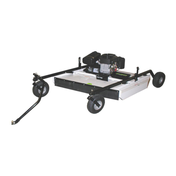
- Page 1 57” ROUGH CUT WITH ELECTRIC CLUTCH BLADE ENGAGEMENT OWNER’S MANUAL With Assembly Instructions For Models: MR55BE, MR55KE-25HP & MR55KEI KUNZ ENGINEERING, INC. / MENDOTA, IL 61342 / PH (815) 539-6954 1/22...
-
Page 3: Table Of Contents
TABLE OF CONTENTS SAFETY INTRODUCTION……………………………………………………………………………… 2 Safety Alert Symbol …………………………………………………………………………………… 2 Safety Information ……………………………………………………………………………………… 3 Safety Signs and Locations ……………………………………………………………………………4 ASSEMBLY INSTRUCTIONS ………………………………………………………………………..5 Items Included ………………………………………………………………………………………….. 5 Assembly of Mower Wheels ………………………………………………………………………….. 5 Installation of Tongue Assembly ……………………………………………………………………... 5 OPERATION AND ADJUSTMENTS ………………………………………………………………….. -
Page 4: Safety Introduction
It may also be used to alert against unsafe practices. This entire manual is filled with important safety information. Please read it carefully. If you have any questions or concerns regarding the information in this owner’s manual please contact Kunz Engineering at 815-539-6954. -
Page 5: Safety Information
IMPORTANT SAFETY INFORMATION Do not allow anyone to operate this equipment who has not fully read and comprehended the safety manual and who has not been properly trained in the safe operation of the equipment. Operator should be familiar with all functions of the unit. Keep hands, feet, hair and clothing away from moving parts. -
Page 6: Safety Signs And Locations
275002 – Warning Decal, General Serial # and Model # Decal Clean or Replace Any Safety Signs That Are not Readable or Damaged Replacement decals can be purchased from your local dealer or Kunz Engineering Inc. Mendota, IL 61342 (815) 539-6954... -
Page 7: Assembly Instructions
ASSEMBLY INSTRUCTIONS Read the complete assembly instructions before starting the assembly. You should have: - one mower deck assembly - two carrier arm assemblies - two rear tire assemblies - one ATV tongue assembly A. ASSEMBLY OF MOWER WHEELS 1. Set the mower deck assembly on wood blocks so that it is suspended off the ground. Note: The operator controls are on the front of the deck. - Page 8 Bolt Carrier Arm Assembly Spanner Tube Flat Washer Hex Nut and Rear Tire Lock Washer Cup Washer Figure 1: Rear Tire Assembly Installation Hitch Pivot – Attach to Tongue Height Adjust Either Left or Right Screw Carrier Arm Assy. Front (Rubber Flap Side) Rear Tire Assy.
-
Page 9: Operation And Adjustments
Direction of Travel Screw Pin Shackle Clevis Shift Tongue Left or Right Between Holes Tongue 5/16” Wire Lock Pins Wire Lock Section of Wire Lock Pin (Placed Back From Direction of Travel) Figure 3: ATV Tongue Assembly OPERATIONS AND ADJUSTMENTS This safety alert symbol is used to indicate safety instructions. -
Page 10: Adjusting Cutting Height
Note: When pulling the mower directly behind, the hitch pivot should be fastened on the right carrier arm for maximum maneuverability. See Figure 2. When pulling the mower in the offset position the hitch pivot can be fastened on either the right or left carrier arm. See Figure 2. - Page 11 Adjust the mower as follows: 1. Pull the mower on to a smooth, level surface. 2. Adjust the mower evenly from side to side by measuring to the ground from the lower edge of the mower deck. The desired height will be the distance from the ground to the outside lower edge of the mower deck plus 1-5/16”.
-
Page 12: Starting Engine
Adjustment Crank Adjustment Nut Tube Carrier Arm Upper Pivot Support Figure 6: Securing Crank While Not In Use C. STARTING ENGINE Set parking brake on tow vehicle. Attach mower tongue to tow vehicle. Do not start rough cut mower unless it is attached to the tow vehicle. Turn on the fuel shut off valve (red colored rotating knob) located inline on the fuel hose. -
Page 13: Shutting Off Mower
D. SHUTTING OFF ROUGH CUT MOWER Shift to neutral and set the parking brake before dismounting the tow vehicle. Slow the engine speed down and disengage the clutch by pushing inward on the PTO switch. Allow engine to cool down for a short time before moving the ignition switch to the off position. Turn off the fuel shut off valve (red colored rotating knob) located inline on the fuel hose. -
Page 14: Maintenance
Stop the mower blades on the mower if the tow vehicle becomes stuck or stops going forward because of loss of traction. Shut off the engine on the mower before attempting to push or pull the tow vehicle. Inspect the ATV Tongue Assembly and tow vehicle hitch before each use. If any parts of the tongue or hitch look damaged or severely worn, discontinue use of the mower until the damaged or worn parts are replaced. -
Page 15: Mower Blade Removal, Balancing & Installation
Install the new belt and then adjust the tension as follows: See Figure 7. Initial Spring Length (New Belt): 2-1/2” to 2-9/16” Running Spring Length: 2-3/4” to 3-1/4” Only Include Front Spring in Measurement Engine/Clutch Figure 7: Belt Pattern and Spring Adjustment Adjust the nuts on the spring-loaded idler adjuster bolt until the length of the spring is between 2- 1/2”... -
Page 16: Lubrication
The Models MR55BE and MR55KE use the Kunz Engineering Part # (202141) blade bolt. This particular hex head bolt is a 3/4” – 16NF x 1-1/4” long, grade 5 and it’s proper torque is 300 ft-lbs. -
Page 17: Specifications
ACREASE ROUGH CUT MOWER SPECIFICATIONS Model Model Model MR55BE MR55KE MR55KEI ENGINE: Engine Make Briggs & Stratton Kohler Kohler Engine Model Commercial Turf Confidant Confidant EFI Cylinders Cycles Crankshaft Vertical Vertical Vertical Engine HP Bore 3.30" 3.30" 3.30" Stroke 2.89" 2.70"... -
Page 18: Service Parts
Control Panel Decal, Starting Instructions 275002 Warning Decal General 275003 Danger Decal, Cut Finger 275007 Warning Decal, Belt Sheild 275019 Name Decal, Kunz 275021 Name Decal, AcrEase 275022 Name Decal, 57" Rough Cut 277002 Rubber Gromet 277035 Gas Cap - Audible Click/Tethered, Non-Venting... - Page 19 Item Part # Description Quantity 600133 Belt Sheild 600142 Upper Pivot Support 600143 Safety Belting 600146 Crank Arm 600172 Engine Support Bracket 600189 Idler Spacer Block 600198 Clutch Stop 600200 Spacer, 1.38" O.D. x 1.33" Wall x 1.00" Long 600290 Canister Support (California Only) 600305 Control Panel...
-
Page 20: Parts Drawing
ACREASE ROUGH CUT MOWER PARTS... -
Page 21: Optional Equipment
OPTIONAL EQUIPMENT OPTIONAL WETLANDS KIT The optional wetlands kit features an extra set of tires for added ground support in soft or water saturated areas. The following are applications and features that the wetlands kit works best in. • Great for wetlands or marshy areas that stay wet all year around. •... -
Page 22: Electric Lift Kit
OPTIONAL EQUIPMENT OPTIONAL ELECTRIC LIFT KIT The optional electric lift kit consists of all of the mounting hardware, brackets, electric actuator and wiring with remote control panel. • Great for constantly changing terrain and grass/brush heights. • Allows for quick cutting height changes on the go from the seat of the tow vehicle. •... -
Page 23: Floatation Kit
OPTIONAL EQUIPMENT OPTIONAL FLOATATION KIT The optional floatation kit consists of one additional front and rear tire, mounting brackets and hardware. • Great for mowing around ponds and on rough uneven ground where scalping would normally occur. • Clamping style receiver allows for adjustments from side to side with both the front and rear tires. -
Page 24: Warranty Statement
AcrEase Pull Behind Mower Warranty Policy Kunz Engineering, Inc., warrants to the owner that each new product is free of defects in workmanship and material for the length of 12 months from the date of purchase. Kunz Engineering, Inc., agrees to provide replacement parts for any defective parts at no charge to the owner.
Need help?
Do you have a question about the AcrEase MR55KEI and is the answer not in the manual?
Questions and answers