
Related Manuals for Kunz AcrEase MR44V


Summary of Contents for Kunz AcrEase MR44V
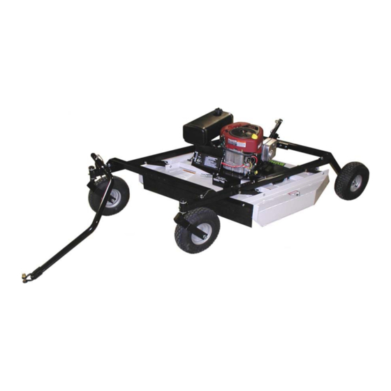
- Page 1 44” ROUGH CUT OWNER’S MANUAL With Assembly Instructions For Models: MR44B & MR44V KUNZ ENGINEERING, INC. / MENDOTA, IL 61342 / PH (815) 539-6954 2/14...
-
Page 2: Safety Introduction
SAFETY INTRODUCTION Your safety, and the safety of others, is very important. To help you make informed decisions about safety, we have provided operating procedures and other information on labels and in this manual. This information alerts you to potential hazards that could hurt you or others. -
Page 3: Important Safety Information
IMPORTANT SAFETY INFORMATION WARNING: Do not allow anyone to operate this equipment who has not fully read and comprehended the safety manual and who has not been properly trained in the safe operation of the equipment. WARNING: Operator should be familiar with all functions of the unit. DANGER: Keep hands, feet, hair and clothing away from moving parts. - Page 4 275002 – Warning Decal, General Serial # and Model # Decal Clean or Replace Any Safety Signs That Are not Readable or Damaged Replacement decals can be purchased from your local dealer or Kunz Engineering Inc. Mendota, IL 61342 (815) 539-6954...
- Page 5 ASSEMBLY INSTRUCTIONS Read the complete assembly instructions before starting the assembly. You should have: - one mower deck assembly - two carrier arm assemblies - two rear tire assemblies - one front cross brace tube and one rear cross brace tube with height adjust assy. - one ATV tongue assembly A.
- Page 6 3. Install the two carrier arm assemblies in the pivot arms, which are located on the mower deck assembly. Place the assembly so that the castered tires are on the front and the fixed tires are on the back. See figure 2. Secure with 1/2" x 3-1/2" hex head bolts and lock nuts provided on the pivot arms.
- Page 7 1/2” x 3” Bolt Height Adjust Assy. Cross Brace Tube Figure 3: Cross Brace Tube Installation Screw Mounting Flat Height Adjust 1/2” x 1” Bolt Assy. Lower Deck Screw Mount Figure 4: Height Adjust Assy. Installation 4. Turn the crank on the height adjust assy. and raise the mower to its highest position. At this time securely tighten the 1/2”...
- Page 8 C. INSTALLATION OF TONGUE ASSEMBLY 1. The tongue can be installed either on the left or right carrier arm assembly depending on how the tow-behind mower will be towed. See figure 5. Secure the hitch pivot on the chosen carrier arm assembly with the 1/2” x 3-1/2” hex head bolt, lock washer, and nut provided. 2.
-
Page 9: Operations And Adjustments
Direction of Travel Screw Pin Shackle Clevis Shift Tongue Left or Right Between Holes Tongue 5/16” Wire Lock Pins Wire Lock Section of Wire Lock Pin (Placed Back From Direction of Travel) Figure 6: ATV Tongue Assembly OPERATIONS AND ADJUSTMENTS This safety alert symbol is used to indicate safety instructions. - Page 10 The tongue is equipped with a screw pin shackle clevis to provide movement in all directions on rough uneven ground. To prevent loss of the screw pin due to vibration or debris, place the screw pin through the tow vehicle hitch and clevis and turn the screw pin until snug. The tongue is designed to adjust from left to right within the hitch pivot.
- Page 11 The cutting height can be adjusted in a range from 2.0" to 8.0". This is accomplished by turning the height adjust crank located at the back of the mower. See Figure 8. Turn the crank clockwise to raise the mower cutting height and counter-clockwise to lower the mower cutting height. DANGER: Shut off tow vehicle engine and allow mower blades to stop completely before attempting to measure the cutting height.
- Page 12 C. STARTING ENGINE WARNING: Set parking brake on tow vehicle. Attach mower tongue to tow vehicle. WARNING: Do not start rough cut mower unless it is attached to the tow vehicle. Turn on fuel shut off valve which is located on the underside of the gas tank. Set the choke to the desired position.
- Page 13 WARNING: Remove all objects from the work area that might be picked up and thrown by the blades. WARNING: Do not mow when children and others are around. WARNING: Do not fill fuel tank while engine is running or hot. WARNING: Keep all safety shields and deflectors in place during operation.
- Page 14 F. DRIVE BELT REMOVAL AND TENSION – Refer to Figure 10 WARNING: Shut off engine and allow mower blades to stop turning before making any adjustments or repairs. Remove the safety shields. Loosen the nuts on the spring-loaded idler; adjust bolt until the belt can be slipped off the idler and drive sheaves.
- Page 15 Always shut mower engine off before servicing. Under normal operating conditions and when using the Kunz Engineering belt (Part # 238007) the brake stud should require very little adjustment. Periodic brake stud inspections should be performed every 10 hours.
- Page 16 The Models MR44B and MR44V use the Kunz Engineering Part # (202141) blade bolt. This particular hex head bolt is a 3/4” – 16NF x 1-1/4” long, grade 5 and its proper torque is 300 ft-lbs.
- Page 17 / fuel vapor valve, carbon canister (California Only) and hose clamps are prohibited. Replacement evaporative components should be purchased from Kunz Engineering. Any questions about EPA regulations or evaporative components can be directed to Kunz Engineering Inc. at 815-539-6954.
- Page 18 ACREASE ROUGH CUT MOWER SPECIFICATIONS Model Model MR44B MR44V ENGINE: Engine Make Briggs & Stratton Briggs & Stratton Commercial Engine Model Intek Professional Vanguard Cylinders Cycles Crankshaft Vertical Vertical Engine HP Bore 3.12" 2.84" Stroke 3.06" 2.76" Displacement 33.0 cu. In. 34.78 cu.
- Page 19 Control Panel Decal, Starting Instructions 275002 Warning Decal General 275003 Danger Decal, Cut Finger 275007 Warning Decal, Belt Sheild 275011 Clutch Engagement Decal 275019 Name Decal,Kunz 275021 Name Decal, AcrEase 275024 Name Decal, 44" Rough Cut 277002 Rubber Gromet 277011 Handle Grip 277035...
- Page 20 Item Part # Description Quant ity 600185 Top Lon g Support 600186 Top Shor t Support 600252 Flap Reta iner Strip 600253 Safety Belting 600254 Battery Box Spacer 600264 Belt Sheil d, Left 600265 Belt Sheil d, Ri ght 600268 Hei ght Adjust Support 600291 Canister Support (California Only)
- Page 21 ACREASE 44” ROUGH CUT MOWER PARTS...
-
Page 22: Optional Equipment
OPTIONAL EQUIPMENT OPTIONAL WETLANDS KIT The optional wetlands kit features an extra set of tires for added ground support in soft or water saturated areas. The following are applications and features that the wetlands kit works best in. • Great for wetlands or marshy areas that stay wet all year around. •... - Page 23 OPTIONAL EQUIPMENT OPTIONAL ELECTRIC LIFT KIT The optional electric lift kit consists of all of the mounting hardware, brackets, electric actuator and wiring with remote control panel. • Great for constantly changing terrain and grass/brush heights. • Allows for quick cutting height changes on the go from the seat of the tow vehicle. •...
- Page 24 OPTIONAL EQUIPMENT OPTIONAL FLOATATION KIT The optional floatation kit consists of one additional front and rear tire, mounting brackets and hardware. • Great for mowing around ponds and on rough uneven ground where scalping would normally occur. • Clamping style receiver allows for adjustments from side to side with both the front and rear tires.
Need help?
Do you have a question about the AcrEase MR44V and is the answer not in the manual?
Questions and answers