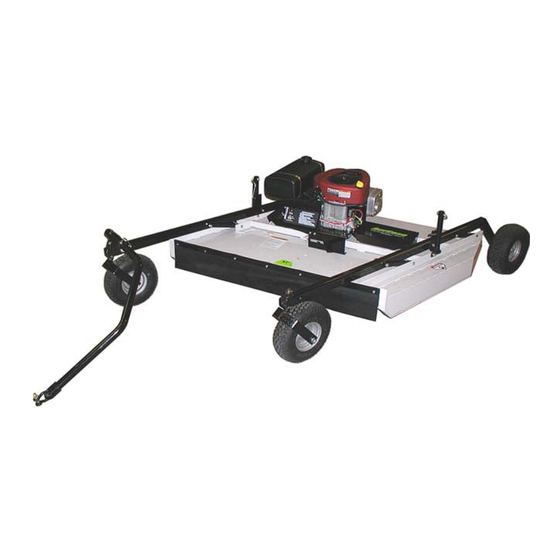
Kunz MR55B Owner's Manual
57” rough cut
Hide thumbs
Also See for MR55B:
- Owner's manual (23 pages) ,
- Owner's manual with assembly instructions (18 pages)

Related Manuals for Kunz MR55B


Summary of Contents for Kunz MR55B
- Page 1 57” ROUGH CUT MR55K MR55B OWNER’S MANUAL With Assembly Instructions For Models: MR55T, MR55B-17.5HP, MR55B-22-23HP & MR55K KUNZ ENGINEERING, INC. MENDOTA, IL 613 PH (815) 539-6954 1/09...
-
Page 2: Safety Introduction
SAFETY INTRODUCTION Your safety, and the safety of others, is very important. To help you make informed decisions about safety, we have provided operating procedures and other information on labels and in this manual. This information alerts you to potential hazards that could hurt you or others. -
Page 3: Important Safety Information
IMPORTANT SAFETY INFORMATION WARNING: Do not allow anyone to operate this equipment who has not fully read and comprehended the safety manual and who has not been properly trained in the safe operation of the equipment. WARNING: Operator should be familiar with all functions of the unit. DANGER: Keep hands, feet, hair and clothing away from moving parts. - Page 4 Clean or R eplace Any Safety Signs That Are not Readable or Damaged Replacement decals can be purchased from your local dealer or 275003 – Danger Decal, Cut Hand & Foot Kunz Engineering Inc. Mendota, IL 61342 (815) 539-6954 275007 – Warning...
-
Page 5: Assembly Instructions
Read the complete assembly instructions before starting the assembly. You should have: - one mower deck assembly - two carrier arm assemblies - two rear tire assemblies - one ATV tongue assembly A. ASSEMBLY OF MOWER WHEELS 1. Set the mower deck assembly on wood blocks so that it is suspended off the ground. Note: The operator controls are on the front of the deck. - Page 6 rrier Arm sembly Hex Nut and Lock Washer Cup Washer Figure 1: Rear Tire Assembly Installation Hitch Pivot – Attach to Either Left or Right Carrier Arm Assy. Carrier Arm ssy. Offset Position Figure 2: Assembly of Carrier Arm Assy., Hitch Pivot, and Tongue Rear Tire Flat Washer Tongue...
- Page 7 Direction of Travel Shift Tong ue Left or Right Between Hol 5/16” Wire Lock Pins OPERA This safety alert symbol is used to these instructions to avoid personal Read and follo manual. WARNING : Do not allow anyone to operate this equipment who has not fully read and comprehended the safety manual and who has not been properly trained in the safe operation of the equipment.
-
Page 8: Adjusting Cutting Height
The tongue is equipped with a screw pin shackle clevis to provide movement in all directions on rough uneven ground. To prev pin through the tow vehicle hitch and clevis and turn the screw pin until snug. The tongue is designed to adjust from left to right within the hitch pivot. This allows the mowers position to be varied behind the tow vehicle. - Page 9 The cutting height can be adjusted in a range from 2.0" to 8.0". This is accomplished by turning the height adjust cranks on both sides of the mower. See Figure 5. Turn the cranks clockwise to raise the mower cutting height and counter-clockwise to lower the mower cutting height. DANGER: Shut off tow vehicle engine and allow mower blades to stop completely before attempting to measure the cutting height.
-
Page 10: Starting Engine
C. STAR ING ENGINE WARNING : Set parking brake on tow vehicle. Attach mower tongue to tow vehicle. WARNING: Do not start rough cut mower unless it is attached to the tow vehicle. n on fuel shut off valve which is located the choke to the desired position. - Page 11 WARNING: Remove all objects from the work area that might be picked up and thrown by the blades. WARNING: Do not mow when children and others are around. WARNING: Do not fill fuel tank while engine is running or hot. WARNING: Keep all safety shields and deflectors in place during operation.
- Page 12 F. DRIVE BELT REMOVAL AND TENSION – Refer to Figure 7 WARNING: Shut off engine and allow mower blades to stop turning before m adjustments or repairs. Remov e the safety shields. Loosen the nuts on the spring-loaded idler; adjust bolt until the belt can be slipped off the idler and drive s eaves.
- Page 13 provide the appropriate braking force. If the spring length is to long it will be necessary to adjust the brake stud closer to the belt. If the spring length is to short it will be necessary to adjust the brake stud further away from the belt. To make brake stud adjustments loosen the bolt on the top of the brake stud and slide the brake stud in the slot.
- Page 14 The Models MR55K, MR55B and MR55T use the Kunz Engineering Part # (202141) blade bolt. This particular hex head bolt is a 3/4” – 16NF x 1-1/4” long, grade 5 and it’s proper torque is 300 ft-lbs.
- Page 15 C UTCH TYPE Engagement Speed DIMENSIONS ngth Height Weight HITCH Hitch Type TOUCH-UP PAINT COLOR Model Model MR55T MR55B-17.5HP Tecumseh Briggs & Stratton Enduro OHV 170-EXE Intek AVS OHV Vertical Vertical 17.5 3.56” 3.57" 3.00” 3.06" 29.9 cubic inches 30.6 cubic inches...
- Page 16 Fuel Tank, 3.75 Gal. (Plastic)(Use Gas Cap 277013) 277011 Handle Grip 277013 Gas Cap (For Fuel Tank 277010) 600071 Spacer, 1.38" O.D. x 1.33" Wall x 2.19" Long (MR55B & MR55T) 600173 Spacer, 1.38" O.D. x 1.33" Wall x 2.25" Long (MR55K) 600126 Flap Retainer Strip 600133...
- Page 17 Idler Arm Assy. 243005 Bronze Bearing, 1/2"I.D. x 3/4" O.D. x .75" Long 900066 Screw Adjuster 900069 Mower Deck 900071 Engine Support Bracket (Model MR55B-17.5HP & MR55T) 600172 Engine Support Bracket (Model MR55K & MR55B-22-23HP) 900079 Tank Support 900082 Tongue 900106...
- Page 18 A CREASE ROUGH CUT MOWER PARTS...
-
Page 19: Optional Equipment
OPTIONAL WETLANDS KIT The optional wetlands kit features an extra set of tires for added ground support in soft or water saturated areas. The following are applications and features that the wetlands kit works best in. • Great for wetlands or marshy areas that stay wet all year around. •... - Page 20 OPTIONAL ELECTRIC LIFT KIT The optional electric lift kit consists of all of the mounting hardware, brackets, electric actuator and wiring with remote control panel. • Great for constantly changing terrain and grass/brush heights. • Allows for quick cutting height changes on the go from the seat of the tow vehicle. •...
- Page 21 OPTIONAL FLOATATION KIT The optional floatation kit consists of one additional front and rear tire, mounting brackets and hardware. • Great for mowing around ponds and on rough uneven ground where scalping would normally occur. • Clamping style receiver allows for adjustments from side to side with both the front and rear tires.
Need help?
Do you have a question about the MR55B and is the answer not in the manual?
Questions and answers