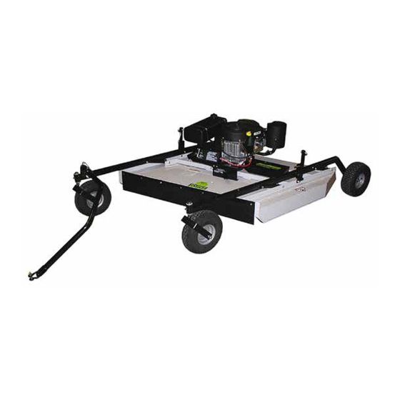
Kunz AcrEase MR55B Owner's Manual
57” rough cut
Hide thumbs
Also See for AcrEase MR55B:
- Owner's manual (21 pages) ,
- Owner's manual with assembly instructions (18 pages)

Subscribe to Our Youtube Channel
Related Manuals for Kunz AcrEase MR55B


Summary of Contents for Kunz AcrEase MR55B
- Page 1 57” ROUGH CUT OWNER’S MANUAL With Assembly Instructions For Model: MR55B KUNZ ENGINEERING, INC. / MENDOTA, IL 61342 / PH (815) 539-6954 1/18...
- Page 2 dfgdfgdfgdfgdfg...
-
Page 3: Safety Introduction
SAFETY INTRODUCTION Your safety, and the safety of others, is very important. To help you make informed decisions about safety, we have provided operating procedures and other information on labels and in this manual. This information alerts you to potential hazards that could hurt you or others. -
Page 4: Important Safety Information
IMPORTANT SAFETY INFORMATION WARNING: Do not allow anyone to operate this equipment who has not fully read and comprehended the safety manual and who has not been properly trained in the safe operation of the equipment. WARNING: Operator should be familiar with all functions of the unit. DANGER: Keep hands, feet, hair and clothing away from moving parts. - Page 5 275002 – Warning Decal, General Serial # and Model # Decal Clean or Replace Any Safety Signs That Are not Readable or Damaged Replacement decals can be purchased from your local dealer or Kunz Engineering Inc. Mendota, IL 61342 (815) 539-6954...
-
Page 6: Assembly Instructions
ASSEMBLY INSTRUCTIONS Read the complete assembly instructions before starting the assembly. You should have: - one mower deck assembly - two carrier arm assemblies - two rear tire assemblies - one ATV tongue assembly A. ASSEMBLY OF MOWER WHEELS 1. Set the mower deck assembly on wood blocks so that it is suspended off the ground. Note: The operator controls are on the front of the deck. - Page 7 Bolt Carrier Arm Assembly Spanner Tube Flat Washer Hex Nut and Rear Tire Lock Washer Cup Washer Figure 1: Rear Tire Assembly Installation Hitch Pivot – Attach to Tongue Height Adjust Either Left or Right Screw Carrier Arm Assy. Front (Rubber Flap Side) Rear Tire Assy.
-
Page 8: Operations And Adjustments
Direction of Travel Screw Pin Shackle Clevis Shift Tongue Left or Right Between Holes Tongue 5/16” Wire Lock Pins Wire Lock Section of Wire Lock Pin (Placed Back From Direction of Travel) Figure 3: ATV Tongue Assembly OPERATIONS AND ADJUSTMENTS This safety alert symbol is used to indicate safety instructions. -
Page 9: Adjusting Cutting Height
The tongue is equipped with a screw pin shackle clevis to provide movement in all directions on rough uneven ground. To prevent loss of the screw pin due to vibration or debris, place the screw pin through the tow vehicle hitch and clevis and turn the screw pin until snug. The tongue is designed to adjust from left to right within the hitch pivot. - Page 10 The cutting height can be adjusted in a range from 2.0" to 8.0". This is accomplished by turning the height adjust cranks on both sides of the mower. See Figure 5. Turn the cranks clockwise to raise the mower cutting height and counter-clockwise to lower the mower cutting height. DANGER: Shut off tow vehicle engine and allow mower blades to stop completely before attempting to measure the cutting height.
-
Page 11: Starting Engine
C. STARTING ENGINE WARNING: Set parking brake on tow vehicle. Attach mower tongue to tow vehicle. WARNING: Do not start rough cut mower unless it is attached to the tow vehicle. Turn on the fuel shut off valve (red colored rotating knob) located inline on the fuel hose. The off position on the valve is when the red handle lines up with the “O”... - Page 12 WARNING: Remove all objects from the work area that might be picked up and thrown by the blades. WARNING: Do not mow when children and others are around. WARNING: Do not fill fuel tank while engine is running or hot. WARNING: Keep all safety shields and deflectors in place during operation.
- Page 13 F. DRIVE BELT REMOVAL AND TENSION – Refer to Figure 7 WARNING: Shut off engine and allow mower blades to stop turning before making any adjustments or repairs. Remove the safety shields. Loosen the nuts on the spring-loaded idler; adjust bolt until the belt can be slipped off the idler and drive sheaves.
- Page 14 of the brake stud and slide the brake stud in the slot. When the proper disengaged spring length is achieved, tighten the bolt on the top of the brake stud. For this procedure do not adjust the spring length. The spring length should only be changed when adjusting the belt tension. Brake Stud Clearance: This inspection is necessary to prevent over-braking.
- Page 15 The Model MR55B uses the Kunz Engineering Part # (202141) blade bolt. This particular hex head bolt is a 3/4” – 16NF x 1-1/4” long, grade 5 and it’s proper torque is 300 ft-lbs.
- Page 16 ACREASE ROUGH CUT MOWER SPECIFICATIONS Model MR55B ENGINE: Engine Make Briggs & Stratton Engine Model Commercial Turf OHV Cylinders Cycles Crankshaft Vertical Engine HP Bore 3.12" Stroke 2.89" Displacement 44.2 cubic inches Oil Capacity 2 U.S. qt Crankshaft Dia. 1.0" Key Slot 1/4"...
- Page 17 Control Panel Decal, Starting Instructions 275002 Warning Decal General 275003 Danger Decal, Cut Finger 275011 Clutch Engagement Decal 275007 Warning Decal, Belt Sheild 275019 Name Decal,Kunz 275021 Name Decal, AcrEase 275022 Name Decal, 57" Rough Cut 277002 Rubber Gromet 277011 Handle Grip 277035...
- Page 18 Item Part # Description Quantity 600071 Spacer, 1.38" O.D. x 1.33" Wall x 2.19" Long 600126 Flap Retainer Strip 600133 Belt Sheild 600136 Brake Stud 600142 Upper Pivot Support 600143 Safety Belting 600146 Crank Arm 600172 Engine Support Bracket 600189 Idler Spacer Block 600290 Canister Support (California Only)
- Page 19 ACREASE ROUGH CUT MOWER PARTS...
-
Page 20: Optional Equipment
OPTIONAL EQUIPMENT OPTIONAL WETLANDS KIT The optional wetlands kit features an extra set of tires for added ground support in soft or water saturated areas. The following are applications and features that the wetlands kit works best in. · Great for wetlands or marshy areas that stay wet all year around. ·... - Page 21 OPTIONAL EQUIPMENT OPTIONAL ELECTRIC LIFT KIT The optional electric lift kit consists of all of the mounting hardware, brackets, electric actuator and wiring with remote control panel. · Great for constantly changing terrain and grass/brush heights. · Allows for quick cutting height changes on the go from the seat of the tow vehicle. ·...
- Page 22 OPTIONAL EQUIPMENT OPTIONAL FLOATATION KIT The optional floatation kit consists of one additional front and rear tire, mounting brackets and hardware. · Great for mowing around ponds and on rough uneven ground where scalping would normally occur. · Clamping style receiver allows for adjustments from side to side with both the front and rear tires.
Need help?
Do you have a question about the AcrEase MR55B and is the answer not in the manual?
Questions and answers