Table of Contents
Advertisement
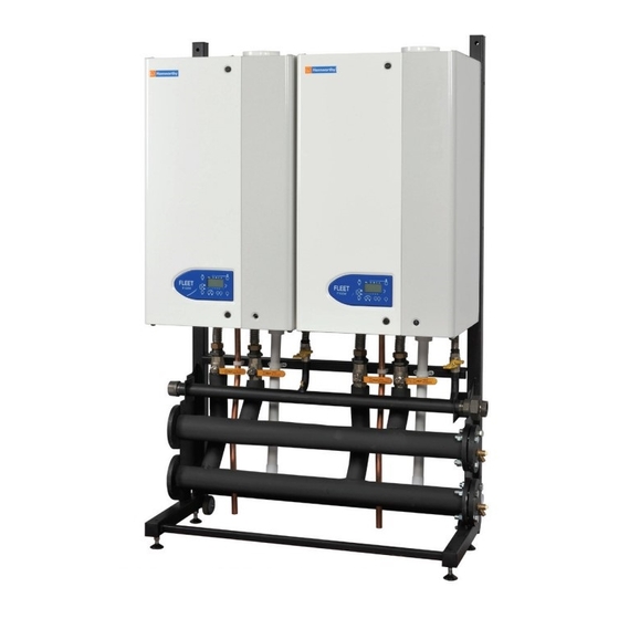
FLEET SERIES BOILERS
Wall Hung, Condensing , Room Sealed,
Fully Modulating, Pre-Mix,
Gas Fired Boilers for Heating & Domestic
Hot Water Installations
Installation, Commissioning
and Operating Instructions
Models: F40W, F50W, F60W, F70W, F85W, F100W,
F125W & F150W
NATURAL GAS I
2H
IMPORTANT NOTE
THESE INSTRUCTIONS MUST BE READ
AND UNDERSTOOD BEFORE INSTALLING,
COMMISSIONING, OPERATING OR
SERVICING EQUIPMENT
Advertisement
Table of Contents


Need help?
Do you have a question about the FLEET Series and is the answer not in the manual?
Questions and answers