
Subscribe to Our Youtube Channel
Related Manuals for Hamworthy Stratton mk3


Summary of Contents for Hamworthy Stratton mk3
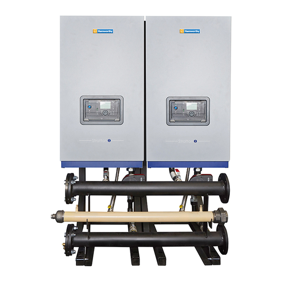
- Page 1 Stratton mk3 40 - 70 kW Frame and Header Kits Manual IMPORTANT NOTE THESE INSTRUCTIONS MUST BE READ AND UNDERSTOOD BEFORE INSTALLING, COMMISSIONING, OPERATING OR SERVICING EQUIPMENT UIN 233246 A01...
-
Page 2: Table Of Contents
This kit is suitable for the following boilers: Stratton mk3 40, 60 & 70 using both Natural Gas and Propane CONTENTS 1 Introduction ..............3 2 General Description Of Systems........4 3 System Components ............6 4 Installation Procedure ............8 5 Installation Drawings For Boiler Systems....14 6 Electrical Connections &... -
Page 3: Introduction
INTRODUCTION This technical data contains information for dimensioning and assembly of a cascade system kit for the Stratton mk3 ranges. These 40-70kW kits are supplied with gas and water header kits designed for use with a low loss header system. -
Page 4: General Description Of Systems
3000 x 685 x 1418 DN50 232864 * Max 5 x 60 kW only ** Max 6 x 40 kW only Available Appliances Product No. Stratton mk3 S 3 40 AA082635 Stratton mk3 S 3 60 AA082636 Stratton mk3 S 3 70 AA082637 Note. - Page 5 2.2 MULTIPLE BOILER INSTALLATIONS When sizing multiple appliance installations, the minimum and maximum system heat load requirements need to be matched to the minimum and maximum appliance load capabilities. These water header & pump kits are design to supply the optimum water flow around the appliance water circuit only and must be used in conjunction with a suitably sized low loss header (mixing header) or plate heat exchanger.
-
Page 6: System Components
Incorporating all the required mountings and assembly systems Hamworthy recommend:- DN50 – 232875. to bolt up to four frames together in a side by side format and mount the relevant water and gas heater kits. - Page 7 IMPORTANT POINTS Before commencing installation: If Wall mounting; • Ensure wall is capable of supporting the weight of boilers to be mounted • Mark drill points of header using the frame as a guide. • Mark height on to the wall from the floor to the top of the boiler •...
-
Page 8: Installation Procedure
INSTALLATION PROCEDURE 4.1 WALL MOUNTED SIDE BY SIDE OPTION Ensure wall is capable of supporting the weight of boilers to be mounted. Note. boiler weights can found in the boiler Installation Instructions. 1. Cut the sides off the cardboard wall mounting template/s (found in the boiler packaging) to create the 50mm side clearance required. - Page 9 4.1 WALL MOUNTED SIDE BY SIDE OPTION CONT'D.... SIDE VIEW PLAN VIEW HEADER All dimensions in mm Careful consideration MUST be given to the installation tolerances. See Section 3.7. if these are not adhered to, hoses may become kinked or connections may not fit. 40 - 70 kW Frame and Header Kits Manual...
- Page 10 4.2 SIDE BY SIDE FRAME KIT MOUNTING PROCEDURE 1. Place the frame kit sections in the required position and bolt them together at the top and bottom with the bolts, nuts and washers provided. 2. Drill and fit the required floor bolt's (not provided) through the hole provided in the front of the frame feet. (Note, this must be done before fitting water headers) IMPORTANT: MOUNTING FRAME MUST BE SECURED TO THE FLOOR WITH BOLTS 40 - 70 kW Frame and Header Kits Manual...
- Page 11 4.3 BOILER MOUNTING 1. As appropriate mount the boilers onto either the wall plates or the side by side frame kit. 4.4 BOILER ASSEMBLY 1. Attach flow connection assembly to the boiler flow 4. Attach flow connection assembly to the boiler return connection using suitable jointing compound.
- Page 12 4.5 HEADER KIT ASSEMBLY (OPTIONAL ACCESSORY) FITTING MIXING HEADER AND BLANKING FLANGES 1. Fit the mixing header and blanking flanges in the chosen positions. Note. Mixing header can be located either LHS or RHS of the headers. Blanking Flange Mixing Header 4.6 HEADER ASSEMBLY 4.7 FITTING THE GAS HEADER 1.
- Page 13 4.8 ASSEMBLE HEADER ONTO FRAME 1. Tighten the header bolts onto the frame. 2. Ensure that the test points on the gas header are accessible. Note: The test point nearest the inlet to the rigs is deemed as the appliance pressure test point for the appliances fitted).
-
Page 14: Installation Drawings For Boiler Systems
INSTALLATION DRAWINGS FOR BOILER SYSTEMS 5.1 GENERAL The boiler and pipekit systems are available in side by side format: • 1 to 6 boilers in a linear configuration, mounted on a free-standing frame. These boiler and cascade systems are sized to provide a flow and return differential of 20º∆T. 5.2 INSTALLATION DRAWING WITH 1 40-70 kW BOILER (LOW LOSS HEADERS OR PLATE HEAT EXCHANGERS SYSTEM FLOW... - Page 15 5.4 INSTALLATION DRAWING WITH 3 40-70 kW BOILERS (LOW LOSS HEADERS OR PLATE HEAT EXCHANGERS) 1500 SYSTEM FLOW DN50 PN6 FLANGE SYSTEM RETURN DN50 PN6 FLANGE NOTE: LOW LOSS HEADER AND GAS CONNECTIONS CAN BE LOCATED EITHER ON THE LH OR RH SIDE OF THE ASSEMBLY TO SUIT THE REQUIREMENT OF THE INSTALLATION All dimensions in mm 5.5 INSTALLATION DRAWING WITH 4 40-70 kW BOILERS...
- Page 16 EITHER ON THE LH OR RH SIDE OF THE ASSEMBLY TO SUIT THE REQUIREMENT OF THE INSTALLATION All dimensions in mm TITLE MATERIAL DRAWN BY CHECKED BY 5 WIDE 40 70 DN50 STRATTON MK3 ECN No. FINISH DRG. SB22736A DATE ALL DIMENSIONS IN MM 5.7 INSTALLATION DRAWING WITH 6 40 kW BOILERS...
-
Page 17: Electrical Connections & Wiring Diagram
ELECTRICAL CONNECTIONS & WIRING DIAGRAM 40 - 70 kW Frame and Header Kits Manual... -
Page 18: Commissioning And Testing
COMMISSIONING AND TESTING 1. Electrical and gas safety checks must be carried out on completion of installation as with individual boiler commissioning. 2. Pump setting - follow the instructions supplied with the pump, referring to the installation manual. FIRST THIS DRAWING REFERENCES A 3D FILE OF THE SAME THIS DOCUMENT IS COPYRIGHT PROTECTED BY IDEAL BOILERS. - Page 19 NOTES 40 - 70 kW Frame and Header Kits Manual...
- Page 20 BH17 0NF Telephone: 01202 662500 Fax: 01202 662522 Email: service@hamworthy-heating.com Website: www.hamworthy-heating.com 40 - 70 kW Frame and Header Kits Manual Hamworthy reserves the right to make changes and improvements which may necessitate alteration to the specification without prior notice.
Need help?
Do you have a question about the Stratton mk3 and is the answer not in the manual?
Questions and answers