Table of Contents
Advertisement
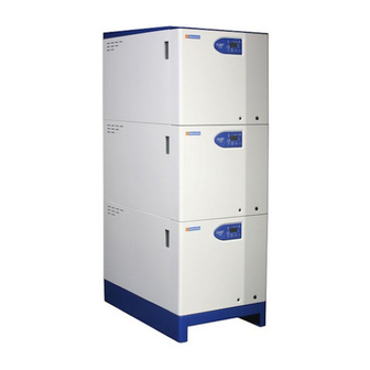
FLEET SERIES BOILERS
Floor Standing, Condensing , Room Sealed,
Fully Modulating, Pre-Mix,
Gas Fired Boilers for Heating & Domestic
Hot Water Installations
Installation, Commissioning
and Operating Instructions
Models: F40H, F50H, F60H, F70H, F85H, F100H,
F125H & F150H
NATURAL GAS I
2H
IMPORTANT NOTE
THESE INSTRUCTIONS MUST BE READ
AND UNDERSTOOD BEFORE INSTALLING,
COMMISSIONING, OPERATING OR
SERVICING EQUIPMENT
Advertisement
Table of Contents

Related Manuals for Hamworthy F40H


Summary of Contents for Hamworthy F40H
- Page 1 Fully Modulating, Pre-Mix, Gas Fired Boilers for Heating & Domestic Hot Water Installations Installation, Commissioning and Operating Instructions Models: F40H, F50H, F60H, F70H, F85H, F100H, F125H & F150H NATURAL GAS I IMPORTANT NOTE THESE INSTRUCTIONS MUST BE READ AND UNDERSTOOD BEFORE INSTALLING,...
- Page 3 Gas Fired Boilers for Heating & Domestic Hot Water Installations Installation, Commissioning and Operating Instructions Models: F40H, F50H, F60H, F70H, F85H, F100H, F125H & F150H NATURAL GAS I NOTE: THESE INSTRUCTIONS MUST BE READ AND UNDERSTOOD BEFORE INSTALLING, COMMISSIONING, OPERATING OR SERVICING EQUIPMENT.
-
Page 4: Table Of Contents
Initial Lighting Combustion Checks User Instructions BOILER CONTROLS ........................24 Controls Operation Functions FAULT FINDING ..........................40 10.0 SERVICING ............................42 11.0 REPLACEMENT OF FAILED COMPONENTS ................44 12.0 RECOMMENDED SPARES ......................45 Page HAMWORTHY HEATING LTD FLEET H Series 500001212/G... - Page 5 Water flow switch ........................40 Figure 9.3.1 Wiring Schematic ........................41 Figure 10.2 Combustion chamber ......................43 Figure 10.2.1 Spark electrode position ......................43 Figure 10.2.2 Flame sensing probe position ....................43 Page HAMWORTHY HEATING LTD FLEET H Series 500001212/G...
- Page 6 Pump performance curves ..................... 65 Figure E2 Typical pipe kit system connections ..................66 Figure F1 Hydraulic diagram 02 ......................67 Figure F2 Hydraulic diagram 80 ......................67 Figure F3 Hydraulic diagram 50 ......................68 Page HAMWORTHY HEATING LTD FLEET H Series 500001212/G...
-
Page 7: Introduction
No draught diverter is fitted to the boiler nor is a fixed diverter required in the flue system. 1.8.2.2 Clip in module (LPB Bus) However, for B23 applications, the Hamworthy air inlet Allows communication with multiple boilers under the filter MUST be used to provide the correct clean air control of a Merley Boiler Sequence Controller. -
Page 8: Supply And Delivery
Appendix C. Warranty Full warranty assistance will be covered when the appliance is commissioned by Hamworthy Heating Ltd, see Terms & Conditions for full details. Hamworthy Heating Ltd will not accept any liability resulting from damage due to tampering, improper use, handling, installation errors, operation and maintenance. - Page 9 Where pipe work kits are supplied, these are packaged separately from the boilers. All ancillary items such as isolation valves and boiler make-up connectors are factory fitted and tested The whole is shrink wrapped for security and basic protection. Refer to Kit instructions 500005133 for specific information. HAMWORTHY HEATING LTD FLEET H series 500001212/F...
-
Page 10: Size And Space Requirements
Note: - the location of the room sealed flue connection is to accommodate the H series pipe work kit, which is located above the boiler casing. If this kit is not being utilised, the height of the connection can be reduced. HAMWORTHY HEATING LTD FLEET H series... - Page 11 1085 max Figure 3.1.2 - Clearances for horizontal flues Note * relates to the use of the Hamworthy H series pipe work kit. This can be reduced if the pipe work is behind the boiler. Figure 3.1.3 - Clearances for vertical flues Note * relates to the use of the Hamworthy H series pipe work kit.
- Page 12 3.2 The Hamworthy Heating Ltd frame set and pipe work kit is designed to provide a compact solution for connecting the boilers to the gas supply and flow and return water connections. The kit locates the pipe work above the boiler casing.
- Page 13 Flow Primary Flow Secondary Primary Return Return Single secondary circuit Secondary Flows Pockets for temperature sensors * 2 Primary Secondary Flow Returns Primary Return Three secondary circuits Sensor Pocket ½” BSP Instrument Spool HAMWORTHY HEATING LTD FLEET H series 500001212/F...
- Page 14 2250 2300 Figure 3.2.4 – Three boilers 3000 3050 Figure 3.2.5 – Four boilers HAMWORTHY HEATING LTD FLEET H series 500001212/F...
-
Page 15: Site Location And Preparation
17.5mbar) dynamic - refer to Appendix A Boiler house gas isolation valve must be clearly identified and installed close to the entrance / exit. Gas connection Figure 4.2 - Gas Connection Point HAMWORTHY HEATING LTD FLEET H series 500001212/F... -
Page 16: Flue System
For external flue runs and termination, either use the dedicated kits supplied by Hamworthy or refer to a chimney specialist . Flue termination, routing and construction must comply with the requirements of the ... - Page 17 Vertically from a terminal on the same wall 1500 Horizontally from a terminal on the same wall From the wall on which the terminal is mounted From a vertical structure on the roof Above intersection with roof HAMWORTHY HEATING LTD FLEET H series 500001212/F...
- Page 18 Maximum working water pressure is 5.3bar. For minimum water pressure 0.5 bar - refer to Appendix E Flow water connection Return water connection Safety Valve Figure 4.4 - Water Connection Points HAMWORTHY HEATING LTD FLEET H series 500001212/F...
- Page 19 Compliance with the manufacturer’s recommendations as detailed in the operating and maintenance manual, ensuring that the commissioning is carried out by either Hamworthy Heating Limited or a competent engineer. To ensure that the settings and checks noted on the commissioning sheet (included in the maintenance manual) are recorded and detailed within the boiler log book.
- Page 20 Boiler gas configuration or type which is not appropriate to the type of gas approved for the appliance. Damage caused by use of spare parts not compatible with the product. Operation of the product at system pressures above that for which it was designed and manufactured. HAMWORTHY HEATING LTD FLEET H series 500001212/F...
-
Page 21: Condensate Connections
Condense is mildly acidic, typically pH3 - pH5. Condense pipe work must be non-corrosive and not copper. Hamworthy recommend plastic waste pipe. Condense may be discharged to a standard drain subject to National or Local ... - Page 22 & trap Tundish to drain Horizontal Concentric Flue System Single pipe inline drain & trap Tundish to drain Vertical Concentric Flue System Conventional Chimney Flue System Figure 4.5.2 - Flue Condensate Connection and discharge HAMWORTHY HEATING LTD FLEET H series 500001212/F...
-
Page 23: Electrical Supply
NOTE: The appliance must be isolated from the electrical supply if electric arc welding is carried out on connecting pipe work. FOR TYPICAL SCHEMATIC DETAILS SEE FIGURE 4.6 FOR DETAILED WIRING INSTRUCTIONS SEE FIGURES 9.3.1 AND APPENDIX B Figure 4.6 - Wiring Schematic HAMWORTHY HEATING LTD FLEET H series 500001212/F... -
Page 24: Boiler Assembly
5.3 Flue Connection 5.3.1 The Hamworthy Fleet boiler is designed for use with the following flue systems supplied by Hamworthy - see Appendix C 80/125mm concentric room sealed, balanced flue system for rear/side through the wall discharge. 100/150mm concentric, room sealed, balanced flue system for remote discharge, horizontal or vertical. -
Page 25: Electrical Connections
Figure 4.3.2. In the case of twin duct applications (C53), air supply inlets must be positioned at least 300 mm from flue terminals to prevent flue gas re-circulation. Hamworthy Heating recommend that flue terminals discharges are positioned higher than air inlets. -
Page 26: Checks Prior To Lighting
Where using Hamworthy Heating Ltd frame set and pipe work kits, assembly of these is detailed in Installation manual 500005133 supplied with kit. -
Page 27: Checks Prior To Lighting The Boiler
11 Check that the boiler controls wiring has not been display screen. The value is set to read dc μA. Refer to modified. Any modification could lead to boiler failure. section 8.2.1.2 - Controls Operation. HAMWORTHY HEATING LTD FLEET H series 500001212/F... -
Page 28: Combustion Checks
3. Insert probe horizontally into the flue elbow until depth stop is met. Figure 7.6 - Combustion Analyser Probe Setting (Note: readings taken with front cover removed and 50mm probe insertion CO = < 80 ppm). HAMWORTHY HEATING LTD FLEET H series 500001212/F... - Page 29 If combustion readings are outside target range use Torx Bit to make adjustments To increase the CO level, turn the adjustment clockwise. Figure 7.6.4 - Adjusting gas valve offset Fig 7.6.1 - Combustion settings HAMWORTHY HEATING LTD FLEET H series 500001212/F...
-
Page 30: Boiler Controls
CONTACT HAMWORTHY HEATING TECHNICAL DEPARTMENT FOR FURTHER DETAILS 7. Shut down the boiler and isolate from the electrical supply. Remove instrumentation and replace test points and plugs. -
Page 31: User Instructions
Commissioning guide, the servicing instructions manual and the user’s instructions should then be handed over and be kept in a safe place for future reference. Figure 8.2.1.1 - Fascia Label Legend Display Screen Keypad Figure 8.2.1.2 -Overview of Fascia Panel HAMWORTHY HEATING LTD FLEET H series 500001212/F... - Page 32 Flue Gas Temperature Sensor - in flue elbow 230v Mains Display Return On/Off switch Pump Gas Valve Low Gas Supply Screen Temperature Pressure Switch Sensor Figure 8.1.6 - General Overview of Boiler Controls HAMWORTHY HEATING LTD FLEET H series 500001212/F...
- Page 33 Adjustment of dhw temperature setpoint - not used Line selection (down / up) Selection of operating parameter Adjustment of settings Adjustment of parameter settings Information Select information display screens Enable Maintenance mode Press buttons simultaneously to select HAMWORTHY HEATING LTD FLEET H series 500001212/F...
- Page 34 Press Info button Press buttons for at least 3 seconds Press button twice Choose the relevant parameter with buttons Note after about 8 minutes, the display will automatically change to the default display. HAMWORTHY HEATING LTD FLEET H series 500001212/F...
- Page 35 Figure 8.2.1.3 - Operation and display philosophy HAMWORTHY HEATING LTD FLEET H series 500001212/F...
- Page 36 Operating mode is, or changes to: Automatic Continuous ‘Normal’ operation Continuous ‘Reduced’ operation Standby Operating mode of dhw. On or Off - not used Time bar Display of time program of heating circuit HAMWORTHY HEATING LTD FLEET H series 500001212/F...
- Page 37 3 seconds. The internal error code will be displayed. Example “4975” Press the info button to return to the info display. Press to return to the default display. Figure 8.2.3.2 - Display of Status Code HAMWORTHY HEATING LTD FLEET H series 500001212/F...
- Page 38 If no button is pressed for about 8 minutes, the screen will automatically return to the default display. Changes will be stored. 8.2.6 - Parameter settings for the Enduser The boiler is supplied with default settings. These must be modified to suit individual Enduser needs. HAMWORTHY HEATING LTD FLEET H series 500001212/F...
- Page 39 To ensure maximum supply of heat, the chimney sweep function generates the forced signal for heat supply. During the time that the Chimney Sweep is activated, an appropriate status code is delivered. To close the function, press button HAMWORTHY HEATING LTD FLEET H series 500001212/F...
- Page 40 Heating circuit 1 continuously on according to the adjusted operation nominal room temperature setpoint or heating circuit setpoint Continuous ‘Reduced’ Reduced room temperature set point or heating circuit frost operation protection setpoint Figure 8.2.9 HAMWORTHY HEATING LTD FLEET H series 500001212/F...
- Page 41 Also, the software version number of the operator module and that of the connected type of LMU... will be delivered to the display. The boiler flow sensor in combination with the return sensor, provide overheat protection as follows: HAMWORTHY HEATING LTD FLEET H series 500001212/F...
- Page 42 Fault air pressure switch (does not close) Fault heating circuit flow switch / pressure switch Fault air pressure switch (does not open) Chimney sweep function active Controller stop function active LMU... in parameter setting mode HAMWORTHY HEATING LTD FLEET H series 500001212/F...
- Page 43 4th past value of internal diagnostic code Engineer * When connecting to a QAA73 4th past value of ALBATROS error code Engineer * unit refer to Hamworthy OEM 5th past value of lockout code counter Engineer * manual 500001140 5th past value of lockout phase...
- Page 44 Figure 8.3.11 - Operating phases HAMWORTHY HEATING LTD FLEET H series 500001212/F...
- Page 45 PH_TLO PH_TNN Lockout position (display of the current PH_STOER error code) Note: -If operating phases are passed very quickly or skipped, the relevant display code will not appear. Figure 8.3.12 - Operating phases HAMWORTHY HEATING LTD FLEET H series 500001212/F...
-
Page 46: Controls Operation
Engineer. Should a fault code appear which cannot be reset, or a fault code repeatedly occurs, contact Hamworthy Heating for assistance. Do not continue to operate or use the boiler as this may cause damage to the controls. - Page 47 0~10V Ground Remote On/Off Input Signal 24VDC NOT USED Neutral Normal Run Line Out Neutral Lock-Out Line Out Neutral Powered Output Supply Live Neutral Secondary Pump Output Live Neutral Mains Supply Live Earth HAMWORTHY HEATING LTD FLEET H series 500001212/F...
-
Page 48: Servicing
10.1 Regular servicing is recommended, preferably cavity) and replace with a new pad ensuring the edges by a Hamworthy appointed person, and at least are ‘tucked in’ to the gap past the last section annually, to ensure trouble free operation. - Page 49 Figure 10.2 - Combustion Chamber Figure 10.2.1 - Spark Electrode position Figure 10.2.2 - Flame Probe position HAMWORTHY HEATING LTD FLEET H series 500001212/F...
-
Page 50: Replacement Of Failed Components
Disconnect the gas supply from the inlet to the gas valve. soundness before firing the boiler. Loosen the worm drive securing the air inlet duct to the 11.3 Flue Gas sensor - Part no. 533901549 venturi. HAMWORTHY HEATING LTD FLEET H series 500001212/F... -
Page 51: Recommended Spares
Control panel on the rating label. These numbers MUST be quoted when ordering spare parts. SPARES ITEM PART No. ELECTRICAL ITEMS LMU control - F40H Nat Gas ............................533901623 LMU control - F50H Nat Gas ............................533901624 LMU control - F60H Nat Gas ............................533901625 LMU control - F70H Nat Gas ............................533901626 LMU control - F85H NatGas ............................ - Page 52 Burner Fabrication - F125H ............................533301033 Burner Fabrication - F150H ............................533301034 Gas Control Valve - F40H/F70H ..........................533903040 Gas Control Valve ‘O’ ring - F40H/F70H........................531299051 Gas Control Valve - F85H/F150H ..........................533903044 Gas Control Valve ‘O’ ring - F85H/F150H ........................742111245 Combustion Fan - F40H/F70H ...........................533901376...
- Page 53 Gas Pressure Switch Setting Nat Gas -mbar 12.5 Gas Flow Rate (max. per module) Nat Gas 8.25 11.7 14.6 Target CO % at High / Low fire Nat Gas ±0.25% Figure A1– Gas data HAMWORTHY HEATING LTD FLEET H series 500001212/F...
-
Page 54: Electrical Connections And Controls
DC signal that can be fed through a volt free contact for operation. Refer to BS 6644 for further information on installing the electrical supply. 7. The integral pump in Fleet boilers is managed by the LMU boiler control. NOTE: FOR BASIC TERMINATION DIAGRAM SEE FIGURE 4.6 HAMWORTHY HEATING LTD FLEET H series 500001212/F... - Page 55 For connection of an external alarm device, use terminals 8 & 9, which are volt free and rated at 230v - see figure For an optional programmable room thermostat, use connector X10-01 on the LMU - see figure B.1.3 HAMWORTHY HEATING LTD FLEET H series...
- Page 56 1070 165.0 10.0 19873 90.0 170.0 15.0 15699 95.0 175.0 20.0 12488 100.0 180.0 25.0 10000 105.0 185.0 30.0 8059 110.0 190.0 35.0 6535 115.0 195.0 40.0 5330 120.0 200.0 45.0 4372 125.0 HAMWORTHY HEATING LTD FLEET H series 500001212/F...
-
Page 57: Flue Data
Consideration must be given to the correct calculation of the required flue size. If in any doubt consult Hamworthy Heating Ltd who can supply a full flue design and installation service. C1.2 Waste Gas Volume and Temperature. - Page 58 A drain with an integral trap is fitted to each module suitable for connection to a 40mm o.d. plastic waste pipe (not Hamworthy Heating Ltd supply), which must be connected to a tundish (not Hamworthy Heating Ltd supply). Discharge piping from a tundish should be of synthetic material due to the mild acidity of the condensate (pH3-5), with all discharge piping having a minimum fall of 50mm/m away from the boiler.
- Page 59 1 1.5 0.75 100/150Ø 45° Elbow 532511116 125 100/150 6 1 1.5 0.75 100/150Ø * 1m 532511132 150 100/150 3 1 1.5 0.75 Figure C1.1.1 - Individual Flue equivalent lengths - refer to fig. C1.1 & C1.2 HAMWORTHY HEATING LTD FLEET H series 500001212/F...
- Page 60 1100 min 30mm/m fall to boiler Concentric inline drain & trap to drain 1000 Figure C1.2 - Room sealed concentric C13 horizontal flue system Figure C2.1 - Room sealed concentric C33 vertical flue system HAMWORTHY HEATING LTD FLEET H series 500001212/F...
- Page 61 Figure C2.1.1 - Individual Flue 125 100/150 6 1 1.5 0.75 equivalent lengths - refer to fig. C2.1 150 100/150 3 1 1.5 0.75 1100 min 1000 Figure C3.1 - Room sealed C53 twin duct flue system HAMWORTHY HEATING LTD FLEET H series 500001212/F...
- Page 62 2 0.75 100Ø * 2m 532511131 125 130 99 3 4 0.75 Figure C3.2.1 - Individual Flue 150 130 74 3 4 0.75 equivalent lengths - refer to fig. C3.2 L* = Air + Flue HAMWORTHY HEATING LTD FLEET H series 500001212/F...
- Page 63 1.5 2 0.75 125 100 9 1.5 3 0.75 Figure C4.1.1 - Individual Flue 150 100 5 1.5 3 0.75 equivalent lengths - refer to fig. C4.1 Figure C4.2- B23 Open flue system HAMWORTHY HEATING LTD FLEET H series 500001212/F...
- Page 64 250Ø 87° Elbow 532511169 500 250 100 4 5 250Ø * 1m straight 532511137 600 250 30 4 5 250Ø roof terminal Not HHL supply Figure C5.1.1 - Cascade Flue equivalent lengths - refer to fig. C5.1 & C5.2 HAMWORTHY HEATING LTD FLEET H series 500001212/F...
- Page 65 Do not cut all the way through both sections at the same length. Cut the outer section first and then the inner section 10mm longer. HAMWORTHY HEATING LTD FLEET H series 500001212/F...
- Page 66 For Mechanical ventilation systems an automatic control should be provided to cut off the gas supply to the boiler, in the event of failure of air flow in either inlet or extract fans. HAMWORTHY HEATING LTD FLEET H series 500001212/F...
- Page 67 The calculated extract flow rate is the actual inlet flow rate minus the appropriate figure in the table above. HAMWORTHY HEATING LTD FLEET H series 500001212/F...
- Page 68 4) Each boiler module has flow and return connections as detailed in the table above. Multiple boilers should be connected by flow and return headers. Hamworthy strongly recommend that boilers are connected in a primary circuit configuration utilising a low loss header arrangement to enable secondary circuits to be connected to the header.
- Page 69 Maximum system hot working pressure, generally given in bar gauge. From the parameters given, Hamworthy Heating can size the pressurisation unit and also the expansion vessel. Care must be taken in sizing expansion vessels to ensure maximum acceptance factors are not exceeded.
-
Page 70: Typical Piping Layouts
Feed & valve Air Vent expansion Valve tank Heating load Circulation pump (System) Module Module Module Feed pipe Hamworthy Modular Boilers Valve Drain valve VENTED SYSTEM: Single pipe header Pressure & Temperature Drain gauges Mains water Automatic Safety Automatic Air Vent... -
Page 71: Pump Performance Curves
Head (m) F 70W Q m /h Model F 85W F 100W F 125W Head (m) Q m /h Model F 150W Head (m) Q m /h Figure E1.7 - Integral pump performance curves HAMWORTHY HEATING LTD FLEET H series 500001212/F... -
Page 72: Typical Pipe Kit System Connections
Flow Dosing Pot Plate Heat Exchanger Return Drain Drain Dirt/ Air Separator Typical layout for primary circuit with plate heat exchanger separation of secondary circuits Figure E2 - Typical Pipe Kit system connections HAMWORTHY HEATING LTD FLEET H series 500001212/F... - Page 73 Option 1 - for use with the Merley sequence controller To enable cascade control change the setting by using the + or – key and set value to 80. Press mode button to store change and return to home screen. Figure. F2 HAMWORTHY HEATING LTD FLEET H series 500001212/F...
- Page 74 To enable an additional mixing circuit with use of AGU 2.500, change the setting by using the + or – key and set value to 50. Press mode button to store change and return to home screen Figure. F3 HAMWORTHY HEATING LTD FLEET H series 500001212/F...
- Page 75 NOTES: HAMWORTHY HEATING LTD FLEET H series 500001212/F...
- Page 76 USEFUL USER INFORMATION INSTALLER SITE ADDRESS BOILER TYPE BOILER SIZE(S) UNIT NO(S). SERIAL NO(S). FLUE HAMWORTHY HEATING LTD FLEET H series 500001212/F...
- Page 80 Customer Service Centre Hamworthy Heating Limited, Fleets Corner, Poole, Dorset BH17 0HH Telephone: 0845 450 2866 Fax: 01202 662522 Email: aftersales@hamworthy-heating.com Website: www.hamworthy-heating.com Hamworthy reserves the right to make changes and improvements which may necessitate alteration to the specification without prior notice.
Need help?
Do you have a question about the F40H and is the answer not in the manual?
Questions and answers