Table of Contents
Advertisement
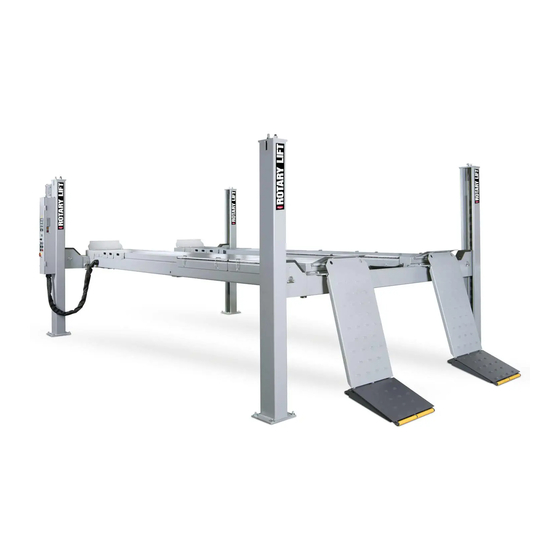
4 -Post Alignment Lift
SM65-55MB,SM35LT-51MB
SM65-51/55/60,MOT65-55/60
SM40-47-BMW ,MOT40NB-47
SM65-51/55/60
SM40-47-BMW
Installer: Please return this booklet to literature package and give to lift owner/operator.
© Rotary Lift, All rights reserved
SM40-47/51,SM40NB-47
SM40LT-47,SM55LT-51
SJ180101
SM55LT-51
SM40LT-47
OM-SM-3
Rev.B 01/01/2018
O
O
P
P
E
E
R
R
A
A
T
T
I
I
O
O
N
N
&
&
M
M
A
A
I
I
N
N
T
T
E
E
N
N
A
A
N
N
C
C
E
E
M
M
A
A
N
N
U
U
A
A
L
L
Advertisement
Table of Contents
Troubleshooting


Need help?
Do you have a question about the SM40-47 and is the answer not in the manual?
Questions and answers