Table of Contents
Advertisement
Quick Links
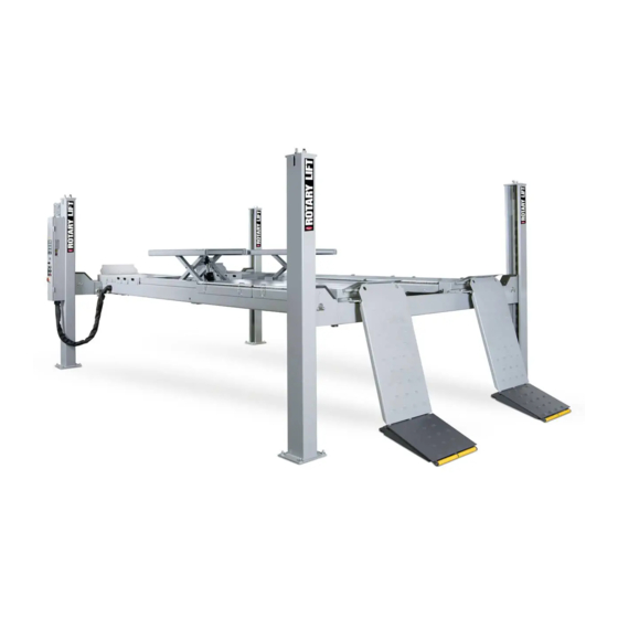
4 -Post Alignment Lift
SM65-51/55,SM55LT-51
Installer: Please return this booklet to literature package and give to lift owner/operator.
© Rotary Lift, All rights reserved
SJ140506
O
O
P
P
E
E
R
R
A
A
T
T
I
I
O
O
N
N
&
&
M
M
A
A
I
I
N
N
T
T
E
E
N
N
A
A
N
N
C
C
E
E
M
M
A
A
N
N
U
U
A
A
L
L
OM-SM-1
Rev.A 5/10/2014
Advertisement
Table of Contents
Troubleshooting

Related Manuals for Rotary SM65-51


Summary of Contents for Rotary SM65-51
- Page 1 4 -Post Alignment Lift SM65-51/55,SM55LT-51 & & Installer: Please return this booklet to literature package and give to lift owner/operator. OM-SM-1 SJ140506 Rev.A 5/10/2014 © Rotary Lift, All rights reserved...
- Page 3 BlitzRotary GmbH Hüfinger Str.55 78199 Bräunlingen, Deutschland This declaration relates solely to the machine as configured when launched onto the commercial market; partswhich have been added by the end user and/or modifications made following purchase remain unaffected. Unauthorised modifications or changes to this machine invalidate this Declaration. We hereby declare that the machine described below Product designation: 4-post lift Series/type designation: Load capacity 6500 kg SM65-51, SM65-55 Load capacity 5500/3500 kg SM55LT-51 Machine/serial number: ........... Year of manufacture: 20… complies with all key provisions of Machinery Directive 2006/42/EC. Furthermore, the machine complies with the provisions of the Electromagnetic Compatibility Directive 2004/108/EC and the Low Voltage Directive 2006/95/EC (safety standards have been met pursuant to Annex I, No. 1.5.1 of the Machinery Directive 2006/42/EC). Related harmonised standards:...
-
Page 4: Table Of Contents
Table of Contents 6.1 Manually lowering the lift when there is a height difference of > 50 mm ............24 ..............1. Introduction 6.2 Leveling the rolling jacks ..........25 1.1 About this operating manual ........4 6.3 Emergency manual function ........25 1.2 Warning and information symbols ......4 7. Technical data ..........27 1.3 Intended use ............5 8. Cleaning ............28 1.4 Incorrect use, incorrect behavior ......5 9. Maintenance and repair ........29 1.5 Internal accident, health and safety, and environme- ntal information ........ 5 9.1 Qualification of maintenance and repair staff ...29 2. Safety .............6 9.2 Maintenance and repair safety regulations ....29 2.1 Operators ..............6 9.3 Maintenance work ...........30 2.2 Basic safety requirements ........6 9.4 Approved hydraulic oils ..........33 2.3 Permitted axle loads and weight distribution ..7 9.5 Check, refill, change the hydraulic oil .......34... - Page 5 12.2 Connect the lift power supply .........46 13. Commissioning ..........48 13.1 Test the pneumatic and hydraulic system ....48 13.2 Test the safety mechanism ........48 13.3 Align the rolling jacks ..........49 13.4 Leveling the main lift..........49 14. Wheel alignment kit AK... (optional) ....50 14.1 Supplied parts ............50 14.2 Assembly ..............50 14.3 Adjustment work .............51 15. Disassembly ...........52 16. Disposal ............53 16.1 Environmental procedures for disposal ....53 16.2 Packaging ..............53 16.3 Oils, grease, and other chemical substances ..53 16.4 Metals / Electronic waste ........53 ANNEX • SM65-51/55, SM55LT-51: Pneumatic circuit diagram, wiring diagrams, hydraulic circuit diagram, spare parts lists • Maintenance schedule: Instructions for conducting visual inspections and function testing • Inspection log...
-
Page 6: Introduction
Risk of injury • The operating manual must be kept near the lift Potentially hazardous situation. and be easily accessible for all users. Non-compliance may lead to CAUTION • This operating manual provides information on minor or moderate injury. the post lifts SM65-51, SM65-55, SM55LT-51 variant with lifting table.. ATTENTION Damage to property • Make sure that you have read and understood Potentially hazardous situation. Chapter 2, Safety and also the operating Non-compliance may lead to instructions supplied with the machine. -
Page 7: Intended Use
not lowered into the lock position (latch bars). Intended use • The post lift may only be used: Activating the machine when safety equipment or • mechanisms are not in place (Example: locking In indoor areas for lifting unoccupied motor vehi- latches are not fitted). cles. • • For lifting vehicles with a max. load capacity of Driving onto the lift when the adjustable runways 6500 kg, 5500 kg , according to the lift variant. are incorrectly aligned. The permitted load capacity of the lifting table is • max. 3500 kg. • Lifting loads not listed in Chapter 1.3. • If the weight is distributed correctly. By default, Lifting vehicles containing hazardous goods. the load should be centered in the direction of •... -
Page 8: Safety
turer. Lift it for a short distance and check that 2. Safety the pick-up points are secure. Only then can the 2.1 Operators vehicle be moved to the required height. • Take steps against traffic in the area of the post The post lift may only be operated without super- lift. Do not park other vehicles in the danger zone. vision by persons who: • Do not load main lifts and lifting table beyond the • Are 18 years old and above. permitted capacity, comply with the permitted axle • Are familiar with the basic regulations on health & loads and load distribution in accordance with safety and accident prevention. Chapter 2.3. • Have been trained to handle and operate the post • When disassembling or fitting heavy vehicle lift. parts, watch out for dangerous shifts in the • Have proven their ability to do so to the company. weight balance, in particular when the vehicle • Have been expressly appointed in writing to ope- is supported by lifting table. Secure the vehicle rate the lift. beforehand. • Have read and understood the operating manual. • Always fully lower, switch off and secure main lifts and lifting tables to prevent unauthorized 2.2 Basic safety requirements use after completion of work (turn main switch to... -
Page 9: Permitted Axle Loads And Weight Distribution
Permitted axle loads and weight distribution Before lifting the vehicle, you must ensure that the weight distribution is correct. ↓ ↓ When the weight distribution is correct (default position in direction of motion) the main load is located at the front (e. g. engine). Risk of injury through toppling of the vehicle when incorrectly loaded. WARNING Comply with the permitted load capacity as in Fig. 1 and 2. Comply with the permitted weight distribution as in Fig. 1 and 2. Comply with the approved distances between pick-up points as in Fig. 3. Figure 1: SM55LT-51 (with lifting table) •... -
Page 10: Ban On Unauthorized Modifications Or Alterations
2.4 Ban on unauthorized modifications or Maintenance contractors, installa- alterations tion staff • Unauthorized modifications and alterations to the Maintenance, servicing and installation work post lift are not permitted for safety reasons. • may only be done by companies or specialists The operating permit shall also be deemed null authorized by the manufacturer. and void. • These people trained in the field of lifts are co- The Declaration of Conformity also becomes null and void. mpetent persons, who are trained for maintenance as well as repair work. Experts, competent persons A competent person is a person who has adequ- The post lift must be inspected after commiss-... -
Page 11: Safety Inspections By Competent Persons
Safety inspections by competent persons Safety inspections must be carried out to guar- antee the safety of lifts. Safety inspections should be carried out in the following cases: • Before initial operation, after initial installation. Use the form "Initial safety inspection before in- stallation“. • After initial operation at regular intervals, but at least once a year. Use the form "Regular Safety Inspection“. • After any design modification to parts of the lift. Use the form "Unscheduled Safety Inspection“. The initial safety inspection as well as the safety inspections must be carried out by a competent person. We recommend that you also perform maintenance in the course of the inspection. Unscheduled safety inspections and spec- ial maintenance work are required in the event of design modifications to the lift (fitting additional parts). The safety inspe-... -
Page 12: The 4-Post Lift
General workflow 3. The 4-Post Lift • After determining the vehicle data and aligning Overview of parts the runways, the vehicle is driven onto the main Figure 4: Example of a 4-post lift with lifting lift and secured against rolling. table (SM55LT-51) • 1. Standard lift column The vehicle is raised to the desired height with the main lift. 2. Lift column with control unit • 3. Automatic ramp chock With optional lifting table : 4. Cross beams If a lifting table is used, the manufacturer- approved pick-up points on the vehicle are 5. Power unit selected and the matching supports are placed 6. Control box underneath. After adjusting the selector on 7. Compressed air unit with lubricator(option) the control unit and checking that the weight distribution is correct, the vehicle is lifted by the 8. Base plate... -
Page 13: Work Area, Danger Zones
min 0.8m ② min 2m ③ min 0.8m ① min 0.8m Work area, danger zones Safety mechanisms See figures 6 ... 13 Safety mechanisms protect both Figure 5: Work area, danger zones people and lift. They must not be disabled! 1. Control area WARNING 2. Work area and danger zone 3. Vehicle overhang Post lift danger zones are protected by safety mechanisms. - Page 14 1. Buzzer Acoustic alarm. Sounds: • When lowering the main lift < 120 mm (foot protection). • When lowering the lifting table (hand and finger protection). • When troubleshooting (lifting/lowering using the override switch, for height equalizing or during emergency manual lowering). 2. Lockable main switch "ON“ setting: Post lift ready for use. "OFF“ setting: Post lift out of use. The mains voltage is still present inside the control box. Switching off (OFF) immediately stops any movement of the post lift (= emergency stop). 3. Locking latch on each lift column The locking mechanism consists of a latch bar and roller with cam shaft. Latch bar with 100 mm locking latch notches. If a fault occurs in the hydraulic system or if the cable breaks or becomes slack, the brake mechanism is activated. The cam is pressed against the latch bar through a powerful spring...
- Page 15 6. Pressure control valve The pressure control valve ( arrow) is factory set to ca. 210 bar. Prevents a sudden lowering of the lift in the eve- nt of a leak in the hydraulic hose (lowering speed = max. 1.5 x default speed). 7. Lowering valve (emergency release) and emergency manual valves • Pos. 6.1 Lowering valve for emergency release of the main lift (SM65 lift) . • Pos. 7: Emergency manual valve for main lift and rolling jack. Fitted differently acco- rding to variant. Before use check assignment to main lift and lifting table . During a power failure the valves close and stop any movement. 8. Broken cable and slack cable switch • Pos. 8.1: Broken cable switch: This switch is activated if the cable is broken. All movement of the post lift stops immediately. The control buttons will not function. Consult a competent person for repair.
- Page 16 9. Photo sensor for rolling jack runways: Guards against height differences of > 50 mm between the runways Stops the lowering or lifting process if the dif- ference in height between the two runways is greater than 50 mm.
-
Page 17: Control Unit
3.5 Control unit All movement of the lift stops immediately when you release a pressed button. Figure 14: Control unit in the lift column 1. Selector, only for SM55LT variant with lifting table: • Left setting: Main lift active • Right setting: Lifting table active 2. UP button For main lifts or lifting tables. Functions only if the button is pressed. Post lift /lifting table runways move up. 3. On/Off switch for optional lighting. 4. DOWN button • For main lifts or lifting tables . Functions only if the button is pressed. -
Page 18: Operation
4. Operation Emergency stop Risk of injury when lowering the 1. To perform an emergency stop, set the main swi- load onto objects below the lift tch to OFF ("OFF“setting). The main lift or the lift- or the vehicle. Vehicle may topple ing table stops immediately. DANGER over. Before lowering, you must remove all objects from underneath the lift. This applies in parti- Switch the machine on cular to chassis stands and auxiliary jacks. 1. Switch on the power supply with the main switch Always monitor the lift and vehicle carefully ("ON“setting). when lifting or lowering. 2. Check the operational status of the main lift and the lifting table. 3. Check the functionality of the control buttons. -
Page 19: Driving On
Driving on Lifting/lowering Risk of injury in the post lift zone. DANGER Do not put people at risk when the lift or lift- ing table moves. Always monitor the danger zones when lifting or lowering. No-one must stand in the traffic zone of the 1. If required, set the adjustable runways (Fig. 15, lift. Pos R) according to the width of the vehicle. To move them, loosen 2 runway bolts on each of the two cross beams, move the runways in parallel, Danger of crushing and shearing of then tighten the bolts again. limbs (foot, toe, finger etc.). Possib- le uncontrolledmovement when lo- 2. Drive the vehicle onto the runways centered on wering in the danger zone (below both sides (have someone guide you on). Make the runways, cross beams) or when... -
Page 20: Drive Off
Raising the lift Lowering the main lift or lifting table 1. Set the selector to the left (main lift). 1. Remove all objects in the lift and lifting table zone, in particular under the lift and lifting table. 2. Lift the main lift slightly with the UP button. 2. Set the selector to the desired position. 3. Check the steadiness and pick-up stability of the vehicle. 3. Using the Down button, steadily lower the lift or the lifting table until the automatic shut-off (120 4. Only start to lift smoothly and to the required mm) is activated. height if the vehicle is stable. To do so, first move the runways up for around Destruction of the hydraulic pump. 2 seconds to release them from the ratchets. Operating error, when the main lift Only then move the runways down until the au- is moved for long periods to its full tomatic shut-off is activated. The lowering proc- rise. -
Page 21: Problems, Causes, Actions
5. Problems, causes, actions The following lists contain information on pote- ntial problems,their causes, and actions to rect- ify the fault. Repairs to safety mechanisms on the lift If the lift is out of order for long periods, may richtungen only be carried out by carry out the following steps: authorized maintenance contractors 1. Lower the lift to the lowest position. - Page 22 Problem Possible cause Actions The motor is not running. • Mains fuse is faulty. Reset or change the mains fuse. The runways lower unevenly • An object is blocking the dow- Main lift during the lowering process → nward motion. The lowering 1. Move lift up slightly. Make sure Lift or lifting table runways tilted. process is aborted. that all cables are tensioned. • Load unevenly distributed. 2. Remove objects from under the Main lift • Settling function still active: lift. • Slack cable switch or broken main lift and lifting table partly 3. Carry out adjustments. To do so, cable switch activated. still in the lock position (Lock lower the lift completely. • Can lift when cable is slack. If bar/ratchets). 4. Check that lift is being cor-rectly cable is broken the whole lift • Slack or broken cable on one operated. is locked. of the lift columns. 5. If this cannot be done: • Lowering locked.
-
Page 23: Troubleshooting By Authorized Maintenance Contractors
Lift button does not work. • Hydraulic oil level too low. 1. Refill hydraulics up to gauge Main lift or lifting table: mark ( →Chapter 9.4). Runways do not move up. 2. Check with dipstick. Attention: Using rapeseed based oil destroys the seal.Use only biodegradable oils(HEES-oils based on synthetic esters). The water content of the oil may not exceed 2 %. Do not mix bio-oils with mineral oils. Runways do not lift with a load. • The lift is overloaded. Rated 1. Check vehicle weight. They do however rise without a load capacity ex-ceeded, If necessary reposition the vehicle load. maybe on one runway. ( → Chapter 2.3. rated weight • Hydraulic pressure incorrectly distribution). set on pressure control valve. 2. Correct setting on pressure control valve. Power failure on main lift which • No mains supply. Can only be lowered with manual is locked in the latch bars. pump and optional hydraulic power unit. Troubleshooting by authorized maintenance contractors Problem Possible cause... - Page 24 The motor is not running. • Incorrect supply voltage to the Depending on cause: motor. • Supply the correct voltage to the • Wiring loose. motor. • Faulty motor. • Check all wiring connections and • Faulty limit switch. repair or insulate if necessary. • Test function of the Up switch. Replace if necessary. • Check function of overhead limit switch. Replace if necessary. • Change hydraulic power unit for motor. Up button does not work. • Lowering valve is open. Depending on cause: Runways do not move up(main • Pump is sucking air. • Clean or replace lowering valve. lift or lifting table). • Suction pipe disconnected • Tighten fittings on suction pipe. from pump. • Replace suction pipe. Runways do not lift with a • Insufficient voltage supplied Depending on cause: load. Runways rise however to motor hydraulic power unit. • Supply the correct voltage to the without a load. • Lowering valve is dirty. motor.
- Page 25 Hydraulic oil leaking from the • Air has mixed with the oil or Depending on cause: filler/breather cap. is being sucked in. • Change oil ( → Chapter 9.4). • Oil return line is loose. • Tighten fittings on suction pipe. • Hydraulic hose is damaged. • Attach return line. • Replace hydraulic hoses. Runways lift unevenly • Cables are out of adjustment Depending on cause: (Height difference in runways). • Lift not leveled. • Correct the cable tension • Floor is uneven. (→ Chapter 11.11 and 13.4). • Reset and accurately level the lift. • Place spacers/shims underneath ( Chapter 13. Commissioning). Anchor is loose. • Assembly fault, Depending on cause: • Repair the lift. for example drill holes are too big or load capacity of • Re-install concrete floor is inadequate.
-
Page 26: Authorized Lowering
6. Authorized lowering Only by authorized competent persons Risk of injury in the case of incor- rect behavior. Only authorized competent persons may lower lifts as described below. WARNING Cordon off the danger zone, prevent access by all persons. Constantly monitor the danger zones when lifting or lowering. No-one may remain in the lift traffic zone. Only qualified electricians may carry out work on the electrics. Figure 16 1. Electronic alignment control button: Functions only when the photosensor is disconnected 2. Lifting table leveling button Manually lowering the lift when there is a height difference of >... -
Page 27: Leveling The Rolling Jacks
6.2 Leveling the lifting table Emergency manual function Even if the post lift fails totally, the vehicle can be lowered, for example by disconnecting the power Risk of injury due to height differe- supply. nce in the runways when the lift is The main lift tables can be lowered from one loaded.Vehicle may topple over. DANGER locking latch to the next, albeit step by step. Adjust the height of the runways slightly. Example: Lowering the main lift: Avoid large differences in height between the runways. - Page 28 3. Remove the valve from the threaded rod and screw on the metal cap completely (Emergency Manual = active). 4. Remove the plastic cap from the lowering valve. 5. Turn the brass screw to the left to lower the main lift to the next lock position. 6. Repeat the process until the main lift has been lowered completely to the floor. 7. Turn the brass screw to the right as far as it will go to close the pressure control valve, otherwise the lifting function will not work. 8. Screw on the plastic cap. 9.Refit the emergency manual valve. Make sure that the metal cap is screwed on completely, otherwise the lifting function will not work.
-
Page 29: Technical Data
7. Technical data SM65-51 SM55LT-51 SM65-55 Load capacity 6500 kg 5500kg Main Lift Lifting table 3500kg 1750mm 1750mm Main lift Stroke lift 1900 mm 1900mm Lifting table(on 300/ 400mm lock position) C Overall length 5365 mm 5365 mm with drive-on 5765 mm ramps D Overall width 3405 mm 3405 mm Drive-on height of... -
Page 30: Cleaning
8. Cleaning • Only clean the lift when not loaded (without vehicle). • Clean main lift, lifting table and all work areas daily. In doing so, always keep all post lift components clean. If the lift is in a particularly dirty environ- ment, clean accordingly more frequently. • Do not use abrasive cleaning materials on lift parts and covers. Use lint-free cloth. • Do not use compressors or high pressure cleaners for cleaning work. • Always consult a maintenance contractor if you identify a hazard. • Prior to maintenance make sure that fittings and fixtures are free of oil, lubricants, and cleaning materials. • Cables (running steel cable) must be regularly lubricated with a suitable lubricant, from example from Duotac, CRC or Mobil (Mobilarma 798). -
Page 31: Maintenance And Repair
• 9. Maintenance and repair Prevent environmental hazards: • Mineral-oil-based hydraulic oil is combustible Inadequate maintenance and repair and a water pollutant. It must only be used in work may cause serious injury and conjunction with the relevant safety data she- also lead to damage to property. A et and if all specified measures contained safety risk as well as a risk of fatal DANGER therein are implemented. injury exists during operation. •... -
Page 32: Maintenance Work
9.3 Maintenance work Daily inspection 1. Check whether the automatic wheel chocks, drive-on ramps, or the chocks and drive-on Potential crushing and shearing hazard to limbs caused by unc- chocks are damaged or show signs of wear. ontrolled lowering motion. Replace damaged or worn parts. WARNING 2. Check the function of the locking latches on the In particularly dirty environments, maintain main lift (visual inspection). To do so, lock the the post lifts accordingly more frequently. main lift in the locking latches then raise and Only perform maintenance on unloaded lifts, tension the cable. i.e. without vehicle. 3. Check horizontal alignment of runways. Before maintenance work lower the main lift Runways must be horizontally aligned and at the completely or lower and latch into the lock same height. If not, correct the alignment ( → (locking latches). Chapter 13. Commissioning). Turn the main switch to OFF ("OFF“ setting) 4. Check the cables and cable sheaves for wear and lock with a padlock. - Page 33 5. Test the buzzer (→ Chapter 3.4, Pos. 1). A buzzer must also sound when lowering in the foot protection zone. If the buzzer is faulty the post lift must not be operated.
- Page 34 Monthly maintenance 1. Turn the main switch to OFF ("OFF“ setting) and lock with a padlock. 2. Check whether the runways and lifting tables are horizontally aligned during lifting and lowering and move up and down. Re-adjust stretched cables ( → Chapter 13. Commissioning). 3. Check whether screw fittings have come loose. This applies in particular to screw fittings between drive-on surfaces and cross beams. 4. Check the hydraulic oil level (Hydraulic tank). If necessary, refill with approved hydraulic oil (→ Chapter 9.4) ("max“ mark. Empty tank capacity 11 liters). 5. Inspect the tank cover of the hydraulic tank. The vent cap must be clean so that no vacuum can form. Clean if necessary. 6. Check hydraulic component seals (visual in- spection). 7. Turn main switch to ON ("ON“ setting). 8. Check that control buttons and switches function properly. 9. Carry out a function test with and without load. 10.Complete a maintenance report (→ Annex). Six month maintenance 1. Raise lift and lifting table. 2. Turn main switch to OFF ("OFF“ setting) and lock with a padlock.
-
Page 35: Approved Hydraulic Oils
Annual maintenance 9.4 Approved hydraulic oils Important information 1. Turn the main switch off (Position "OFF“) and lock • with padlock. Only use hydraulic oils in accordance with DIN 51524 for the hydraulic system. • 2. Lubricate cross beam cable sheaves with grease Only use biodegradable oils (Consistency classification II). (HEES-based on synthetic esters). • Use PTFE seals or foam elastomers if the water 3. Check Hydraulic cylinder and Hydraulic hoses for content is high. leaks (visual inspection). 4. Inspect electrical cables for damage (visual ATTENTION Seals may be destroyed if the inspection). incorrect hydraulic oil is used. 5. Turn the main switch on again (Position "ON“). Do not use rapeseed based oils. The water content of the hydraulic oil must 6. Check that control buttons and switches function not exceed 2%. -
Page 36: Check, Refill, Change The Hydraulic Oil
9.5 Check, refill, change the hydraulic Risk to people and the environment from toxic substances when filling the hydraulic oil tank. WARNING Avoid contact with and inhalation of hydraulic oil. Wear protective clothing (protective goggles, protective gloves). Provide suitable oil drain pans and oil abso- rbents. Ensure that no hydraulic oils, lubricants, or cleaning materials contaminate the soil or leak into the drainage system. Comply with local regulations for handling water pollutants, for example for absorbing leaking fluids or fluids from oil separators. Hydraulic oil is highly inflammable, combu- stible. 1. Check hydraulic oil level on the hydraulic oil tank. The oil level must not exceed the minimum value ("min“). -
Page 37: Repair Work (Repairs)
Worn ratchets 9.6 Repair work (Repairs) 1. Proceed as above under Change cylinders, Pos. 1 to 4. If repairs are carried out incorrectly, they may cause serious injury and 2. To safeguard against unforeseen lowering, also also lead to damage to property. A place suitable supports under the post lift at the safety risk as well as a risk of fatal lift columns. - Page 38 Replace cables/cable sheaves • Damaged cables must be replaced promptly. • If cables / cable sheaves are damaged, inform maintenance contractors and customer service immediately. • Always replace all cables together as a set. • If the cable is too slack → Chapter 13. Commissioning. • Replace cables as per the manufacturers training.
-
Page 39: Transport, Storage
1. Lift column with control unit 2. Drive-on ramps 3. Cross beams 4. Lift columns 5. Tracks(runways 6. Control box 10. Transport, Storage ATTENTION Lift components may be damaged if offloaded incorrectly. Crushing and shearing hazard for limbs when unloading. Do not damage plates on the underside of Caused by collapsing or slipping of the lift when lifting. DANGER the load. Several parts are inserted into the compon- ents, for example into the runways. Offload Only unload the packing unit and transport these carefully to prevent damage. -
Page 40: Transport
10.2 Offloading 10.3 Storage 1. Inspect the shipment for any shipping or transport Lift components must always be stored in a dry damage. Immediately report any damage to your place (no corrosion protection). supervisor and to the transport firm. Recommended Storage Conditions 2. If there is any transport damage, contact the • transport firm. Ambient temperature: -5 ... +50 • 3. Transport the packing unit to the installation site. Relative humidity, 30 % ... 95 % with condensation, at 20 °C This must conform to the approved environmental conditions ( → Chapter 7. Technical data). The manufacturer provides no warranty for 4. Unfasten the transport locks for the large parts on corrosion damage caused by incorrect the front of the packing unit. storage. 5. Offload the runways and cross beams and set down carefully. Recommended: Raise the runways and cross beams slightly, for example set down onto stable wood beams. This will also enable... -
Page 41: Assembly
11. Assembly 11.2 Quick assembly instructions The lift components are already preasse- Incorrect installation work may mbled ex works. When assembling these lead to serious injury and material must simply be joined together, electric, damage. A safety risk as well as a pneumatic, and hydraulic lines must be risk of fatal injury exists during DANGER properly connected. operation. Follow the instructions below carefully. 1. Determine the installation site of the post lift. Only customer service staff authorized by the Check the foundation. If necessary, reinforce the foundations at the point where the lift columns will manufacturer may assemble and commission... -
Page 42: Site Specifications
• 11.3 Site specifications Runways must be fitted straight and level. Height • tolerance ± 5 mm, max. difference between di- The post lift may only be installed above ground agonals 6 mm. and indoors. • Refer to the building plans when selecting a site. • Tighter tolerances are defined for the optional When anchoring to the floor, take into account wheel alignment kit, according to any pipes, cables, and supply lines lying there. • manufacturer’s specifications. Ensure that the load capacity of the foundation is • adequate. • Factor in sufficient space for the approach and Support surface for lift columns: drive-off. Take drive-on ramps into account. Reinforced concrete, concrete quality • C20/C25 • Take note of the maximum bearing pressure Floor load capacity for each lift column (34 x 23 under the lift column. Take into account the cm): Min. 2000 kg. -
Page 43: Prepare The Runways
11.5 Prepare the runways 11.6 Prepare the cross beams Cables and sheaves are prefitted in the run- 1. Position both cross beams under the runway ways and secured by transport locks. beams at the ends of the runways. Make sure that markings A to D match up. The runways can be fitted with the approach area on the left or right. 2. Pull out the cable sheaves on the right and left of the two cross beams. Always attach the fixed runway to the lift col- 3. On each axle (1), disassemble the screw (2) and the distance sleeve(4) and take out the umn with the control unit. cable sheave (3). 1. Set down both runways onto stable wood beams at the installation site with a distance of around. 0.9 m between them. Use the A to D markings. Label "A“of the fixed runway to the power supply. 2. Pull out the cables and pneumatic lines on the front ends of the runways. These must be rolled in under the runways and secured).(see fig 24 ) 3. Insert the cables into the cable sheaves of the runways. Make sure they are correctly positioned in the cable sheaves. 4. Lubricate the cable sheave grooves on both front ends of the fixed runways (for grease see Chapter 9.4). 5. Insert the fitting (metal guard) for flexible hoses from inside and outside into the fixed runway and 5. Route the cable assembly with the electrical, tighten. -
Page 44: Set Up The Cables
3. Fit the two runways to the cross beams with the 11.7 Set up the cables supplied M10*30 bolts ( see Fig. 29). 1. Pull out the 4 cables according to the cable Tightening torque table in Nm where µ = 0,12 diagram through the cross beam and route them out of the cross beams. They must protrude from the cross beam by about the same distance. Thread Property class 10.9 12.9 M 4 1.3 4.6 ATTENTION Malfunction if cables are crossed M 5 2.7 5.9 8.6 or slack. M 6 4.7 10.1 14.9 17.4 M 8 11.3 24.6 36.1 42.2 Ensure that the cables are pulled tight within M 10 22.9 48... -
Page 45: Attach The Latch Bars And Cables
Slide on the lift column onto the two cross beam 7. Fit the 4 lift columns onto the shims with guides leaving a gap of 1 mm and align precisely approved nuts and bolt locking devices. Select with a spirit level . the tightening torque according to the bolt manufacturer’s specifications. Also consider the 5. Mark the 4 anchoring holes on the floor and for on-site conditions. each lift column and drill (Ø 16 mm, 130 mm deep). Clean the drill holes. Risk of fatal injury if lift columns 6. Insert all 16 anchor bolts into the holes. Use a are not secured properly. Lift or rubber mallet if necessary. load could topple or collapse. DANGER Comply with the specified torque on each Approved anchor bolts bolt. If this is not possible, repair the floor acc- Manufacturer Type Thread ording to specifications ( → Chapter 11.3), MKT... -
Page 46: Attach The Flexible Hose
5. Lock at the top using the M20 lock nut. 11.12 Assemble the hydraulics module • 6. Screw the threaded sleeve (4) for the cable (5) Only qualified staff with specialist knowledge and into the top plate from below so that the cable is experience of hydraulics may work on hydraulic lightly tensioned. Do not yet secure the cable. equipment. • 7. Secure the threaded sleeve at the top with an Always follow the safety regulations in the hy- M22 lock nut(6). draulic power unit instructions in the annex to this manual. The hydraulic power unit with motor and tank is 11.11 Attach the flexible hose supplied separately and is assembled as follows: 1. Screw the 4 threaded pins with rubber pads (2) into the lift columns. Risk of injury from heavy hydraulic power units. CAUTION If possible, assemble the complete unit in pairs. 2. Attach the complete hydraulic power unit to the 4 threaded pins with the mounting plate (3), fit spacers and secure with self-locking nuts. -
Page 47: Electrical Connections
4. Open the tank cap and fill the tank with 11 liters 3. Connect the supply lines (Fig. 34/35, arrow) to of hydraulic oil. For approved hydraulic oil types, the hydraulic block. see Chapter 9.4. • SM55LT with 2 emergency manual valves one fitting for main lift one fitting for lifting tables. 12.Electrical connections • SM65 with 1 emergency manual valve Risk of electrocution. Faulty elect- rical work may lead to critical injury and also to damage to property. DANGER Always follow the instructions below. Proper installation and commissioning must be documented in the inspection logbook. Use the form "Initial safety inspection before installation“. 12.1 Safety instructions for connecting power cables •... -
Page 48: Connect The Lift Power Supply
• 12.2 Connect the lift power supply All main switches must be switched to “O” when working on the electrics of this machine. The mains power supply must be disconnected at the fuse box (disconnect the mains fuse) and isolated to prevent accidental reconnection. A clearly visible warning sign must be attached accordingly. 1. Disconnect the mains fuse and attach a sign warning against reconnection. 2. Connect the cable assembly terminals to the corresponding connectors. The connectors are coded so that only matching terminals can be connected. Connect 4 terminals to main lift, one terminal for lifting table. 3. Feed the hydraulic supply lines and power cables from below through the lower knock-out in the control box and connect to the hydraulic power unit (→ Annex, Power unit operating instructions, hydraulics diagram). 4. Check the voltage, current and power ratings on the information plate. Make sure the approved structural conditions for connecting the power cables are in place. 5. Remove the motor connection box cover and route a 5-core power cable through the cable gland into the connection box accordingly. - Page 49 7. Establish a mains connection (→ Fig. 37 and 38) • Standard configuration with 400 V connection (3+N+PE): W2 – U2 – V2 bridge. • Alternatively 3 x 230 V- connection: Change the wiring on the transformer ( → arrow, Fig.39) to 230 V. Remove the six M5 nuts in the motor connection box, bridge U1–W2, V1–U2, W1–V2 according to the diagram and tighten the nuts again. 8. Make sure that the equipment is properly earthed. Do not connect the earth conductor to gas, water, or telecommunications installations. 9. Attach the motor connection box cover. 10.Check the direction of rotation of the motor (see also direction of the arrow on the motor). To do so, close the control box, connect the mains fuse, turn the main switch to "ON“ and push the Up button. Reverse the polarity if the direction of rotation is incorrect.
-
Page 50: Commissioning
5. Raise the lifting tables with the Up button. 13. Commissioning 6. Mask the photosensors between the runways. 13.1 Test the pneumatic and hydraulic system 7. Push the Down button (whilst turning the selector to main lift and rolling jack respectively). The pneumatic connections must be establis- hed on-site by the user. The Down function must be deactivated. Neither the main lift nor the rolling jacks may be lowered. 1. Only connect the pneumatic line to the pneumatic female coupler. 8. Remove the adhesive strips on the photosensor. 2. Set the air pressure on the manometer to 6 .. 8 bar. Test the "Slack cable” function 9. Lock the main lift to the latch bars with the Lock 3. Set the main switch to ON. button. Press the button until the cables are completely slack. 4. Move the unloaded lift to full rise and the bottom position several times using the Up and Down 10.Push the Electronic Alignment Control button... -
Page 51: Align The Rolling Jacks
13.3 Align the lifting tables Fine adjustments to the latch bars and cables 1. Ensure that no vehicle is on the lift or the lifting 1. Ensure that no vehicle is on the lift or the lifting tables (lift is unloaded). table (lift is unloaded). 2. Test the alignment function as in Chapter 6. 2. Raise the main lift by around 1 m with the Up button. 13.4 Leveling the main lift 3. Lock the main lift into the latch bars with the Lock Use a spirit level, an automatic level and marker button. Make sure that it latches into all 4 latch discs on the driving surfaces for adjustment bars. work (positions A and B), → Figure 42. 4. Switch main switch to OFF. Make fine adjustments to lift columns 3. Ensure that no vehicles are on the lift or the lifting tables (lift unloaded). 4. Using the spirit level, check the vertical alignment of the lift columns. If skewed, carry out the following steps. -
Page 52: Wheel Alignment Kit Ak
13.Tension the threaded sleeves (2) of the cables 14.Wheel alignment kit AK... (3) on the 4 lift columns slightly. (optional) 14.Turn the main switch to ON and lower the main 14.1 Supplied parts lift to the floor. Wheel alignment Kit for post lift types SM65, The lifting tables are already height adjusted SM55LT,consisting of • ex works and do not need to be leveled. 1050mm slip plate • Fixed /end filler plate • • Moveable filler plate Optional: Turning radius gauge for the relevant wheel alignment system (noly can sit for 450mm,380mm width turn table) 14.2 Assembly These post lifts can be combined with wheel alignment systems from different manufacturers. The post lifts must be converted for use. Thus, on each runway the base plate at the front and back must be replaced by filler plates and slip plates from the wheel alignment kit. On each side: 1. Remove the lifting table ramp (only for SM55LT). 2. Put the slip plate cover the runway. Adjust the cables 1. Drive a vehicle with a total weight of 2000 kg centered onto the main lift. Make sure that the vehicle is also centered laterally on both run-... -
Page 53: Adjustment Work
5. Remove the base plate on the drive-off side To do this, place a spirit level onto the surface (automatic ramp chock end). of the runway first lengthwise and then onto the cross beam. 6. Put the end fixed filler plate in such a way that all bolts protrude from the underside of the runway. 3. Lock the lift into the latch bar. Depending on the wheel base, put the moveable filler plate before or behind the turning radius 4. Adjust the cables with the nuts on the cable end. gauge. Then lock the nuts. Make sure that all latches are at the same height. bolts&washer Adjust the runways according to the requirements of the vehicle manufacturer. To do so, the following measuring equipment is required: • • Automatic level Measuring stand with scale in mm. 5. Drive the vehicle onto the lift so that the front wheels stand on the turning radius gauge and the rear wheels on the slip plate. The vehicle must come to a halt virtually centered on the lift in the direction of motion. 6. Loosen the lock pins on the turning radius gauge and slip plates. Make sure that the vehicle can now slip easily on the plates and that no tension exists so that the adjustment work can be carried bolts&washer out precisely. -
Page 54: Disassembly
11. This concludes the initial adjustment work (initial 15. Disassembly measurement). • Disassembly work may only be carried out by 12.Then lift the runways when loaded with the authorized qualified staff. vehicle to the desired working height and lower • into the four latch bars with the Lock button. Only qualified electricians may work on the elec- trics. 13.Make a note of the 4 measurements of the wheel • footprint at this height. Only trained persons with specialist knowledge of hydraulics/pneumatics may work on the hydraulic 14.Adjust the latch bars. To do so, loosen the jam or pneumatic equipment. nuts on the threaded rods and raise or lower the latch bar with the adjusting nut. Make sure that all 1. To carry out disassembly work, switch off the 4 wheel footprints have the same height reading. equipment at the main switch (position OFF). 15. Then tighten the jam nuts of the threaded rods 2. Disconnect the mains fuse and attach a warning again. sign to prevent reconnection. 16. Archive the measurement report with the upda- 3. Switch off the compressor unit (compressor unit ted measurements. manometer to 0 bar) and disconnect the line to the post lift. -
Page 55: Disposal
16. Disposal 16.1 Environmental procedures for disposal • Prevent environmental hazards. • Avoid contact with or inhalation of toxic sub- stances such as hydraulic fluid. • Oils and lubricants are water pollutants under the terms of the Water Management Act WGH. Always dispose of these in an environmentally friendly manner in compliance with the regula- tions which apply in your country • Hydraulic oil-based on mineral oil is a water pol- lutant and is combustible. Refer to the relevant safety data sheet for disposal. • Provide suitable oil drain pans and oil absorbents to drain the oil. • Ensure that no hydraulic oil, lubricants, or clean- ing materials contaminate the soil or wash away into the drainage system. 16.2 Packaging Do not dispose of with domestic waste! The packaging contains some recyclable material which must not disposed of with domestic waste. - Page 58 Tel +49.771.9233.0 USA: +1.812.273.1622 (Headquarter) Latin America/Caribbean: +1.812.273.1622 BlitzRotary GmbH Fax +49.771.9233.99 Canada: +1.905.812.9920 Middle East/Northern Africa: +49.771.9233.0 Hüfinger Straße 55 info@blitzrotary.com United Kingdom: +44.178.747.7711 Southern Africa: 1.812.273.1622 D-78199 Bräunlingen AustralAsia: +60.3.7660.0285 Brazil:+55.11.4534.1995 www.blitzrotary.com...
Need help?
Do you have a question about the SM65-51 and is the answer not in the manual?
Questions and answers