
Related Manuals for Welbilt KOOLAIRE K0170 Series


Summary of Contents for Welbilt KOOLAIRE K0170 Series
- Page 1 Koolaire Ice Machines Course ID #ICE2114, Koolaire Ice Machine Training (4 Hour duration) © Welbilt, Inc.
- Page 2 – Interior Cleaning and Sanitizing ─ Disassembly / Removal – Sequence of Operation – Troubleshooting • Modular – Product Introduction & Overview – Installation – Interior Cleaning and Sanitizing ─ Disassembly / Removal – Sequence of Operation – Troubleshooting © Welbilt, Inc.
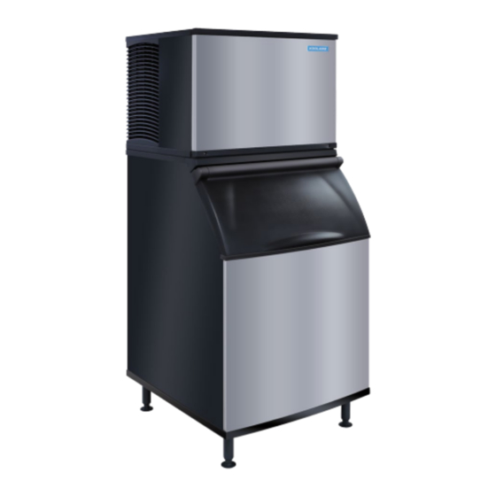
- Page 3 Overview Koolaire UnderCounter Ice Machines © Welbilt, Inc. © Welbilt, Inc.
-
Page 4: Component Identification
Koolaire UnderCounter Ice Machines : Overview Component Identification Ice making and Bin compartment Data Plate Removable Front Cover Washable Air Filter 2ea Front Cover Screws © Welbilt, Inc. -
Page 5: Control Box
Koolaire UnderCounter Ice Machines : Overview Component Identification Data Plate Compressor Compartment Service Valves Condenser High Pressure Cut Out Control Box Fan Cycling Switch Hot Gas Valve Ice/Off/Clean Switch © Welbilt, Inc. -
Page 6: Ice Thickness Probe
Koolaire UnderCounter Ice Machines : Overview Component Identification Evaporator Ice Thickness Probe Damper Door Water Trough Overflow Drain © Welbilt, Inc. - Page 7 Koolaire UnderCounter Ice Machines : Overview Component Identification: (Water Pump Cover Removed) Discharge Thickness Hose Probe Water Pump Bin Switch Magnet Siphon Cap & Damper Overflow Door Tube Water Float Valve Trough © Welbilt, Inc.
- Page 8 REFRIG. CHARGE 14OZ 0.397KG DESIGN PRESSURE HIGH SIDE P.S.I.G 34 BAR P.S.I.G. DESIGN PRESSURE LOW SIDE P.S.I.G 17 BAR LEAKAGE TESTED Manitowoc (China) Foodservice Co., Ltd. DPMCRE1 MADE IN CHINA Hangzhou, China Behind front cover Right Side © Welbilt, Inc.
- Page 9 261 – 208-230/60/1 REFRIGERANT TYPE 251 – 230/50/1 T – R410A 263 – 208-230/60/3 F – R404A 463 – 460/60/3 P – R290A Refrigerant type identifier has been added to model numbers . Company Confidential (Employee information only) © Welbilt, Inc.
- Page 10 Koolaire UnderCounter Ice Machines : Overview Review • Overview o Component Identification −Compressor Compartment −Evaporator Compartment o Model Number © Welbilt, Inc.
-
Page 11: Installation
Installation Koolaire UnderCounter © Welbilt, Inc. © Welbilt, Inc. - Page 12 UnderCounter Installation: Installation, Operation and Maintenance Manual © Welbilt, Inc.
- Page 13 5" (127 mm)* Back 5" (127 mm)* 5" (127 mm* There is no minimum clearance requirement for the top or left and right sides of the ice machine. The listed values are recommended for efficient operation and servicing only. © Welbilt, Inc.
-
Page 14: Ice Machine Heat Of Rejection
Ice Machine Heat of Rejection Heat of Rejection* Series Ice Machine Air Conditioning** Peak K0170 2200 2600 K0270 3800 6000 © Welbilt, Inc. -
Page 15: Leveling The Ice Machine
1. Screw the leveling legs onto the bottom of the ice machine. 2. Screw the foot of each leg in as far as possible 3. Move into position 4. Level the ice machine to ensure that the siphon system functions correctly. © Welbilt, Inc. -
Page 16: Electrical Requirements
Local, state or national requirements will supersede our minimum requirements. Refer to the Data plate to verify electrical data. Ice Machine Max Fuse / Circuit Breaker Total Amps K0170 15 amp K0270 15 amp 10.7 © Welbilt, Inc. -
Page 17: Water Service / Drains
3/8" (.95 cm) min inside diameter Water Inlet Thread 90°F (32°C) Max. 80 psi (552 kPa) Max. 1/2" (1.27 cm) Female Pipe Bin Drain 1/2" (1.27 cm) min inside diameter Thread Ice Making Water Inlet Bin Drain © Welbilt, Inc. - Page 18 Koolaire UnderCounter Ice Machines : Overview Review • Location of Ice Machine • Clearance Requirements • Heat of Rejection • Leveling • Electrical Requirements • Water Service / Drains © Welbilt, Inc.
-
Page 19: Cleaning And Sanitizing
Cleaning & Sanitizing Koolaire UnderCounter Ice Machines © Welbilt, Inc. © Welbilt, Inc. -
Page 20: Exterior Cleaning
• Sponge any dust and dirt off the outside of the ice machine with mild soap and water. Wipe dry with a clean, soft cloth. • A commercial grade stainless steel cleaner/polish can be used as necessary. © Welbilt, Inc. -
Page 21: Air Filter Cleaning
• This helps keep the condenser clean. • Remove by sliding out the left side of the front cover. • Clean the filter with a mild soap and water solution. © Welbilt, Inc. - Page 22 Interior Cleaning / Sanitizing • Cleaner for Lime or Mineral Build-up • Sanitizer for Disinfecting KOOLAIRE Approved: Use only Manitowoc approved ice machine • Manitowoc Ice Cleaner = 000005163 cleaner and sanitizer. • Manitowoc Ice Sanitizer = 000005165 © Welbilt, Inc.
- Page 23 Step 1: Set the toggle switch to the OFF position after ice falls from the evaporator at the end of a Harvest cycle. Or, set the switch to the OFF position and allow the ice to melt off of the evaporator No ice on the evaporator. © Welbilt, Inc.
- Page 24 UnderCounter: Cleaning & Sanitizing Interior Cleaning / Sanitizing Step 2: Remove all ice from the bin No ice in the Bin. © Welbilt, Inc.
- Page 25 UnderCounter: Cleaning & Sanitizing Interior Cleaning / Sanitizing Step 3: To start a cleaning cycle, move the toggle switch to the WASH position. © Welbilt, Inc.
- Page 26 UnderCounter: Cleaning & Sanitizing Interior Cleaning / Sanitizing Step 4: Add the proper amount of Manitowoc Ice Machine Cleaner to the water Trough. © Welbilt, Inc.
- Page 27 Condenser Time Compressor Pump Solenoid Coil Fan Motor 1. Clean or Sanitize 10 Minutes Rinse Sequence: 45 Seconds 2. Water Purge 3. Rinse 90 Seconds Until Toggle 4. Stop Switch is moved *Total time approximately 22 minutes. © Welbilt, Inc.
-
Page 28: Step 6: Remove Parts For Cleaning
UnderCounter: Cleaning & Sanitizing Interior Cleaning / Sanitizing Step 6: Remove parts for cleaning. © Welbilt, Inc. - Page 29 UnderCounter: Cleaning & Sanitizing Interior Cleaning / Sanitizing Step 6: Remove parts for cleaning. © Welbilt, Inc.
- Page 30 UnderCounter: Cleaning & Sanitizing Removable parts for Cleaning / Sanitizing INNER TUBE UPPER THUMBSCREW INNER TUBE KEYWAY LOWER THUMBSCREWS © Welbilt, Inc.
- Page 31 UnderCounter: Cleaning & Sanitizing Interior Cleaning / Sanitizing Step 7: Mix a solution of cleaner and warm water. Solution Type Water Mixed with Cleaner 1 gal. (4L) 16oz (500 ml) cleaner *NOTE: Never mix cleaner and sanitizer together. © Welbilt, Inc.
- Page 32 Step 9: Use ½ of the solution to clean all food zone surfaces of the ice machine and bin. After Cleaning: Rinse all areas thoroughly with clean water. NOTE: When Sanitizing, Do not rinse the sanitized areas. © Welbilt, Inc.
- Page 33 Koolaire UnderCounter Ice Machines : Cleaning & Sanitizing Review • Exterior Cleaning • Cleaning / Sanitizing procedure • Removable parts for cleaning © Welbilt, Inc.
-
Page 34: Sequence Of Operation
Sequence of Operation Koolaire UnderCounter Ice Machines © Welbilt, Inc. © Welbilt, Inc. - Page 35 (AIR COOLED ONLY) CUTOUT (12) START FAN CYCLE CONTROL CAPACITOR CONTACTOR R 11 OVERLOAD CONTACTS PROTECTOR (15) (13) COMPRESSOR START NOTE: Control board does what it is programed to do and what input devices tell it to do. © Welbilt, Inc.
- Page 36 HIGH PRES. (AIR COOLED ONLY) CUTOUT (12) START FAN CYCLE CONTROL CAPACITOR CONTACTOR R 11 OVERLOAD CONTACTS PROTECTOR (15) (13) COMPRESSOR START NOTE: Toggle switch is a single pole double throw rocker switch- making circuits to ground. © Welbilt, Inc.
- Page 37 (AIR COOLED ONLY) CUTOUT (12) START FAN CYCLE CONTROL CAPACITOR CONTACTOR R 11 OVERLOAD CONTACTS PROTECTOR (15) (13) NOTE: Bin switch is a magnetic proximity switch. COMPRESSOR START Open damper = Open Switch / Closed Damper = Closed Switch © Welbilt, Inc.
- Page 38 HIGH PRES. (AIR COOLED ONLY) CUTOUT (12) START NOTE: ITP senses a change of resistance through a capacitive FAN CYCLE CONTROL CAPACITOR CONTACTOR R 11 OVERLOAD discharge when water is in contact. CONTACTS PROTECTOR (15) (13) COMPRESSOR START © Welbilt, Inc.
-
Page 39: Control System
FUSE WATER PUMP TRANS. High Pressure (14) FAN MOTOR Cut out HIGH PRES. (AIR COOLED ONLY) Fan Cycling CUTOUT (12) pressure START FAN CYCLE CONTROL CAPACITOR CONTACTOR R 11 OVERLOAD CONTACTS switch PROTECTOR (15) (13) COMPRESSOR START © Welbilt, Inc. - Page 40 Koolaire UnderCounter Ice Machines : Sequence of Operation Initial Start: Push Toggle Switch to start making ice! • The toggle switch must be in the Ice/On Position • Bin Switch must be closed / not sensing ice before the ice machine will start. © Welbilt, Inc.
- Page 41 • Hot Gas Solenoid Valve HOT GAS SOLENOID FUSE WATER PUMP TRANS. (14) FAN MOTOR HIGH PRES. (AIR COOLED ONLY) CUTOUT (12) START FAN CYCLE CONTROL CAPACITOR CONTACTOR R 11 OVERLOAD CONTACTS PROTECTOR (15) (13) COMPRESSOR START © Welbilt, Inc.
- Page 42 Hot Gas Solenoid Valve HOT GAS • Contactor Coil SOLENOID FUSE WATER PUMP TRANS. (14) FAN MOTOR HIGH PRES. (AIR COOLED ONLY) CUTOUT (12) START FAN CYCLE CONTROL CAPACITOR CONTACTOR R 11 OVERLOAD CONTACTS PROTECTOR (15) (13) COMPRESSOR START © Welbilt, Inc.
- Page 43 (AIR COOLED ONLY) CUTOUT (12) START FAN CYCLE CONTROL *NOTE: Purpose of the pre-chill is to get the evaporator CAPACITOR CONTACTOR R 11 OVERLOAD CONTACTS PROTECTOR temperature below the incoming water temperature to prevent slushing. (15) (13) COMPRESSOR START © Welbilt, Inc.
- Page 44 Start Pre-chill Freeze 15 Sec 5 Sec 30 Sec Ice Thickness Probe Energized Components: • Contactor Coil o Compressor o Fan motor (potential to run) • Water Pump NOTE: Water Level being maintained by the Float Valve. © Welbilt, Inc.
- Page 45 • Goal is a 1/8” Bridge thickness • Set Gap between the tip of the ITP and Grid to approximately: 3/16” to 5/16” 1/8” Bridge thickness of ice © Welbilt, Inc.
- Page 46 (AIR COOLED ONLY) CUTOUT (12) START FAN CYCLE CONTROL CAPACITOR CONTACTOR R 11 OVERLOAD CONTACTS NOTE: Hot Gas enters the evaporator, heats and melts the PROTECTOR bond between the ice slab and the grid. (15) (13) COMPRESSOR START © Welbilt, Inc.
- Page 47 Koolaire UnderCounter Ice Machines : Sequence of Operation 5. Harvest (Water/Drain System) Discharge Hose Water inlet Float Water Pump Siphon Cap / Overflow drain Water Level Line © Welbilt, Inc.
- Page 48 • Freeze Cycle: Float Valve Siphon Cap maintains water level during Over Flow Tube • Harvest Cycle: Water Pump stops and water overflows Siphon System Water Trough Water Level 3/8” (9.5mm) below the top of the standpipe © Welbilt, Inc.
- Page 49 15 Sec 5 Sec 30 Sec Ice Thickness Bin Switch Probe Energized Components: • Contactor Coil o Compressor o Fan motor (potential to run) NOTE: ice falling from the evaporator into the bin activates the damper magnet. © Welbilt, Inc.
- Page 50 Bin Switch Probe NOTE: As the bin fills up, the ice falling from the evaporator doesn’t have room to clear the damper door/bin switch and keep the damper in the down position for more than 30 Seconds. © Welbilt, Inc.
- Page 51 • Ice Damper swings back into the upright position • Bin Switch Re-Closes • Ice Machine Restarts (Provided the 3 min. delay for restart time is complete) • Delay Timer starts when the ice machine shuts off. © Welbilt, Inc.
-
Page 52: Sequence Of Operation
Sequence of Operation (Refrigeration System) Koolaire UnderCounter Ice Machines © Welbilt, Inc. © Welbilt, Inc. - Page 53 Koolaire UnderCounter Ice Machines : Sequence of Operation Refrigeration System (Freeze Cycle) Evaporator <Rear View> Heat Thermostatic Exchanger Expansion Valve Hot Gas Solenoid Valve Compressor Condenser Drier Receiver (Water Cooled Only) HIGH PRESSURE VAPOR HIGH PRESSURE LIQUID LOW PRESSURE LIQUID LOW PRESSURE VAPOR © Welbilt, Inc.
- Page 54 Koolaire UnderCounter Ice Machines : Sequence of Operation Refrigeration System (Harvest Cycle) Evaporator <Rear View> Heat Thermostatic Exchanger Expansion Valve Hot Gas Solenoid Valve Compressor Condenser Drier Receiver (Water Cooled Only) HIGH PRESSURE VAPOR HIGH PRESSURE LIQUID LOW PRESSURE LIQUID LOW PRESSURE VAPOR © Welbilt, Inc.
- Page 55 • Overview • Sequence Of Operation o Control System o Pressure Equalization o Refrigeration System Start-Up o Pre-Chill o Freeze − ITP Operation o Harvest − Bin Switch − Water/Drain System o Refrigeration System − Freeze − Harvest © Welbilt, Inc.
-
Page 56: Troubleshooting
Troubleshooting: Koolaire UnderCounter © Welbilt, Inc. © Welbilt, Inc. -
Page 57: Diagnosing An Ice Machine That Will Not Run
Koolaire UnderCounter: Troubleshooting DIAGNOSING AN ICE MACHINE THAT WILL NOT RUN © Welbilt, Inc. - Page 58 Koolaire UnderCounter Ice Machines : Troubleshooting Diagnosing an Ice Machine that will not run. Wire #4 (L1) and #2 (L2) 1. Verify primary voltage is supplied to ice machine and the fuse/circuit breaker is closed. 120.1 © Welbilt, Inc.
- Page 59 Diagnosing an Ice Machine that will not run. 1. Verify primary voltage is supplied to ice machine and the fuse/circuit breaker is closed. 2. Verify control board fuse is okay. NOTE: If any control board lights are on, the fuse is okay. © Welbilt, Inc.
- Page 60 2. Verify control board fuse is okay. NOTE: If any control board lights are on, the fuse is okay. 3. Verify the bin switch functions properly. A defective bin switch can falsely indicate a full bin of ice. Curtain Closed Curtain Open © Welbilt, Inc.
- Page 61 3. Verify the bin switch functions properly. A defective bin switch can falsely indicate a full bin of ice. 4. Verify Toggle Switch functions properly. A defective Toggle Switch may keep the ice machine in the OFF mode. Clean Ice/Off/Clean © Welbilt, Inc.
- Page 62 5. Be sure Steps 1 – 4 were followed thoroughly. Intermittent problems are not usually related to the control board. Replace control board if user interface board does not correct the problem. Intermittent problems are not usually related to the control board. © Welbilt, Inc.
- Page 63 Koolaire UnderCounter: Troubleshooting DIAGNOSING AN ICE THICKNESS CONTROL, NOT CYCLING INTO HARVEST © Welbilt, Inc.
- Page 64 1. Bypass the freeze time lock-in by moving the ON/OFF/WASH switch to OFF and back to ON. Wait until the water starts to flow over the evaporator. 2. Clip the jumper wire from the ITP to any cabinet Ground. © Welbilt, Inc.
- Page 65 6-10 seconds later, the ice machine cycles from freeze to harvest. The harvest light comes on but the ice machine stays in the freeze sequence. The harvest light does not come on. © Welbilt, Inc.
- Page 66 Ice Thickness Control: Does not Cycle into Harvest 3. Disconnect the ITP from the control board terminal. Clip the jumper wire to the terminal on the control board and to any cabinet Ground. Monitor the harvest light. © Welbilt, Inc.
- Page 67 The harvest light comes on and 6-10 seconds later, the ice machine cycles from freeze to harvest. The harvest light comes on but the ice machine stays in the freeze sequence. The harvest light does not come on. © Welbilt, Inc.
- Page 68 Koolaire UnderCounter: Troubleshooting DIAGNOSING AN ICE THICKNESS CONTROL, CYCLES INTO PREMATURE HARVEST © Welbilt, Inc.
- Page 69 The harvest light stays off and the ice machine remains in the freeze sequence. o The harvest light comes on, and 6-10 seconds later, the ice machine cycles from freeze to harvest Verify the ITP is clean and adjusted Properly before replacement. © Welbilt, Inc.
-
Page 70: Safety Limits
Koolaire UnderCounter: Troubleshooting SAFETY LIMITS © Welbilt, Inc. - Page 71 Harvest light on the control board will flash. • To find out which one, turn the ice machine off and back on, then count the number of blinks to determine which safety limit. © Welbilt, Inc.
- Page 72 3 cycles outside the time limit = Safety Limit (must be MANUALLY reset). Turn the ice machine off and back on. The red harvest light will flash the code before restarting the ice machine. • One Flash = Safety #1 • Two Flash = Safety #2 © Welbilt, Inc.
-
Page 73: Water System Checklist
Water Filtration is plugged (if used) • Vent tube is not installed on water outlet drain • Water Float valve is stuck Open/Closed/ or out of adjustment Water-related problems often cause the same symptoms as a refrigeration system component malfunction. © Welbilt, Inc. - Page 74 Koolaire UnderCounter Ice Machines Review Troubleshooting • Ice Machine that will not run • Ice Thickness Control o Not Cycling into Harvest o Premature Harvest • Safety Limits • Water System Checklist © Welbilt, Inc.
- Page 75 Overview: Koolaire Modular Ice Machines © Welbilt, Inc. © Welbilt, Inc.
- Page 76 261 – 208-230/60/1 REFRIGERANT TYPE 251 – 230/50/1 T – R410A 263 – 208-230/60/3 F – R404A 463 – 460/60/3 P – R290A Refrigerant type identifier has been added to upcoming model numbers . Company Confidential (Employee information only) © Welbilt, Inc.
-
Page 77: Component Identification
Koolaire Modular Ice Machines: Overview Component Identification Front View Water Curtain © Welbilt, Inc. - Page 78 Koolaire Modular Ice Machines: Overview Component Identification Front View Evaporator Refrigeration Access Valves Curtain Switch Float Switches Water Trough Control Box Toggle Switch © Welbilt, Inc.
- Page 79 Koolaire Modular Ice Machines: Overview Component Identification “Warning Label” Front View Evaporator Refrigeration Access Valves Curtain Switch Float Switches Water Trough Control Box Toggle Switch © Welbilt, Inc.
- Page 80 DRIER Receiver (Water Cooled Only) If no liquid line access is available (drier), install one into the liquid process tube before recharging the ice machine. HIGH PRESSURE VAPOR HIGH PRESSURE LIQUID LOW PRESSURE LIQUID LOW PRESSURE VAPOR © Welbilt, Inc.
-
Page 81: Control Board
Koolaire Modular Ice Machines: Overview Component Identification Front View Control Area R-410a Refrigeration Access Service Valves Control Board Compressor Run Capacitor Compressor Contactor On/Off/Clean Toggle Switch © Welbilt, Inc. - Page 82 Koolaire Modular Ice Machines: Overview Component Identification Water Trough Compartment Water Pump Harvest Float Switch Ice Thickness Float Switch © Welbilt, Inc.
- Page 83 (raising water level), counterclockwise to Ice Thickness Adjustment: decrease bridge thickness • Raises and lowers level of float (lowering water level). Adjust to achieve a 1/8" (3 mm) bridge thickness Harvest Float Switch Ice Thickness Float Switch © Welbilt, Inc.
-
Page 84: Right Side
Koolaire Modular Ice Machines: Overview Right Side Right Side Heat Exchanger High Pressure Cut-out Discharge Manifold Strainer Water Inlet Solenoid Valve Water Dump Valve Curtain Switch Compressor © Welbilt, Inc. -
Page 85: Left Side
Koolaire Modular Ice Machines: Overview Left Side Left Side Water pump Discharge hose TXV Bulb/Evaporator Outlet TXV/Evaporator Inlet Harvest Float Switch ITP Float Switch Cupra-Nickel Water Cooled Condenser Water Regulating Valve Injection Molded Base © Welbilt, Inc. - Page 86 Electrical Connection Rear Data Plate 3/8” (.95cm) Ice Making Water Inlet ½” (1.27cm) Ice Making Water Drain ½” (1.27cm) Condenser Water Drain 3/8” (.95cm) Condenser Water Inlet Injection Molded Foamed Base Washable Air Filter Rear Air Cooled © Welbilt, Inc.
- Page 87 Indigo NXT & Koolaire: Commonality of Traditional Remote Line sets • Indigo NXT & Koolaire Traditional Remote Ice machines have common Traditional Remote Line sets for stocking and ease of installation. Caps are color coded to match refrigerant type. © Welbilt, Inc.
- Page 88 Review Overview • Component Identification o Front − Control Box − Ice Thickness − Water Level Adjustment o Right Side o Left Side o Rear © Welbilt, Inc.
-
Page 89: Installation
Installation: Koolaire Modular Ice Machines © Welbilt, Inc. © Welbilt, Inc. - Page 90 Koolaire Modular: Installation Installation and Maintenance Manual © Welbilt, Inc.
- Page 91 Before Starting the Ice Machine ..........15 © Welbilt, Inc.
- Page 92 Top/Sides 8" (20.3 cm)* 8" (20.3 cm)* Back 5" (12.7 cm)* 5" (12.7 cm)* • There is no minimum clearance required for water-cooled or remote ice machines. This value is recommended for efficient operation and servicing only. © Welbilt, Inc.
- Page 93 Heat of Rejection* Series Ice Machine Air Conditioning** Peak KT0300 4600 5450 KT0400 3800 6000 KT0420 5400 6300 KT0500 5300 6100 KT0700 12400 13700 KT1000 60 Hz 15400 17100 KT1000 50 Hz 14600 16200 KT1700 24700 29000 © Welbilt, Inc.
- Page 94 4.Move the ice machine into its final position. 5.Level the ice machine by using a level on top of the ice machine. Turn each foot as necessary to level the ice machine from front to back and side to side. © Welbilt, Inc.
-
Page 95: Air Baffle
To Install: 1. Loosen the back panel screws next to the condenser. 2. Align the keyhole slots in the air baffle with the screw holes and slide the baffle down to lock in place Air Baffle © Welbilt, Inc. -
Page 96: Electrical Service
Maximum Breaker Size Minimum Wire Size Maximum Length of Power Cord 15 amp 14 gauge 6 feet (1.83m) 20 amp 12 gauge 6 feet (1.83m) 30 amp 10 gauge 6 feet (1.83m) 40 amp 8 gauge 6 feet (1.83m) © Welbilt, Inc. - Page 97 3/4" (1.91 cm) Female Pipe Thread inside diameter Large Capacity 1" (2.54 cm) Male Pipe Thread 1" (2.54 cm) min. inside diameter Bin Drain Electrical Connection Air Filter Water Inlet Water Drain Recommended to have 8” Vent on Drain Line © Welbilt, Inc.
-
Page 98: Remote Installation
Koolaire Modular Koolaire Modular: Installation REMOTE INSTALLATION © Welbilt, Inc. - Page 99 Circuit Condenser RT-20R-R410 KT1000 JCT1200 RT-35R-R410 RT-50R-R410 RL-20R-R410 RL-35R-R410 KT1700 JCT1500 RL-50R-R410 *Line Set Discharge Line Liquid Line 1/2” (1.27cm) 5/16” (.79cm) 1/2” (1.27cm) 3/8” (.95cm) Air Temperature Around the Condenser Minimum Maximum -20°F (-29°C) 120°F (49°C) © Welbilt, Inc.
- Page 100 MIN. CIRCUIT AMPS. 16.3 COMP. R.L.A. FREEZE 12.1 COMP. R.L.A. HARVEST L.R.A. 66.0 FAN MOTOR PUMP SOLENOID GEAR MOTOR NSF. LISTED Manitowoc, Welbilt COMPONENT 660G Guadalupe, Nuevo Leon Country of Origin: Mexico URC NSFU1 Designed in USA © Welbilt, Inc.
- Page 101 When combined, they must fit within approved specifications. The following guidelines, drawings and calculation methods must be followed to verify a proper remote condenser installation. © Welbilt, Inc.
- Page 102 Remote Condenser Distances Maximum Line Set Run -100 feet (30.5 meters) (H + R + D) Maximum Rise - 35 feet (10.7 meters) Maximum Drop - 15 feet (4.5 meters) Maximum Calculated Distance - 150 feet (45.7 meters) © Welbilt, Inc.
- Page 103 (35’ [10.7 m] Maximum) Measured Drop _______x 6.6 = ______ Calculated Drop (15’ [4.5 m] Maximum) ______ Horizontal Distance Measured Horizontal Distance ______ Total Calculated Distance Total Calculated Distance (the sum of above) (150’ [45.7 m] Maximum) © Welbilt, Inc.
-
Page 104: Quick Connect Fittings
Do not change the tube sizes. Evacuate the lines and place about 5 oz (143g) of vapor refrigerant charge in each line. Discharge Line at Schrader Valve © Welbilt, Inc. - Page 105 Indigo NXT & Koolaire: Commonality of Traditional Remote Line sets • Indigo NXT & Koolaire Traditional Remote Ice machines have common Traditional Remote Line sets for stocking and ease of installation. Caps are color coded to match refrigerant type. © Welbilt, Inc.
- Page 106 Has the owner/operator completed the warranty registration card? Has the ice machine and bin been sanitized? Is the ice thickness control set correctly? (Refer to Operational Checks to check/set the correct ice bridge thickness). © Welbilt, Inc.
-
Page 107: Installation
Review Installation • Installation Manual • Location of Ice Machine • Heat of Rejection • Bin Installation • Air Baffle • Electrical Service • Water and Drain Connections • Line Set Installation • Checklist © Welbilt, Inc. -
Page 108: Removal Of Parts
Removal of Parts: Koolaire Modular Ice Machines © Welbilt, Inc. © Welbilt, Inc. -
Page 109: Remove Front Panel
Koolaire Modular: Removal of Parts Remove Front Panel • Loosen Screws on the front panel • Pull the bottom of the panel out 45 degrees • Lift off © Welbilt, Inc. -
Page 110: Water Curtain
Koolaire Modular: Removal of Parts Water Curtain • Gently flex the curtain in the center and remove it from the right side • Slide the left pin out © Welbilt, Inc. - Page 111 ** Only on Self-Contained Air Cooled Ice Machines ** •The Purpose is to keep air from blowing from the Compressor compartment into the evaporator compartment, thus keeping the ice machine cleaner longer. •To remove the top evaporator cover, remove screw and pull cover out. © Welbilt, Inc.
-
Page 112: Water Trough
Koolaire Modular: Removal of Parts Water Trough •Pull tabs on right and left side of the water trough •Allow front of water trough to drop as you pull forward to disengage the rear support © Welbilt, Inc. -
Page 113: Water Pump
Water Pump •Remove the water trough •Grasp pump and pull straight down on pump assembly until water pump disengages and electrical connector is visible •Disconnect the electrical connector •Remove the water pump assembly from the ice machine © Welbilt, Inc. - Page 114 Koolaire Modular: Removal of Parts Ice Thickness & Harvest Float Switches •For removal pull the Float Switches straight down to disengage •Lower the Float Switches until the wiring connector is visible. Disconnect the wire lead •Remove from ice machine © Welbilt, Inc.
-
Page 115: Water Distribution Tube
Koolaire Modular: Removal of Parts Water Distribution Tube • Remove distribution tube by loosening the 2 (two) outer thumbscrews. • Pull the tube forward to release slip joint from water pump tubing connection. © Welbilt, Inc. - Page 116 Koolaire Modular: Removal of Parts Evaporator Top Filler Panel The evaporator top filler panel does not have to be removed for every cleaning Remove by: • Remove top cover Lift evaporator top filler panel • © Welbilt, Inc.
-
Page 117: Air Filter
The washable filter on self-contained ice machines is designed to catch dust, dirt, lint and grease. Clean the filter with a mild soap and water. Remove by: • Disengage tab holding air filter. • Lift out and remove Air filter. © Welbilt, Inc. - Page 118 Review •Removal of Parts o Panels o Water Curtain o Top Evaporator Cover o Water Trough o Water Pump o Float Switches o Water Distribution Tube o Evaporator Top Filler Panel o Air Filter © Welbilt, Inc.
- Page 119 Cleaning & Sanitizing: Koolaire Modular Ice Machines © Welbilt, Inc. © Welbilt, Inc.
- Page 120 Koolaire Modular: Cleaning & Sanitizing Cleaner or Sanitizer? • Cleaner for Lime and or Mineral Build-up • Sanitizer for Disinfecting KOOLAIRE Approved: • Manitowoc Ice Cleaner = 000005163 • Manitowoc Ice Sanitizer = 000005165 © Welbilt, Inc.
- Page 121 Koolaire Modular: Cleaning & Sanitizing Disassembly for Cleaning/Sanitizing •Disassemble, Clean and Sanitize Ice Machine and Bin −Upon Installation and −Minimum of Once Every Six Months •Refer to Installation, Use and Care Manual for Step by Step Instructions © Welbilt, Inc.
- Page 122 Koolaire Modular: Cleaning & Sanitizing Water Curtain Clean and Sanitize All Surfaces © Welbilt, Inc.
- Page 123 Koolaire Modular: Cleaning & Sanitizing Interior Clean and Sanitize All Interior Surfaces © Welbilt, Inc.
- Page 124 Koolaire Modular: Cleaning & Sanitizing Clean/Sanitize Float Switches •Clean All Surfaces •Rinse With Clean Water •Dry Thoroughly •Repeat with Sanitizer © Welbilt, Inc.
-
Page 125: Cleaning The Condenser
Koolaire Modular: Cleaning & Sanitizing Cleaning the Condenser Clean With Coil Cleaner and Water © Welbilt, Inc. - Page 126 Koolaire Modular: Cleaning & Sanitizing Exterior Cleaning **Wash with Mild soap and Water When Necessary** © Welbilt, Inc.
- Page 127 Review Clean and Sanitize all Parts • Cleaner or Sanitizer • Water Curtain • Interior • Float Switches • Condenser • Exterior © Welbilt, Inc.
-
Page 128: Operation
Clean Sequence of Operation: Koolaire Modular Ice Machines © Welbilt, Inc. © Welbilt, Inc. - Page 129 3. Clean or Sanitize 10 Minutes Rinse Sequence: 45 Seconds 4. Water Purge On Until water level 5. Water Fill float switch is satisfied 6. Rinse 90 Seconds Until Power 7. Stop Switch is pressed © Welbilt, Inc.
- Page 130 Review Clean Sequence of Operation • Purge • Water Fill • Circulation • 6X Rinse and Flushes © Welbilt, Inc.
- Page 131 Sequence of Operation: Koolaire Modular Ice Machines © Welbilt, Inc. © Welbilt, Inc.
- Page 132 (raising water level), counterclockwise to Ice Thickness Adjustment: decrease bridge thickness • Raises and lowers level of float (lowering water level). Adjust to achieve a 1/8" (3 mm) bridge thickness Harvest Float Switch Ice Thickness Float Switch © Welbilt, Inc.
- Page 133 Koolaire Modular Ice Machines: Sequence of Operation Control System Inputs Outputs © Welbilt, Inc.
- Page 134 Bin Level LED (Green) Safety #2 LED Test Button (Red) Safety #1 LED Thermistor (Red) Connection Harvest LED (J4-Water Trough) (Red) Test Mode LED Harvest Float (Green) Switch Connection Bin Level Switch Ice Thickness Float Connection Inputs Switch Connection © Welbilt, Inc.
-
Page 135: Initial Start
Koolaire Modular Ice Machines: Sequence of Operation Initial Start Push Toggle Switch to Start Making Ice! • The toggle switch must be in the Ice Position • Water curtain must be in place on the evaporator before the ice machine will start. © Welbilt, Inc. -
Page 136: Energized Parts
Koolaire Modular Ice Machines: Sequence of Operation Purge Start-Up 45 Sec Purge Energized Parts •Water Pump •Dump Valve © Welbilt, Inc. - Page 137 Koolaire Modular Ice Machines: Sequence of Operation Delay Start-Up 45 Sec 5 Sec Purge Delay Energized Parts •Nothing is energized © Welbilt, Inc.
- Page 138 Refrigeration Start Start-Up Low side High Side 45 Sec 5 Sec 5 Sec Hot Gas Solenoid pressure Pressure Valve Increase Decrease Purge Delay Equalize Compressor Energized Parts •Hot Gas Solenoid Valve NOTE: R-410A Refrigerant requires special Gauges. © Welbilt, Inc.
- Page 139 45 Sec 5 Sec 5 Sec 5 Sec Hot Gas Solenoid pressure Pressure Valve Increase Decrease Purge Delay Equalize Compressor Compressor Energized Parts •Contactor Coil (Compressor and Fan) •Hot Gas Solenoid Valve NOTE: R-410A Refrigerant requires special Gauges. © Welbilt, Inc.
- Page 140 Hot Gas Solenoid Hot Gas Solenoid Valve Valve (first cycle) Purge Delay Equalize Compressor 30 Sec. (thereafter) Compressor Compressor Energized Parts •Contactor Coil (Compressor and Fan) •Water Inlet (Float Switch Activation) NOTE: R-410A Refrigerant requires special Gauges. © Welbilt, Inc.
- Page 141 During the Pre-Chill cycle the water inlet Solenoid Valve is energized filling the water trough. Ice Thickness Float Switch Harvest Float Switch • Ice Thickness float switch gives input to control board for water fill. NOTE: R-410A Refrigerant requires special Gauges. © Welbilt, Inc.
- Page 142 45 Sec 5 Sec 5 Sec 5 Sec Harvest Float (first cycle) Purge Delay Equalize Compressor Switch 30 Sec. (35 Min. Max ) (thereafter) Energized Parts •Contactor Coil (Compressor and Fan) •Water Pump •Water Inlet (Float Switch Activation) © Welbilt, Inc.
- Page 143 Ice Thickness Float Switch Harvest Float Switch • Ice Thickness float switch gives input to control board for water fill. • Maximum Water fill time limit is 6 Minutes. © Welbilt, Inc.
- Page 144 Maximum Water fill time limit is 6 Minutes. • Water level raises float switch (5 seconds) and control board de-energizes water inlet valve. • Batch System = One water trough of water is equal to one batch of ice. © Welbilt, Inc.
- Page 145 Batch System = One water trough of water is equal to one batch of ice. • *3 Minutes into the Freeze 01 0 Cycle 12 Seconds of Water Fill *NOTE: 12 second fill is only for prevention/recovery from slushing. © Welbilt, Inc.
- Page 146 To bypass the 6 Minute lock in: turn toggle off and back on to start the Initial Start Up. NOTE: The Float switches have Closed contacts with the floats in the down position and Open contacts in the up position. © Welbilt, Inc.
- Page 147 Equalize Compressor Delay Float Switch 30 Sec. (thereafter) Expansion Device Expansion Device Energized Parts Hot Gas Solenoid Hot Gas Solenoid Valve Valve •Contactor Coil (Compressor and Fan) Compressor Compressor •Water Pump •Dump Valve •Hot Gas Solenoid Valve © Welbilt, Inc.
- Page 148 Float Switch (3.5 min. Max) 30 Sec. (thereafter) Energized Parts •Hot Gas Solenoid Valve •Contactor Coil (Compressor and Fan) *Waiting on activation of the Bin Switch / Magnetic Proximity Switch or maximum harvest time limit of 3.5 minutes. © Welbilt, Inc.
- Page 149 Ice Thickness 45 Sec *Bin Switch (thereafter) Purge Delay Equalize Compressor Float Switch (3.5 min. Max) Bin Switch Opens & Closes Within 30 Seconds Energized Parts •Contactor Coil (Compressor and Fan) •Water Fill Valve (Float Switch Activation) © Welbilt, Inc.
-
Page 150: Auto Shut-Off
(thereafter) Purge Equalize Compressor Delay Float Switch (3.5 min. Max) Auto Shut Off Bin Switch Open (3 Minute Delay) for more than 30 seconds Auto Shut-Off •Bin Switch Open for 30 Seconds •3 Minute Delay for Restart © Welbilt, Inc. -
Page 151: Auto Restart
5 Sec Ice Thickness 45 Sec *Bin Switch (thereafter) Purge Equalize Compressor Delay Float Switch Auto Shut Off Bin Switch (3 Minute Delay) Reclose Restart from Auto Shut-Off •Bin Switch Closes and 3 Minute Delay has Expired © Welbilt, Inc. - Page 152 **"High" Float is Satisfied for 5 continuous seconds. Maximum Water fill during Freeze is 6 Minute. ***Three Minutes into Freeze cycle the water fill solenoid shall activate for 12 seconds regardless of water level. (Prevent Slushing) Maximum Freeze Cycle 35 Minutes Maximum Harvest Cycle 7 Minutes ♦ 3 MINUTE DELAY FOR RESTART © Welbilt, Inc.
- Page 153 Sequence of Operation: Refrigeration System Koolaire Modular Ice Machines © Welbilt, Inc. © Welbilt, Inc.
- Page 154 R-410a Refrigeration System: Rotary Compressor Spring Blade Discharge Valve Suction Hole Cylinder Shaft Roller Note: The shell of the Rotary Compressor is part of the Discharge line as apposed to Reciprocating compressors where the Shell is part of the Suction line. © Welbilt, Inc.
- Page 155 Koolaire Modular Ice Machines: Overview Component Identification “Warning Label” Front View Evaporator Refrigeration Access Valves Curtain Switch Float Switches Water Trough Control Box Toggle Switch © Welbilt, Inc.
- Page 156 DRIER Receiver (Water Cooled Only) If no liquid line access is available (drier), install one into the liquid process tube before recharging the ice machine. HIGH PRESSURE VAPOR HIGH PRESSURE LIQUID LOW PRESSURE LIQUID LOW PRESSURE VAPOR © Welbilt, Inc.
-
Page 157: Freeze Cycle
Koolaire Modular Ice Machines: Sequence of Operation Refrigeration System Freeze Cycle EVAPORATOR HEAT EXCHANGER THERMOSTATIC EXPANSION COMPRESSOR VALVE HARVEST VALVE CONDENSER DRIER Receiver (Water Cooled Only) HIGH PRESSURE VAPOR HIGH PRESSURE LIQUID LOW PRESSURE LIQUID LOW PRESSURE VAPOR © Welbilt, Inc. -
Page 158: Harvest Cycle
Koolaire Modular Ice Machines: Sequence of Operation Refrigeration System Harvest Cycle EVAPORATOR HEAT EXCHANGER THERMOSTATIC EXPANSION COMPRESSOR VALVE HARVEST VALVE CONDENSER DRIER Receiver (Water Cooled Only) HIGH PRESSURE VAPOR HIGH PRESSURE LIQUID LOW PRESSURE LIQUID LOW PRESSURE VAPOR © Welbilt, Inc. - Page 159 SOLENOID VALVE HPR SYSTEM HEADPRESSURE DRIER REGULATOR RECEIVER SERVICE VALVE CHECK VALVE RECEIVER LOW PRESSURE LIQUID LOW PRESSURE LIQUID HIGH PRESSURE LIQUID HIGH PRESSURE LIQUID LOW PRESSURE VAPOR LOW PRESSURE VAPOR HIGH PRESSURE VAPOR HIGH PRESSURE VAPOR © Welbilt, Inc.
- Page 160 STRAINER COMPRESSOR HARVEST VALVE LIQUID CHECK VALVE REMOTE CONDENSER LINE SOLENOI D VALVE HPR SYSTEM PRESSURE DRIER REGULATOR RECEIVER SERVICE VALVE CHECK VALVE RECEIVER LOW PRESSURE LIQUID HIGH PRESSURE LIQUID LOW PRESSURE VAPOR HIGH PRESSURE VAPOR © Welbilt, Inc.
- Page 161 Three Front Facing Schrader Valves Heat Exchanger Thermostatic Expansion Valve Evaporator Hot Gas Solenoid Valve Reciprocating Strainer Compressor Discharge Line Condenser Check Valve One Rear Service Access Valves Head Pressure Regulating Drier Valve System Liquid Line Check Valve Receiver © Welbilt, Inc.
- Page 162 • Component Identification • Ice Making Sequence of Operation o Ice Thickness Adjustment o Initial Start − Purge − Refrigeration Start o Pre-Chill o Freeze o Harvest − Harvest Purge − Harvest o Auto Shut off • Refrigeration System © Welbilt, Inc.
-
Page 163: Troubleshooting
Troubleshooting: Koolaire Modular Ice Machines © Welbilt, Inc. © Welbilt, Inc. - Page 164 Safety limit condition has been indicated. To check the memory, turn the ice machine off and on, then look for either SL1 to flash once before start up or SL2 to flash twice before start up on the control board. © Welbilt, Inc.
- Page 165 Restart in 30 minutes after shutdown. • Auto restart for only 100 consecutive times, then stay off. • Over ride 30 minute delay for restart by turning machine off and on. Upon restart the SL1/SL2 light will flash 3 times. © Welbilt, Inc.
-
Page 166: Control Board Led's
Troubleshooting: Safety Limit Control Board LED’s Description Board LED (Control Board) SL #1 (Long Freeze) After 3 Consecutive 60 minute Freeze cycles After 6 Consecutive 60 Minute Freeze Cycles © Welbilt, Inc. - Page 167 Troubleshooting: Safety Limit Control Board LED’s Description Board LED (Control Board) SL #2 (Long Harvest) After 3 Consecutive 3.5 Minute Harvest Cycles After 100 Consecutive 3.5 minute Harvest Cycles © Welbilt, Inc.
- Page 168 Troubleshooting: Safety Limit Control Board LED’s Description Board LED (Control Board) SL #3 (Water) After 4 minutes energizing the water inlet valve with the Harvest Float Switch down. © Welbilt, Inc.
- Page 169 To check the memory for a safety limit, turn the ice machine off and on then look for: • either SL1 to flash once before start up or SL2 to flash twice before start up on the control board or Both SL1&SL2 to flash three times © Welbilt, Inc.
- Page 170 Troubleshooting: Control Board Test Mode Koolaire: Modular Ice Machine © Welbilt, Inc. © Welbilt, Inc.
-
Page 171: Control Board Test Mode
Troubleshooting: Koolaire Modular CONTROL BOARD TEST MODE © Welbilt, Inc. - Page 172 Dump Valve • Water Inlet Valve Press and Hold Test button for 3 seconds. • Compressor Contactor. NOTE: The water curtain/bin switch can be open or closed and does not effect the operation of the test mode. © Welbilt, Inc.
- Page 173 To Cancel a Test Cycle: Press the test button a Second Time. Press and Hold Test button for 3 seconds. NOTE: The water curtain/bin switch can be open or closed and does not effect the operation of the test mode. © Welbilt, Inc.
-
Page 174: Diagnosing An Ice Machine That Will Not Run
Troubleshooting: Koolaire Modular DIAGNOSING AN ICE MACHINE THAT WILL NOT RUN. © Welbilt, Inc. - Page 175 Troubleshooting: Diagnosing an Ice Machine that will not run. Wire # 55 (L1) and #56 (L2) 1. Verify primary voltage is supplied to ice machine and the fuse/circuit breaker is closed. 120.1 © Welbilt, Inc.
- Page 176 Diagnosing an Ice Machine that will not run. 1. Verify primary voltage is supplied to ice machine and the fuse/circuit breaker is closed. 2. Verify control board fuse is okay. NOTE: If any control board lights are on, the fuse is okay. © Welbilt, Inc.
- Page 177 Control Board NOTE: If any control board lights are on, the fuse is okay. 3. Verify the bin switch functions properly. A defective bin switch can falsely indicate a full bin of ice. Curtain Closed Curtain Open © Welbilt, Inc.
- Page 178 NOTE: If any control board lights are on, the fuse is okay. 3. Verify the bin switch functions properly. A defective bin switch can falsely indicate a full bin of ice. 00.0 Curtain Switch NOTE: Be careful not to push leads to far into plug while ohming. © Welbilt, Inc.
- Page 179 3. Verify the bin switch functions properly. A defective bin switch can falsely indicate a full bin of ice. 4. Verify Toggle Switch functions properly. A defective Toggle Switch may keep the ice machine in the OFF mode. Clean Ice/Off/Clean © Welbilt, Inc.
- Page 180 Toggle Switch may keep the ice machine in the OFF mode. 5. Be sure Steps 1 – 4 were followed thoroughly. Intermittent problems are not usually related to the control board. Replace control board if user interface board does not correct the problem. © Welbilt, Inc.
- Page 181 Troubleshooting: Koolaire Modular DIAGNOSING AN ICE MACHINE THAT WILL NOT CYCLE INTO HARVEST. © Welbilt, Inc.
- Page 182 10 seconds into the freeze Refer to Float Switch Diagnostics cycle the ice machine cycles and or wiring problem. from freeze to harvest and the control board harvest light energizes © Welbilt, Inc.
- Page 183 Troubleshooting: Float Switch Diagnostics: Float Down = Closed Switch Float Up = Open Switch NOTE: Both Float Switch's operate and Ohm out the same. © Welbilt, Inc.
- Page 184 Troubleshooting: Koolaire Modular DIAGNOSING AN ICE MACHINE THAT CYCLES INTO PREMATURE HARVEST. © Welbilt, Inc.
- Page 185 10 seconds into the freeze cycle the Replace the Control Board. ice machine cycles from freeze to harvest and the control board harvest light energizes. © Welbilt, Inc.
- Page 186 Troubleshooting: Float Switch Diagnostics: Float Down = Closed Switch Float Up = Open Switch NOTE: Both Float Switch's operate and Ohm out the same. © Welbilt, Inc.
-
Page 187: Troubleshooting: Refrigeration System
Troubleshooting: Koolaire Modular TROUBLESHOOTING: REFRIGERATION SYSTEM. © Welbilt, Inc. -
Page 188: Refrigeration Troubleshooting
Final Analysis Low on Charge Harvest Valve Leaking -or- TXV Flooding Compressor Enter total number of boxes TXV Starving checked in each column. © Welbilt, Inc. -
Page 189: Ice Production Check
Cycles Per Day 3. ________ × __________ = _____________ Weight of One Harvest Cycles Per Day Actual 24 Hr Production Compare results of step 3 with step 2. Ice production is normal when these numbers match closely. © Welbilt, Inc. -
Page 190: Installation Checklist
40° – 110°F (4° – 43°C)? Has the ice machine been installed where the incoming water temperature will remain in the range of 40° – 90°F (4° – 32°C)? Is there a separate drain for the water-cooled condenser? © Welbilt, Inc. - Page 191 Troubleshooting: Refrigeration Troubleshooting Ice Formation Thin at Inlet No Ice Normal Very Thin or No Ice at Outlet © Welbilt, Inc.
-
Page 192: Discharge Pressure
Final Analysis Low on Charge Harvest Valve Leaking -or- TXV Flooding Compressor Enter total number of boxes TXV Starving checked in each column. © Welbilt, Inc. -
Page 193: Suction Pressure
Final Analysis Low on Charge Harvest Valve Leaking -or- TXV Flooding Compressor Enter total number of boxes TXV Starving checked in each column. © Welbilt, Inc. - Page 194 Final Analysis Low on Charge Harvest Valve Leaking -or- TXV Flooding Compressor Enter total number of boxes TXV Starving checked in each column. © Welbilt, Inc.
- Page 195 Final Analysis Low on Charge Harvest Valve Leaking -or- TXV Flooding Compressor Enter total number of boxes TXV Starving checked in each column. © Welbilt, Inc.
- Page 196 Final Analysis Low on Charge Harvest Valve Leaking -or- TXV Flooding Compressor Enter total number of boxes TXV Starving checked in each column. © Welbilt, Inc.
- Page 197 Final Analysis Low on Charge Harvest Valve Leaking -or- TXV Flooding Compressor Enter total number of boxes TXV Starving checked in each column. © Welbilt, Inc.
- Page 198 Review Troubleshooting • Safety Limits • Control Board Test Mode • Will not Run • Not Cycling into Harvest • Prematurely Harvesting • Float Switch Diagnostics • Refrigeration System © Welbilt, Inc.
- Page 199 Service Training Update: Manitowoc Ice Training videos Manitowoc Ice Indigo NXT - Detailed Cleaning Technical Training Videos Indigo NXT-Firmware Upgrade Indigo NXT PM Cleaning RN-RF Cleaning © Welbilt, Inc. © Welbilt, Inc.
- Page 200 CLEVELAND FRYMASTER® MANITOWOC® CONVOTHERM® GARLAND® MERCO® DELFIELD® KOLPAK® MERRYCHEF® FITKITCHEN LINCOLN MULTIPLEX® SUPPORTED BY KITCHENCARE® Thank You For Attending! © Welbilt, Inc.
Need help?
Do you have a question about the KOOLAIRE K0170 Series and is the answer not in the manual?
Questions and answers