
Subscribe to Our Youtube Channel
Related Manuals for Webasto London


Summary of Contents for Webasto London
- Page 1 2015 – 2019 Ram ProMaster London Installation Manual – Tie-In System ® 3.6 L Pentastar - All Wheelbases - High Roof Single Sliding Door Only For Kit number 5012987 Org. 6/2018 Rev. 03/2021 P/N: 5012988B...
-
Page 2: Table Of Contents
CONTENTS INTRODUCTION ..............................3 1.1. General Service and Safety Precautions ......................3 1.2. Refrigerants and Other Chemicals .........................3 1.3. System Flushing, Purging, and Pressure Testing for Leaks................3 1.4. Scope ................................4 1.5. Applicability of Manual ..........................4 1.6. Meaning of Warnings, Cautions and Notes ....................5 1.7. -
Page 3: Introduction
Failure to properly flush, purge, or pressure test a system for leaks can result in serious injury or death from explosion, fire or contact with acid-saturated refrigerant or oil mists. Webasto recommends that the system be serviced using a flush and purge station such as a Robinair ®... -
Page 4: Scope
CAUTION Location of the Webasto provided components, wiring and control devices are important for proper operation. Failure to comply with the installation instructions provided may result in poor operation or damage to the Webasto unit, the vehicle, or vehicle components. -
Page 5: Meaning Of Warnings, Cautions And Notes
609 of the Clean Air Act and that all refrigerant be reclaimed and recycled. Vehicle operation must not be impaired due to any Webasto installed components. All power circuits must be fused with an appropriate fuse or circuit breaker. -
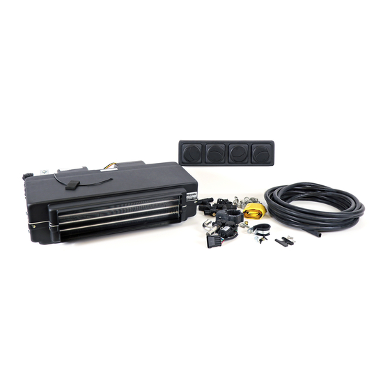
Page 6: Kit Contents For Kit 5012987
London 2. Kit Contents for kit 5012987 Item Part Number Description Number 5011500A HVAC KIT LONDON 12V W-THERMOSTAT 5011938A EDGE TRIM 0.125 X 0.5 INCH - 2FT 620406Z CABLE TIE 11 INCH BLACK 5011487A SCREW SELF-DIRLLING 0.25 X 1 INCH... - Page 7 ProMaster London Item Part Number Description Number 35814A WASHER M6X18X1.6 ZP OR CLEAR DIN9021 5011202A FITTING REFRIGERANT 45 -06MTHD -06HOSE 5011028A FITTING REFRIGERANT 45 -06THD -06HOSE 5011026A FITTING 45 REFRIGERANT -12CONN -10HOSE 5011023A FITTING REFRIGERANT 45 -6CONN -6HOSE 152560Z FEDERRING DIN128-A6-PHRF...
- Page 8 ProMaster London Item Part Number Description Number 901073Z HOSE - HEATER 5/8 INCH ID RUBBER 9.5 MT 5012120A BLEEDER VALVE 16mm OD 5012117A TEE COOLANT 16-20 PLASTIC BLACK KALORI 9027035A BAG BRACKET U4847econ FOR TP50E 1317523A CIRCULATION PUMP U4840 12V STD...
- Page 9 INSULATION HOSE ID 0.875IN X 6FT LONG 5001085A CABLE TIE HEAVY DUTY BLACK PPC301028A P-CLIP WITH RUBBER 60DIA X 12.7 5012587A HVAC HARNESS THERMOSTAT 5011932A PLUG FUSE ATM-APM MINI ADD-A-CIRCUIT 901406Z FUSE MINI 10 AMP RED 5011939A EDGE TRIM 0.250X0.5INCH-1FT 5011479A BRACKET MOUNTING SIDE-LONDON...
- Page 10 London Item Part Number Description Number 5011480A BRACKET MOTOR SUPPORT-LONDON 5011508A BRACKET SUPPORT LONDON PROMASTER 5011430A BRACKET PUMP PROMASTER 5011614A AC T BLOCK KIT PROMASTER 901100Z HOSE HEATER 0.75 ID GATES BLUE STRIPE 5013547A CONNECTING UNION - 17/20, PLASTIC KALORI...
- Page 11 ProMaster London Item Part Number Description Number 5012805A PROMASTER NEO CONTROL BRACKET 5012880A ADAPTER HARNESS NEO 2 5010321A COOLANT PUMP HARNESS 4500 5012877A BLOWER HARNESS NEO 4000-7000 5011861A SPRING CLAMP 22MM 5011862A SPRING CLAMP 27MM 5012430A HVAC HARNESS SOLENOID VALVE...
-
Page 12: Vehicle And Kit Preparation
London HVAC unit (1). NOTE: Avoid the blower housings when securing the bracket to the blower assembly. 2. Using two self-taping screws (8), install the rear support bracket (41) to the London unit in the area indicated in green. -
Page 13: Parts Required For Unit Installation
4. Parts Required for Unit Installation Item Part Number Description Number 5011938A EDGE TRIM 0.125X0.5INCH-2FT 5011508A BRACKET SUPPORT LONDON PROMASTER 5001321A BOLT HFH M6-1.0 6g x 20 8.8 ZP CLEAR 5011511A MOUNTING PLATE LONDON PROMASTER 5011487A SCREW SELF DIRLLING 0.25 X 1 INCH 620681053RA... - Page 14 ProMaster London 4. Drill a 3-inch hole (76 mm) 4 inches (102 mm) from the outside and front edges of the floor pan. Protect the edge against corrosion and install edge trim protection in both holes (2). 5. Trim 2” of foam from the left-side foam block as shown.
- Page 15 (42) using M6 bolts (7) and existing threaded holes. 8. Install the upper mounting plates (9) in the channel above the package tray. 9. Install the London HVAC unit in place using two M6 bolts (7) into the upper mounting plates.
- Page 16 ProMaster London 10. Bolt the overhead brace in place. 11. Using a ¼ inch X 1 inch-self- tapping bolt (4), attach the London lower bracket to the overhead brace.
- Page 17 ProMaster London NOTE: This measurement is not critical. 12. Measure 12 inches (305 millimeters) from the back wall of the package tray, and 9 inches (229 millimeters) from the left wall and drill a 1/4 inch (7 millimeters) hole in the center of the raised rib.
- Page 18 ProMaster London NOTE: Version 1 shown, version two will only have the black plastic sleeve. 14. Remove the following items from the refrigerant valve: • Yellow cap • Black threaded retainer • Black plastic sleeve (discard) NOTE: There is an arrow on the bottom of the valve to indicate the direction of flow.
- Page 19 ProMaster London 17. Install a short section of ¾ inch hose and a ¾ inch to 5/8 inch adapter on the output of the coolant pump (45, 46, 56). Install the pump and pump mount (25, 24) to the pump mounting bracket (43) using an M6 bolt and nut (7, 31).
-
Page 20: Parts Required For Wiring Installation
ProMaster London 5. Parts Required for Wiring Installation Item Part Number Description Number 5012813B CONTROLER NEO 2 HVAC 5012805A PROMASTER NEO CONTROL BRACKET 5011593A SCREW 4.2 X 16MM SELF DRILLING BLACK 5012880A ADDAPTER HARNESS NEO 2 5012877A BLOWER HARNESS NEO 4000-7000... - Page 21 ProMaster London 21. Remove the coin holder from the dashboard, below, and to the left of the steering wheel. 22. Cut the rear wall off of the coin holder to allow the wire harness to pass through. 23. Mount the controller (50, 51) in the coin holder using three self-tapping screws (32).
- Page 22 ProMaster London 24. Insert the blue wire labeled AC BLOWER ON from the NEO adapter harness (52) into cavity B of the blower harness X1 connector (54). 25. Connect the coolant pump (53), coolant valve (48), thermostat (36), and refrigerant valve harnesses (57) to the NEO adapter harness.
- Page 23 ProMaster London 27. Connect the two pink wires to the add-a-circuit (37). NOTE: Due to production differences, fuse panels may not be identical to this image. 28. Install the add-a-circuit to an ignition ON circuit position in the fuse panel (38).
- Page 24 ProMaster London 30. Route the wiring harnesses along the factory wiring runs and under the floor mat (if equipped). 31. Route the refrigerant valve and coolant valve harnesses up the b- pillar and onto the package shelf. NOTE: The refrigerant valve connector is not polarity sensitive.
- Page 25 ProMaster London 33. Reassemble the connector and insert the locking screw. 34. Install the o-ring and magnetic switch on the refrigerant valve. The magnet should snap in place. Connect the electrical connector. 35. Connect the blower motor and thermostat connectors.
- Page 26 38. Add foam insulation (33) to the exposed low-pressure hose in the upper package tray area. 39. Using the diffuser (27) as a template, mark and pre-drill the front of the London unit and attach the diffuser using two 4.2 X 16mm self-tapping screws (32).
-
Page 27: Parts Required For Hose Installation
ProMaster London 6. Parts Required for Hose Installation Item Part Number Description Number 5011023A FITTING REFRIGERANT 45 -6CONN -6HOSE 5011202A FITTING REFRIGERANT 45 -06MTHD -06HOSE 5011164A REFRIGERANT HOSE BURGAFLEX H-06-3090-R As Needed 152560Z FEDERRING DIN128-A6-PHRF 5011428A CAP SCREW SOCKET HD M6-1 12mm SS... - Page 28 ProMaster London...
- Page 29 40. Using the #6 fittings (15, 12) and hose (20), loosely install a refrigerant hose from the supply port on the London HVAC unit to the output port on the refrigerant valve (16, 17, 18). 41. Using the #10 fitting (14) and...
- Page 30 London to the coolant valve as shown. 44. Connect the 5/8” hose (21, 55) to the supply port on the London. Route the hose through the hole in the floor. Trim the coolant hose, leaving enough hose to reach the coolant pump installed earlier.
- Page 31 ProMaster London 46. Remove the nut and stud from the factory TXV. Set the A/C manifold aside. NOTE: Clean the mating surfaces on the TXV, H-Block, and A/C manifold. NOTE: Lubricate the supplied O- rings with PAG oil before installation.
- Page 32 ProMaster London NOTE: This is a parallel connection. Do not restrict or obstruct the coolant flow. 49. Install “T” fitting assembly in the heater core return hose as shown in the diagram (56). 50. Connect the coolant return hose from the coolant valve to the lower fitting on the “T”...
- Page 33 ProMaster London 52. Connect the 5/8” return hose to the inlet on the pump (56). Route the supply hose into the engine compartment. 53. Connect the ¾” coolant supply hose to the pump inlet (56). 54. Trim the fuel-filler shield shown.
- Page 34 Secure all hoses as necessary, keeping them away from hot and/or moving components (3, 57. Connect drain hoses (30) to the London HVAC unit. Route the left drain hose through the hole in the floor along with the other hoses.
- Page 35 ProMaster London 58. Remove the passenger’s side upper and lower A-pillar trim panels. 59. Route the right-side drain hose down the right A-pillar to the passenger’s foot-well. 60. Drill a 5/8 in. (16 mm) hole in two of the a-pillar trim stanchions as...
- Page 36 ProMaster London 61. Drill a 5/8 in. (16 mm) hole in the floor in the area indicated. Paint the cut edge to protect against corrosion. WARNING: Be sure to route the drain hose in a way that will not interfere with airbag deployment.
- Page 37 ProMaster London 64. Install the upper and lower A- pillar trim. 65. Cut both drain hoses approximately 1 1/2 in. (38 mm) below the body at a 45° angle away from the direction of travel.
-
Page 38: Initial Start
69. Turn the London blower on and request maximum heat. a. The coolant pump will turn on and coolant will begin to flow through the heat exchanger. 70. Using both the bleeder valve on the London unit and the vehicle’s coolant overflow cap, release trapped air from the system. -
Page 39: Wiring Diagram
ProMaster London 8. Wiring Diagram... - Page 40 Webasto Thermo & Comfort N.A., Inc. 15083 North Road Fenton, MI 48430 USA Phone: 810-593-6000 Fax: 810-593-6001 Internet: http://www.webasto.us http://www.techwebasto.com...
Need help?
Do you have a question about the London and is the answer not in the manual?
Questions and answers