
Related Manuals for Webasto London


Summary of Contents for Webasto London
- Page 1 2020 – Present Ram ProMaster London Installation Manual – Tie-In System ® 3.6 L Pentastar - All Wheelbases - High Roof Single Sliding Door Only For Kit number 5012739 Org. 01/2020 Rev. 05/2020 P/N: 5012416A...
-
Page 2: Table Of Contents
CONTENTS INTRODUCTION ..............................3 1.1. General Service and Safety Precautions ......................3 1.2. Refrigerants and Other Chemicals ........................ 3 1.3. System Flushing, Purging, and Pressure Testing for Leaks ................3 1.4. Scope ................................4 1.5. Applicability of Manual ..........................4 1.6. -
Page 3: Introduction
Failure to properly flush, purge, or pressure test a system for leaks can result in serious injury or death from explosion, fire or contact with acid-saturated refrigerant or oil mists. Webasto recommends that the system be serviced using a flush and purge station such as a Robinair ®... -
Page 4: Scope
CAUTION Location of the Webasto provided components, wiring and control devices are important for proper operation. Failure to comply with the installation instructions provided may result in poor operation or damage to the Webasto unit, the vehicle, or vehicle components. -
Page 5: Meaning Of Warnings, Cautions And Notes
608 of the Clean Air Act and that all refrigerant be reclaimed and recycled. Vehicle operation must not be impaired due to any Webasto installed components. All power circuits must be fused with an appropriate fuse or circuit breaker. -
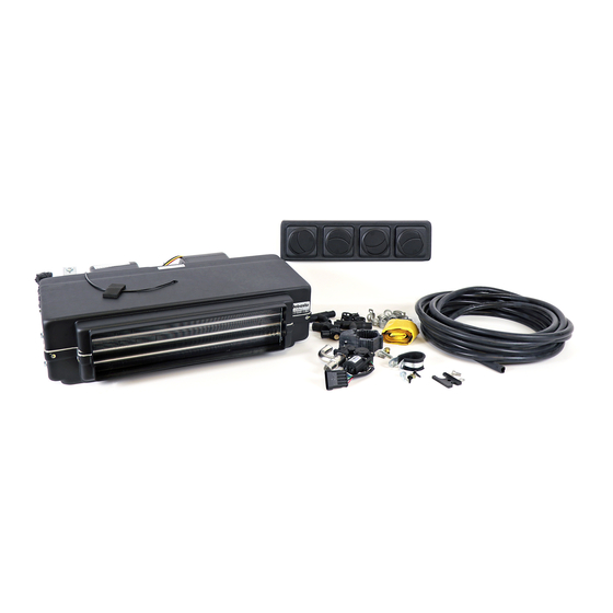
Page 6: Kit Contents For Kit 5012987
2. Kit Contents for kit 5012739 Item Part Number Description Number 62U003CF047EC HVAC KIT LONDON 12V 5013644A HARNESS – NEO 2 PROMASTER LONDON BRACKET – LONDON MOUNTING – 5012758A PROMASTER 5011556A INSULATION HOSE ID 0.875IN 0.5 Meters 62U003AA020B AIR DUCT OUTLET GRILL 5012416A MANUAL –... - Page 7 ProMaster London Item Part Number Description Number 5012418A - BAG PUMP U4847 HVAC 9017982A CIRCULATION PUMP – U4847 91318B SPRING CLAMP 17 MM 5012015A WASHER FLAT M6x18x1.6 5011567A WASHER LOCK SPLIT M6 5012791A BOLT – M6-1 x25 8.8 5012755A BRACKET – PUMP MOUNTING ALUMINUM...
- Page 8 BLEEDER VALVE 16mm OD 5011861A SPRING CLAMP 22MM 91318B SPRING CLAMP 17 MM 5013547A COUPLER – REDUCER 3/4 TO 5/8 6232398A WATER CONTROL VALVE 5012413A - BAG – INSTALLATION LONDON PROMASTER 5000531A RETAINER – ZIP TIE 5001085A CABLE TIE HEAVY DUTY BLACK...
- Page 9 BOLT HFH M6-1.0 6g x 20 8.8 ZP CLEAR 629069011A TEE – DRAIN HOSE 12MM OD 5011593A SCREW 4.2 X 16MM SELF DRILLING BLACK 5013005A - BAG – A/C PARTS LONDON PROMASTER 5011030B FITTING REFRIGERANT 45 -10THD TO -10H 5011028B FITTING REFRIGERANT 45 -06THD -06HOSE...
- Page 10 5013071A BAG – TXV PLATE 5013253A ANTI-CONDENSATION TAPE 1 METER 5013075A BAG – AC T-BLOCK PROMASTER 5013108A - BAG – CONTROL LONDON PROMASTER BRACKET – CONTROL HEAD NEO 2 5012805A PROMASTER 5013154A BAG – MINI FUSE AND PLUG 5011593A SCREW – 4.2 X 16MM...
-
Page 11: Vehicle And Kit Preparation
SCREW SELF-DIRLLING 0.25 X 1 INCH KIT PREPARATION NOTE: Some components in this document are pre-production. This does not affect function. 1. Remove the eight bolts from the side of the London unit and install the brackets (1, 3). Re-use the bolts that were removed. - Page 12 ProMaster London NOTE: The location is not critical. The hole should be approximately centered between the body plug and the fuel filler, and the inside and outside edges. 2. Drill a 3 inch (76 mm) hole behind the fuel filler cover.
- Page 13 5. Install the upper mounting plates (32) in the channel above the package tray. 6. Trim the package tray where needed and install the London HVAC unit in place using two M6 bolts, washers, and lock washers (13, 14, 15) into the upper...
- Page 14 ProMaster London 8. Install a short section of ¾ inch hose and a ¾ inch to 5/8 inch adapter on the output of the coolant pump (7, 11, 25, 23). Install the pump and pump mount to the pump mounting bracket using an M6 bolt and nut (16, 19).
- Page 15 ProMaster London 11. Attach the coolant valve to the tray in a location suitable for proper hose routing. (26, 27, 28, 31).
-
Page 16: Parts Required For Wiring Installation
ProMaster London 4. Parts Required for Wiring Installation Item Part Number Description Number 5013644A HARNESS – NEO 2 PROMASTER LONDON 5012805A BRACKET – CONTROL HEAD NEO 2 PROMASTER 5011593A SCREW – 4.2 X 16MM 5012814B CONTROLER NEO 2 HVAC 5013154A BAG –... - Page 17 ProMaster London 14. Cut the rear wall off the coin holder to allow the wire harness to pass through. 15. Connect the wiring harness (2) to the controller and mount the controller (44, 47) in the coin holder using three self-tapping screws (46).
- Page 18 ProMaster London NOTE: Do not install the fuse at this time. 17. Make the following electrical connections: • Battery + • Battery ground Position the relay and fuse holders in a location that allows servicing but protects them from damage.
- Page 19 ProMaster London 20. Connect the blower motor electrical connector. 21. Connect the coolant valve electrical connector. 22. Route the coolant pump wiring harness through the hole in the floor and connect the coolant pump.
-
Page 20: Parts Required For Hose Installation
ProMaster London 5. Parts Required for Hose Installation Item Part Number Description Number 5011030B FITTING REFRIGERANT 45 -10THD TO -10H 5011028B FITTING REFRIGERANT 45 -06THD -06HOSE 5011026B FITTING 45 REFRIGERANT -12CONN -10HOSE 5011023B FITTING REFRIGERANT 45 -6CONN -6HOSE 5012451A HOSE REFRIGERANT – SIZE -10... - Page 21 ProMaster London AC Hose Crimping The proper method for crimping A/C hoses is outlined below. Refer to these steps if you are unfamiliar with making A/C hoses. Using blade-type hose cutters, cut the hose in one cut. The cut edge must be clean and flush.
- Page 22 ProMaster London Lubricate the fitting with PAG oil and insert the fitting until the shoulder of the fitting is touching the clip holder. Using Oetiker pliers, crimp the clips closed. (Webasto P/N 5012954A)
- Page 23 ProMaster London...
- Page 24 London. Route the hose through the hole drilled in the floor. 24. Using the #10 fitting (38) and hose (9) install a refrigerant hose from the London HVAC unit low- pressure fitting through the hole in the floor. Install the TXV plate (41) 25.
- Page 25 26. Using a length of 5/8” heater hose and a bleeder valve (8, 22, 24) connect the return (top) port of the London to the coolant valve as shown. 27. Connect the heater hose from the inlet on the coolant valve (24).
- Page 26 ProMaster London NOTE: Clean the mating surfaces on the TXV, H-Block, and A/C manifold. NOTE: Lubricate the supplied O- rings with PAG oil before installation. 29. Using the supplied bolt, install the A/C manifold and the T-Block (43) to the TXV.
- Page 27 ProMaster London NOTE: This is a parallel connection. Do not restrict or obstruct the coolant flow. 32. Install “T” fitting assembly in the heater-core return hose as shown in the diagram (23). The 3/4” port should be above the 5/8” port.
- Page 28 ProMaster London 35. Connect the 5/8” return hose to the reducer installed on the outlet of the coolant pump installed earlier (12). 36. Connect the ¾” coolant supply hose to the pump inlet. NOTE: This step is optional. 37. Trim the fuel-filler shield shown.
- Page 29 ProMaster London 38. Connect drain hose to the London HVAC unit. Using the T fitting (34) connect them together and route the drain hose down the left b- pillar and through the hole in the floor. 39. Trim the drain hose about 2”...
-
Page 30: Initial Start
The coolant pump will turn on and coolant will begin to flow through the heat exchanger. 46. When pressure bleeding, Use both the bleeder valve on the London unit and the vehicle’s coolant overflow cap, release trapped air from the system. -
Page 31: Wiring Diagram
ProMaster London 7. Wiring Diagram... - Page 32 Webasto Thermo & Comfort N.A., Inc. 15083 North Road Fenton, MI 48430 USA Phone: 810-593-6000 Fax: 810-593-6001 Internet: http://www.webasto.us http://www.techwebasto.com...
Need help?
Do you have a question about the London and is the answer not in the manual?
Questions and answers