Table of Contents
Advertisement
Advertisement
Table of Contents

Related Manuals for Veolia Hydrotech Drumfilter HDF - 16/20V- Value Series


Summary of Contents for Veolia Hydrotech Drumfilter HDF - 16/20V- Value Series
- Page 1 Drumfilter HDF - 16/20V- Value Series Operation and maintenance manual...
-
Page 2: Table Of Contents
Table of contents 1. INTRODUCTION 2. SAFETY INSTRUCTIONS 2.1 Warning symbols 2.2 CE marking 2.3 Conversion 2.4 Personnel requirements 2.5 Emergency stop 2.6 Electrical safety 2.7 Safety instructions 3. DRUMFILTER 16V & 20V -VALUE SERIES 3.1 Overview 3.2 Identifying the filter 4. - Page 3 5.5 Checking drum rotation 5.6 Pipe connections 5.7 Backwash system 5.8 Filter placement 6. START-UP AND OPERATION 6.1 Check procedures during start-up 6.2 Automatic settings 6.2.1 Cleaning with integrated HPC (optional) 6.2.2 Level differences 6.2.3 Operating mode HAND – continuous rotation/washing 6.2.4 Operating mode AUTO –...
- Page 4 8.2 Wash water filter 8.3 Bearings 8.3.1 Lubrication 8.3.2 Checking centre bearings for wear 8.4 Filter element 8.4.1 High pressure cleaning 8.4.2 Chemical cleaning of filter elements 8.4.3 Replacing filter elements 8.4.4 ALPHAFLEX™ 8.5 Drive chain 8.5.1 Checking and tensioning the drive chain 8.5.2 Using the chain tensioner to achieve correct tension 8.5.3 Replacing the drive chain 8.6 Rubber seal...
-
Page 5: Introduction
1. INTRODUCTION This manual contains instructions for operation and maintenance of Hydrotech Drum Filter Value series, HDF16V & 20V. Pay attention to all warning symbols that appear in this manual. If this in- formation is ignored it may result in serious personal injury and/or damage to equipment. The manual must always be available to personnel working with the equipment. -
Page 6: Safety Instructions
2. SAFETY INSTRUCTIONS Hydrotech Drum Filter Value series HDF16 & 20V, is designed for safe operation provided that it is installed correctly and used in accordance with the enclosed instructions. The equipment must be installed correctly and adapted in accordance with local regulations. This equipment is desig- ned for use by one or more operators. -
Page 7: Personnel Requirements
that are used in conversion/reconstruction of the equipment. The warning symbols and CE mar- king must be attached where they are fully visible. If any part of the equipment with a warning symbol is replaced, a new symbol must be attached in the same position. Damaged symbols and CE markings must be replaced immediately. - Page 8 Access to the filter by unauthorised persons is strictly prohibited. Outdoor installations must be fenced in. The drum can begin rotating without warning if automatic control is activated. Moving parts must not be touched. Safety guards are fitted around the power transmission and in front of the support wheels. Always make sure these are secured and correctly fitted.
-
Page 9: Drumfilter 16V & 20V -Value Series
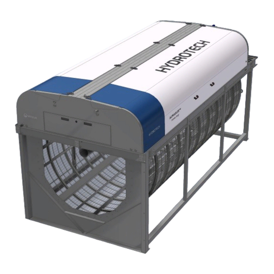
3. DRUMFILTER 16V & 20V -VALUE SERIES 3.1 Overview Figure 3.1 HDF 16V & 20V Frame version, side view. Operation & maintenance manual, Drum filter HDF 16/20V - Value series... - Page 10 Figure 3.1 HDF 16V & 20V Frame version, front view. Operation & maintenance manual, Drum filter HDF 16/20V - Value series...
- Page 11 Figure 3.1 HDF 16V & 20V Frame version, rear view. Operation & maintenance manual, Drum filter HDF 16/20V - Value series...
-
Page 12: Identifying The Filter
3.2 Identifying the filter The filter type, serial number and year of manufacture are stated on the identification plate. The filter type and serial number are also stated on the front of this manual. Figure 3.3 Filter identification plate. Figure 3.4 Definition of filter type. Operation &... -
Page 13: Reception And Handling
4. RECEPTION AND HANDLING 4.1 Reception Once the equipment has been delivered and received it must be thoroughly checked for trans- port damage. Document any transport damage before further handling of the equipment. The consignment note, manual and spare part kit are attached to the equipment. Check all parts against the consignment note. -
Page 14: General Installation Instructions
5. GENERAL INSTALLATION INSTRUCTIONS The following requirements must be fulfilled before installation can begin: ⊲ The electrical specifications for the equipment must be in agreement with the applicable spe- cifications for the available power grid. ⊲ The equipment is free from damage (no damage incurred during transport or storage). 5.1 Installation site 5.1.1 Outdoor installation For outdoor installation it is important to pro-... -
Page 15: Electrical Connection
5.3 Electrical connection Electrical connection must be done in accordance with local regulations. Check that the settings on the motor protection device correspond with the motor data (see Appendices A and D). 5.4 Equipotential bonding The Hydrotech Drum Filter and associated equipment should be protected with a suitable sys- tem for potential equalisation. -
Page 16: Start-Up And Operation
6. START-UP AND OPERATION 6.1 Check procedures during start-up 1. Check that the drive unit cover is installed correctly. 2. Turn the pump switch to the OFF (0) position (see F in Figure 6.1). 3. Set the main power switch to the ON (1) position (see J in Figure 6.1). 4. -
Page 17: Automatic Settings
6.2 Automatic settings The control system for HDF16V & 20V, must always be equipped with a frequency converter. This is factory calibrated if delivered from Hydrotech. To perform a soft start of the drive motor, the frequency converter settings must be min. 5 sec “ramp up” and min. 3 sec ”ramp down”. The filter works with 50 Hz as standard. -
Page 18: Cleaning With Integrated Hpc (Optional)
Figure 6.2 Hydrotech standard control cabinet, type PFC (option). (The control cabinet’s construction is in general adapted to the respective application). A. Motor protection pump B. Fuses C. Logic module D. Contactor, pump E. Control relays F. Level relays G. Frequency converter H. -
Page 19: Level Differences
2. Start the HPC programme with HPC START (see figure 6.2.1). Indicator light HPC OPERATION indicates that the HPC programme is running. 3. When the cleaning programme has ended, the filter returns to normal operation in AUTO mode. During the cleaning cycle, the machine continues to continuously filter with the pump in auto- matic mode. -
Page 20: Operating Mode Hand - Continuous Rotation/Washing
6.2.3 Operating mode HAND – continuous rotation/washing Operation with continuous drum rotation and backwash. In this mode, the water level inside the drum is kept virtually constant. The level sensor and the automatic control system are disabled when the HAND operating mode is selected. 6.2.4 Operating mode AUTO –... -
Page 21: Adjusting Delay Time
6.2.6 Adjusting delay time A time relay/logic module is used to delay the backwash stop after the water level has dropped below the level sensor. The time relay/logic module is pre-set so that the drum is backwashed for one revolution after the water level has dropped below the level sensor. In certain applications it can be necessary to increase the time that the filter is backwashed after the water level has dropped below the level sensor to prevent future clogging. -
Page 22: Function
7. FUNCTION 7.1 Intended use The filter is designed and manufactured to remove solid particles in unpressurised water flow systems. The filter is not a pressure vessel. 7.2 Non-intended use Unless approved in writing by Hydrotech, the filter must not be used to filter liquids other than water. -
Page 23: Maintenance/Service
8. MAINTENANCE/SERVICE 8.1 Backwash system The most common cause of disruption in the wash water system is nozzle clogging. Clogging is caused by particles in the wash water and/or by e.g. biological fouling in the pipe system. The correct dispersal pattern is shown below for wash water. Clogged nozzles can produce a dif- ferent dispersal pattern. - Page 24 4. Remove the nozzle nut of a clogged nozzle by turning it a ¼ turn anticlockwise. Exercise care so as not to lose the rubber seal. 5. Clean the tip of the nozzle with compressed air or with a plastic brush. Never use a steel brush or metal pins as these may damage the nozzle.
-
Page 25: Nozzle Overview
8.1.2 Nozzle overview Figure 8.3.1 below shows nozzle types that may be used with the HDFV series filter. Figure 8.3.1 Nozzle components A. Top nozzle attachment B. Rubber seal C. Top: Nozzle nut, self cleaning (optional) Bottom: Standard nozzle D. Bottom nozzle attachment E. -
Page 26: Wash Water Filter
8.2 Wash water filter A wash water filter should be used to remove particles from the backwash water. Figure 8.4 Wash water filter (option) If the pressure gauge indicates a pressure that is more than 0.5 bar below normal pressure, it is time to clean the wash water filter. -
Page 27: Bearings
8.3 Bearings 8.3.1 Lubrication HDF 16V & 20V -series filter: The drum’s centre shaft and support wheels contains bearings that must be lubricated. The filter is equipped with automatic greasers as standard. NB. Prior to service, read section 2.7 (Safety instructions). 8.3.2 Checking centre bearings for wear The centre shaft bearings must be checked for wear in accordance with the maintenance chart. -
Page 28: Filter Element
8.4 Filter element 8.4.1 High pressure cleaning It may sometimes be necessary to manually clean the filter elements. An indication that manual cleaning is required is increased frequency of automatic backwashing. Manual cleaning can be done using a high pressure washer. NB. - Page 29 If necessary clean the chemical ramp’s nozzles as set out below: 1. Remove the nozzle by turning it a 1/4 turn anticlockwise (see Figure 8.6). 2. Clean the nozzle with compressed air or a plastic brush. Never use a wire brush, metal pins or similar as these can damage the nozzle.
-
Page 30: Replacing Filter Elements
8.4.3 Replacing filter elements 1. Turn the main power switch to the OFF (0) position and lock it in the OFF (0) position with a padlock. 2. Unscrew the nuts that secure the tensioning straps at the drum (see Figure 8.7.a). 3. -
Page 31: Alphaflex
8.4.4 ALPHAFLEX™ Hydrotechs ALPHAFLEX™ panels are designed to be mounted in one of two ways. The panel will either work to scoop and carry water (+ sign in the direction of rotation) each time it breaks the water surface inside the drum, or if it is mounted the other way around (- sign in the direction of rotation), it will rotate passively. -
Page 32: Drive Chain
8.5 Drive chain NB Prior to servicing, read section 2.7. The filter is equipped with a chain drive. For technical data, see Appendices A and D. 8.5.1 Checking and tensioning the drive chain 1. Turn the main power switch to the OFF (0) position and lock with a padlock. 2. -
Page 33: Using The Chain Tensioner To Achieve Correct Tension
8.5.2 Using the chain tensioner to achieve correct tension 1. Turn the main power switch to the OFF (0) position and lock with a padlock. 2. Remove the motor cover to access the chain. Figure 8.10 The screws holding the flooring tile highlighted in blue. (figure above is from a discfilter unit, the principle is the same for drumfilters) 3. - Page 34 Figure 8.11 Detailed view of the chain tensioner. (figure above is from discfilter, the principle is the same for drumfilters) 4. Loosen the two screws to the left in figure 8.11. The screws are loosend enough when the chain tensioner is able to move freely. Be careful when loosening the screws to ensure that the bracket underneath the beam don’t fall off.
-
Page 35: Replacing The Drive Chain
8.5.3 Replacing the drive chain 1. Turn the main power switch to the OFF position and lock with a padlock. 2. Get maximum amount of slack on the drive chain by using the chain tensioner. For further information of how to use the chain tensioner, read section 8.5.2. 3. -
Page 36: Lifting The Drum
8.8 Lifting the drum 8.8.1 Rear side The filter is equipped with four lifting lugs, placed at the rear of the drum. Two lugs are placed at the drum and two lugs is placed at the inside of the frame, see figure 8.14 below. Figure 8.14 The lifting lugs at the drum and inside of the fram shown in blue. -
Page 37: Front Side
8.8.1 Front side At the front side of the filter place a lifting jack along the centerline of the filter. Gently lift the drum, see figure 8.16 below. Figure 8.16 Lifting the front side of the drum with a lifting jack. Operation &... -
Page 38: Maintenance Chart
8.9 Maintenance chart The maintenance interval shown in the table below is the maximum allowed time interval during typical service conditions. Note! Your specific service conditions may differ from what Hydrotech considers to be typical conditions. In these cases the time between maintenance needs to be adjusted meet your spe- cific requirements. - Page 39 Changing gear box oil. Follow the gear box manufactorers See Appendix F. recommendation. Hydrotechs recommendation is to do this using a suction hose due to space restrictions. NB. Prior to service, read section 2.7 (Safety instructions). Clean the strainer at the bottom of the MTR pump (optio- Every week or at another interval based on nal equipment) using a brush.
-
Page 40: Troubleshooting
9. TROUBLESHOOTING Problem Possible cause Solution 1. The filter does not start A. The water has low conductivity. A. Increase the sensitivity by tur- despite the water level in ning the selector for the level re- the drum having reached lay towards MAX. -
Page 41: Symbols Used On Hydrotech Filters
Symbols used on Hydrotech filters Symbol is displaying equipotential earth bonding points on the filter. Symbol shown at lubrication points on the filter. Read the manual for fur- ther information about lubrication. Symbol displaying moving parts. Neg- ligence to comply with safety regula- tions may lead to injury. -
Page 42: Manuals & Technical Information
Manuals & technical information For further information regarding Hydrotech filters or any other product used together with Hydrotech filters, please visit www.hydrotech.se. Click on ”Manuals & technical information”. Locate the desired product manual and select manual by clicking on one of the language options. - Page 43 Hydrotech AB A Veolia Solutions & Technologies Company Mejselgatan 6 235 32 Vellinge Sweden Telephone: +46 (0)40 - 42 95 30 Fax: +46 (0)40 - 42 95 31 E-mail: mailbox@hydrotech.se Webpage: www.hydrotech.se Copyright © All rights reserved...
Need help?
Do you have a question about the Hydrotech Drumfilter HDF - 16/20V- Value Series and is the answer not in the manual?
Questions and answers